Achieving Invisibility of Homogeneous Radially Anisotropic Cylinders by Effective Medium Theory

Y.X. Ni1, L. Gao1111E-mail: leigao@suda.edu.cn, and C.W. Qiu2222E-mail: cwq@mit.edu 1 Jiangsu Key Laboratory of Thin Films, Department of Physics, Soochow University, Suzhou 215006, China
2 Research Laboratory of Electronics, Massachusetts Institute of Technology, 77 Massachusetts Avenue, Cambridge MA 02139, US
Abstract

In this paper, we establish the full-wave electromagnetic scattering theory to study the electromagnetic scattering from infinitely long cylinders with radially anisotropic coatings. We show that the total effective scattering width can be dramatically reduced by the suitable adjustment of the dielectric anisotropy of the shell, while it is not the case for tuning the dielectric anisotropy of the core. Furthermore, we could make the cylindrical objects invisible when both dielectric and magnetic anisotropies are adjusted. In the long wavelength limit, we develop effective medium theory to derive the effective isotropic permittivity and permeability for the anisotropic coated cylinders, and the invisibility radius ratio derived from the full-wave theory for small coated cylinders can be well described within the effective medium theory.

Index Terms: Electromagnetic scattering, radial anisotropy, effective medium theory, coated cylinder, invisibility

I Introduction

In recent years, designing optical and electromagnetic (EM) invisibility cloaking devices has attracted great attention from both physics and engineering societies. Scientists have developed coordinate transformation method Pendry and conformal mapping method Leonhardt , which can protect the cloaked object of arbitrary shape from electromagnetic radiation. This idea has been verified by full-wave simulation of the cylindrical cloaking structure based on both finite element method (FEM) Cummer and finite-difference time-domain method (FDTD) Zhao . The experimental demonstration at microwave frequencies Schurig and even at optical frequencies Cai1 for non-magnetic material has been realized lately. They have investigated the transformation based cloaks possessing spherical/cylindrical geometries with rotational symmetry Pendry ; Schurig ; Ruan ; Chen1 ; Jiang and geometries with reduced symmetries, such as eccentric elliptic cylinders Kwon , square cloaks Rahm , and arbitrary shapes numerical1 . In addition to the method of spatial transformation, Alu et. al. have proposed to use isotropic plasmonic coatings to render objects invisible Alu2 based on the dipolar cancellation, and proposed a parallel-plate metamaterial cloak Silveirinha that significantly reduces the total scattering cross section of a given two-dimensional dielectric obstacle in some frequency band.

Due to the spatial compression, the required parameters should be anisotropic and dependent on the position Pendry . To alleviate these contraints, EM invisibility cloaks have been realized by isotropic coatings based on the effective medium theory Gao ; Qiu_PRE2009 . However, it still requires sufficient layers of alternating isotropic media in order to maintain the validity of that effective medium theory. Although recent development in metamaterial may allow the control of material parameters, such strict requirements for the parameters of a perfect cloak are still too difficult to realize in practice. As a way to reduce the number of required constitutive parameters to realize a manufacturable cloak, the incidence can be decomposed into transverse electric (TE) and transverse magnetic (TM) components so that 2D cloaks with simplified parameters Yan1 ; Luo can be used. Unfortunately, the simplified cylindrical cloak will cause large reflection at the cloak’s outer boundary due to the impedance mismatch. From the discussion above, one can see that: (1) ideal cylindrical cloaks require 6 parameters, some of which are infinite values; (2) simplified cylindrical cloaks requires 3 parameters but still some value tends to the infinity at the inner boundary; (3) both ideal and simplified cylindrical cloaks need certain parameters to be inhomogeneous i.e., a function of position. This motivates our current work on achieving cylindrical cloaks, which is based on only one single coating by a homogeneous and radially anisotropic medium. The invisibility condition can be established by the effective medium theory. It is obvious that the contraints in material fabrication are greatly alleviated.

A lot of theoretical and numerical approaches have been developed to deal with the scattering problem of homogeneous anisotropic or even gyrotropic cylinders, e.g., integrodifferential equation Uslenghi ; Uslenghi_2 , volumetric integral equation method ZNChen_1 , combined field surface integral equation method ZNChen_2 , finite difference method with measured equation of invariance (FD-MEI) ZNChen_1 , and dyadic Green’s functions cttai:1994 ; nkuzunoglu:1995 ; Qiu_PRB_2006 . However, it should be noted that all these anisotropic tensors in those mentioned papers are defined in Cartesian coordinates, which is different from the radially anisotropy defined in the cylindrical coordinates as discussed in this paper. Although the latter can be mapped into Cartesian anisotropy, then the anisotropic cylinder will be inhomogeneous and angle-dependent.

Following our discussed motivation, in order to investigate the EM invisibility of radially anisotropic coated cylinders, we develop the compact scattering theorem for a coated cylinder with homogeneous radial anisotropy, by extending the idea of embedding radial anisotropy in the orders of Bessel/Hankel functions in spherical case Qiu_TAP_2007 . We focus our analysis on the invisibility characteristics of a homogeneous anisotropic coated cylinder. EM field components and scattering width of such coated cylinders are formulated. We discuss the roles of anisotropic parameters as well as the core-shell ratio on the reduction of the total scattering section. From the scattering algorithm, the effective permeability and permittivity of the core-shell system are also established so that the required condition for invisibility performance can be exactly determined. The numerical results are given.

II Full-wave electromagnetic scattering theory

Let us consider the electromagnetic scattering from a radially-anisotropic coated cylinder of infinite length (see Fig. 1).

Refer to caption
Figure 1: Geometry of the scattering of a plane wave by a coated cylinder with permittivity and permeability of radially anisotropic tensors. The incident wave propagates along x-axis, and the magnetic field is along z-axis.

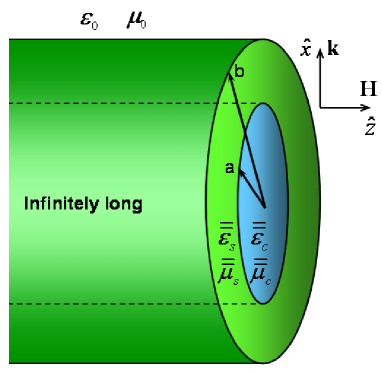
For the simplicity, we assume a normally incident plane wave with the magnetic field along the z direction (i.e., the transverse magnetic (TM) wave). We assume that the coated cylinder is composed of the core with the radius a𝑎a and the shell with the radius b𝑏b, and it is surrounded by free space (ε0,μ0)subscript𝜀0subscript𝜇0(\varepsilon_{0},\mu_{0}). As for radial anisotropy, we indicate that the permeability and the permittivity tensors for the core and the shell can be expressed in cylindrical coordinates (r^,θ^,z^)^𝑟^𝜃^𝑧(\hat{r},\hat{\theta},\hat{z}),

ε¯¯psubscript¯¯𝜀𝑝\displaystyle\overline{\overline{\varepsilon}}_{p}\mbox{$$} =\displaystyle= (εpr000εpθ000εpz)subscript𝜀𝑝𝑟00missing-subexpressionmissing-subexpressionmissing-subexpressionmissing-subexpressionmissing-subexpressionmissing-subexpressionmissing-subexpressionmissing-subexpressionmissing-subexpressionmissing-subexpressionmissing-subexpressionmissing-subexpressionmissing-subexpressionmissing-subexpressionmissing-subexpressionmissing-subexpressionmissing-subexpression0subscript𝜀𝑝𝜃0missing-subexpressionmissing-subexpressionmissing-subexpressionmissing-subexpressionmissing-subexpressionmissing-subexpressionmissing-subexpressionmissing-subexpressionmissing-subexpressionmissing-subexpressionmissing-subexpressionmissing-subexpressionmissing-subexpressionmissing-subexpressionmissing-subexpressionmissing-subexpressionmissing-subexpression00subscript𝜀𝑝𝑧missing-subexpressionmissing-subexpressionmissing-subexpressionmissing-subexpressionmissing-subexpressionmissing-subexpressionmissing-subexpressionmissing-subexpressionmissing-subexpressionmissing-subexpressionmissing-subexpressionmissing-subexpressionmissing-subexpressionmissing-subexpressionmissing-subexpressionmissing-subexpressionmissing-subexpression\displaystyle\mbox{$$}\left({\begin{array}[]{*{20}c}{\varepsilon_{pr}}&0&0\\ 0&{\varepsilon_{p\theta}}&0\\ 0&0&{\varepsilon_{pz}}\\ \end{array}}\right) (1d)
μ¯¯psubscript¯¯𝜇𝑝\displaystyle\overline{\overline{\mu}}_{p}\mbox{$$} =\displaystyle= (μpr000μpθ000μpz),subscript𝜇𝑝𝑟00missing-subexpressionmissing-subexpressionmissing-subexpressionmissing-subexpressionmissing-subexpressionmissing-subexpressionmissing-subexpressionmissing-subexpressionmissing-subexpressionmissing-subexpressionmissing-subexpressionmissing-subexpressionmissing-subexpressionmissing-subexpressionmissing-subexpressionmissing-subexpressionmissing-subexpression0subscript𝜇𝑝𝜃0missing-subexpressionmissing-subexpressionmissing-subexpressionmissing-subexpressionmissing-subexpressionmissing-subexpressionmissing-subexpressionmissing-subexpressionmissing-subexpressionmissing-subexpressionmissing-subexpressionmissing-subexpressionmissing-subexpressionmissing-subexpressionmissing-subexpressionmissing-subexpressionmissing-subexpression00subscript𝜇𝑝𝑧missing-subexpressionmissing-subexpressionmissing-subexpressionmissing-subexpressionmissing-subexpressionmissing-subexpressionmissing-subexpressionmissing-subexpressionmissing-subexpressionmissing-subexpressionmissing-subexpressionmissing-subexpressionmissing-subexpressionmissing-subexpressionmissing-subexpressionmissing-subexpressionmissing-subexpression\displaystyle\mbox{$$}\left({\begin{array}[]{*{20}c}{\mu_{pr}}&0&0\\ 0&{\mu_{p\theta}}&0\\ 0&0&{\mu_{pz}}\\ \end{array}}\right), (1h)

where ε¯¯psubscript¯¯𝜀𝑝\overline{\overline{\varepsilon}}_{p} (or μ¯¯psubscript¯¯𝜇𝑝\overline{\overline{\mu}}_{p}) represents the permittivity (or permeability) tensor of the core by p=c𝑝𝑐p=c and/or the shell by p=s𝑝𝑠p=s.

In Fig. 1, the incident magnetic field with unit amplitude can be written as Hz=eik0xiωtsubscript𝐻𝑧superscript𝑒𝑖subscript𝑘0𝑥𝑖𝜔𝑡H_{z}=e^{ik_{0}x-i\omega t}, where k0=ωε0μ0subscript𝑘0𝜔subscript𝜀0subscript𝜇0k_{0}=\omega\sqrt{\varepsilon_{0}\mu_{0}}. In what follows, eiωtsuperscript𝑒𝑖𝜔𝑡e^{-i\omega t} will be omitted. In this connection, Maxwell equations in the core and shell are written as,

×𝐇𝐇\displaystyle\nabla\times{\bf{H}}\mbox{$$} =\displaystyle= iωε¯¯𝐄𝑖𝜔¯¯𝜀𝐄\displaystyle\mbox{$$}-i\omega\overline{\overline{\varepsilon}}\cdot{\bf{E}} (2a)
×𝐄𝐄\displaystyle\nabla\times{\bf{E}}\mbox{$$} =\displaystyle= iωμ¯¯𝐇.𝑖𝜔¯¯𝜇𝐇\displaystyle\mbox{$$}i\omega\overline{\overline{\mu}}\cdot{\bf{H}}. (2b)

In cylindrical coordinates, Eq. (2) can be decomposed into

iωμprHr𝑖𝜔subscript𝜇𝑝𝑟subscript𝐻𝑟\displaystyle i\omega\mu_{pr}H_{r}\mbox{$$} =\displaystyle= 1rEzθEθz1𝑟subscript𝐸𝑧𝜃subscript𝐸𝜃𝑧\displaystyle\mbox{$$}\frac{1}{r}\frac{{\partial E_{z}}}{{\partial\theta}}-\frac{{\partial E_{\theta}}}{{\partial z}} (3a)
iωμpθHθ𝑖𝜔subscript𝜇𝑝𝜃subscript𝐻𝜃\displaystyle i\omega\mu_{p\theta}H_{\theta}\mbox{$$} =\displaystyle= ErzEzrsubscript𝐸𝑟𝑧subscript𝐸𝑧𝑟\displaystyle\mbox{$$}\frac{{\partial E_{r}}}{{\partial z}}-\frac{{\partial E_{z}}}{{\partial r}} (3b)
iωμpzHz𝑖𝜔subscript𝜇𝑝𝑧subscript𝐻𝑧\displaystyle i\omega\mu_{pz}H_{z}\mbox{$$} =\displaystyle= 1r(rEθ)r1rErθ1𝑟𝑟subscript𝐸𝜃𝑟1𝑟subscript𝐸𝑟𝜃\displaystyle\mbox{$$}\frac{1}{r}\frac{{\partial(rE_{\theta})}}{{\partial r}}-\frac{1}{r}\frac{{\partial E_{r}}}{{\partial\theta}} (3c)
iωεpzEz𝑖𝜔subscript𝜀𝑝𝑧subscript𝐸𝑧\displaystyle-i\omega\varepsilon_{pz}E_{z}\mbox{$$} =\displaystyle= 1r(rHθ)r1rHrθ1𝑟𝑟subscript𝐻𝜃𝑟1𝑟subscript𝐻𝑟𝜃\displaystyle\mbox{$$}\frac{1}{r}\frac{{\partial(rH_{\theta})}}{{\partial r}}-\frac{1}{r}\frac{{\partial H_{r}}}{{\partial\theta}} (3d)
iωεprEr𝑖𝜔subscript𝜀𝑝𝑟subscript𝐸𝑟\displaystyle-i\omega\varepsilon_{pr}E_{r}\mbox{$$} =\displaystyle= 1rHzθHθz1𝑟subscript𝐻𝑧𝜃subscript𝐻𝜃𝑧\displaystyle\mbox{$$}\frac{1}{r}\frac{{\partial H_{z}}}{{\partial\theta}}-\frac{{\partial H_{\theta}}}{{\partial z}} (3e)
iωεpθEθ𝑖𝜔subscript𝜀𝑝𝜃subscript𝐸𝜃\displaystyle-i\omega\varepsilon_{p\theta}E_{\theta}\mbox{$$} =\displaystyle= HrzHzr.subscript𝐻𝑟𝑧subscript𝐻𝑧𝑟\displaystyle\mbox{$$}\frac{{\partial H_{r}}}{{\partial z}}-\frac{{\partial H_{z}}}{{\partial r}}. (3f)

After some algebraic manipulations, we can obtain the governing equation of Hzsubscript𝐻𝑧H_{z}

1εpθr(rHzr)+1rεpr2Hzθ2+ω2μpzrHz=0.1subscript𝜀𝑝𝜃𝑟𝑟subscript𝐻𝑧𝑟1𝑟subscript𝜀𝑝𝑟superscript2subscript𝐻𝑧superscript𝜃2superscript𝜔2subscript𝜇𝑝𝑧𝑟subscript𝐻𝑧0\displaystyle\frac{1}{{\varepsilon_{p\theta}}}\frac{\partial}{{\partial r}}(r\frac{{\partial H_{z}}}{{\partial r}})+\frac{1}{{r\varepsilon_{pr}}}\frac{{\partial^{2}H_{z}}}{{\partial\theta^{2}}}+\omega^{2}\mu_{pz}rH_{z}=0. (4)

Inserting the solution in the form of Hz=Ψ(r)Θ(θ)subscript𝐻𝑧Ψ𝑟Θ𝜃H_{z}=\Psi(r)\Theta(\theta) and introducing a seperation term m2superscript𝑚2m^{2}, one obtains the ordinary differential equation for Ψ(r)Ψ𝑟\Psi(r)

r2d2Ψ(r)dr2+rdΨ(r)dr+(ω2εpθμpzr2m2εpr/εpθ)Ψ(r)=0.superscript𝑟2superscript𝑑2Ψ𝑟𝑑superscript𝑟2𝑟𝑑Ψ𝑟𝑑𝑟superscript𝜔2subscript𝜀𝑝𝜃subscript𝜇𝑝𝑧superscript𝑟2superscript𝑚2subscript𝜀𝑝𝑟subscript𝜀𝑝𝜃Ψ𝑟0\displaystyle r^{2}\frac{{d^{2}\Psi(r)}}{{dr^{2}}}+r\frac{{d\Psi(r)}}{{dr}}+\left(\omega^{2}\varepsilon_{p\theta}\mu_{pz}r^{2}-\frac{{m^{2}}}{{\varepsilon_{pr}/\varepsilon_{{}_{p\theta}}}}\right)\Psi(r)=0. (5)

For the part Θ(θ)Θ𝜃\Theta(\theta), we have the form eimθsuperscript𝑒𝑖𝑚𝜃e^{im\theta}. The general solution to Eq. (5) is AJpm(kpr)+BNpm(kpr)𝐴subscript𝐽𝑝𝑚subscript𝑘𝑝𝑟𝐵subscript𝑁𝑝𝑚subscript𝑘𝑝𝑟AJ_{pm}(k_{p}r)+BN_{pm}(k_{p}r), where Jpmsubscript𝐽𝑝𝑚J_{pm} and Npmsubscript𝑁𝑝𝑚N_{pm} respectively denote the m𝑚{m}th-order Bessel and Neumann functions with the argument of kprsubscript𝑘𝑝𝑟k_{p}r, kp2=ω2εpθμpzsuperscriptsubscript𝑘𝑝2superscript𝜔2subscript𝜀𝑝𝜃subscript𝜇𝑝𝑧k_{p}^{2}=\omega^{2}\varepsilon_{p\theta}\mu_{pz}, and (pm)2=m2(εpr/εpθ)superscript𝑝𝑚2superscript𝑚2subscript𝜀𝑝𝑟subscript𝜀𝑝𝜃(pm)^{2}=\frac{{m^{2}}}{{(\varepsilon_{pr}/\varepsilon_{p\theta})}}. Note that if it is an isotropic case (i.e., εpr=εpθsubscript𝜀𝑝𝑟subscript𝜀𝑝𝜃\varepsilon_{pr}=\varepsilon_{p\theta}), pm𝑝𝑚pm reduces to be an integer.

In order to match the boundary conditions at cylindrical interfaces, the incident magnetic field can be expanded as follows,

Hzinc=eik0x=eik0rcosθ=m=+imJm(k0r)eimθ.subscriptsuperscript𝐻𝑖𝑛𝑐𝑧superscript𝑒𝑖subscript𝑘0𝑥superscript𝑒𝑖subscript𝑘0𝑟𝜃superscriptsubscript𝑚superscript𝑖𝑚subscript𝐽𝑚subscript𝑘0𝑟superscript𝑒𝑖𝑚𝜃\displaystyle H^{inc}_{z}=e^{ik_{0}x}=e^{ik_{0}r\cos\theta}=\sum\limits_{m=-\infty}^{+\infty}{i^{m}J_{m}(k_{0}r)e^{im\theta}}. (6)

The scattered magnetic field in each region can thus be formulated

Hzsubscript𝐻𝑧\displaystyle H_{z}\mbox{$$} =\displaystyle= m=+AmJcm(kcr)eimθ,r<a,superscriptsubscript𝑚subscript𝐴𝑚subscript𝐽𝑐𝑚subscript𝑘𝑐𝑟superscript𝑒𝑖𝑚𝜃𝑟𝑎\displaystyle\mbox{$$}\sum\limits_{m=-\infty}^{+\infty}{A_{m}J_{cm}(k_{c}r)}e^{im\theta},\quad r<a, (7a)
Hzsubscript𝐻𝑧\displaystyle H_{z}\mbox{$$} =\displaystyle= m=+im[BmJsm(ksr)+CmNsm(ksr)]eimθ,a<r<b,superscriptsubscript𝑚superscript𝑖𝑚delimited-[]subscript𝐵𝑚subscript𝐽𝑠𝑚subscript𝑘𝑠𝑟subscript𝐶𝑚subscript𝑁𝑠𝑚subscript𝑘𝑠𝑟superscript𝑒𝑖𝑚𝜃𝑎𝑟𝑏\displaystyle\mbox{$$}\sum\limits_{m=-\infty}^{+\infty}{i^{m}[B_{m}J_{sm}(k_{s}r)}+C_{m}N_{sm}(k_{s}r)]e^{im\theta},\quad a<r<b, (7b)
Hzsubscript𝐻𝑧\displaystyle H_{z}\mbox{$$} =\displaystyle= m=+im[Jm(k0r)+DmHm(1)(k0r)]eimθ,r>b,superscriptsubscript𝑚superscript𝑖𝑚delimited-[]subscript𝐽𝑚subscript𝑘0𝑟subscript𝐷𝑚superscriptsubscript𝐻𝑚1subscript𝑘0𝑟superscript𝑒𝑖𝑚𝜃𝑟𝑏\displaystyle\mbox{$$}\sum\limits_{m=-\infty}^{+\infty}{i^{m}[J_{m}(k_{0}r)}+D_{m}H_{m}^{(1)}(k_{0}r)]e^{im\theta},\quad r>b, (7c)

where Amsubscript𝐴𝑚A_{m}, Bmsubscript𝐵𝑚B_{m}, Cmsubscript𝐶𝑚C_{m}, and Dmsubscript𝐷𝑚D_{m} are the unknown coefficients to be determined, and Hm(1)superscriptsubscript𝐻𝑚1H_{m}^{(1)} represents the m𝑚mth-order Hankel function of the first kind.

Applying the boundary conditions of Eθsubscript𝐸𝜃E_{\theta} and Hzsubscript𝐻𝑧H_{z} being continuous at r=a𝑟𝑎r=a and r=b𝑟𝑏r=b, we can derive the scattering coefficient Dmsubscript𝐷𝑚D_{m} to compute the farfield parttern

Dm=|Jcm(kca)Jsm(ksa)Nsm(ksa)0εsθεcθkcJcm(kca)ksJsm(ksa)ksNsm(ksa)00Jsm(ksb)Nsm(ksb)Jm(k0b)0ε0εsθksJsm(ksb)ε0εsθksNsm(ksb)k0Jm(k0b)||Jcm(kca)Jsm(ksa)Nsm(ksa)0εsθεcθkcJcm(kca)ksJsm(ksa)ksNsm(ksa)00Jsm(ksb)Nsm(ksb)Hm(1)(k0b)0ε0εsθksJsm(ksb)ε0εsθksNsm(ksb)k0Hm(1)(k0b)|,D_{m}=\frac{\left|\begin{array}[]{cccc}J_{cm}(k_{c}a)&-J_{sm}(k_{s}a)&-N_{sm}(k_{s}a)&0\\ \frac{\varepsilon_{s\theta}}{\varepsilon_{c\theta}}k_{c}J_{cm}^{{}^{\prime}}(k_{c}a)&-k_{s}J_{sm}^{{}^{\prime}}(k_{s}a)&-k_{s}N_{sm}^{{}^{\prime}}(k_{s}a)&0\\ 0&J_{sm}(k_{s}b)&N_{sm}(k_{s}b)&J_{m}(k_{0}b)\\ 0&\frac{\varepsilon_{0}}{\varepsilon_{s\theta}}k_{s}J_{sm}^{{}^{\prime}}(k_{s}b)&\frac{\varepsilon_{0}}{\varepsilon_{s\theta}}k_{s}N_{sm}^{{}^{\prime}}(k_{s}b)&k_{0}J_{m}^{{}^{\prime}}(k_{0}b)\\ \end{array}\right|}{\left|\begin{array}[]{cccc}J_{cm}(k_{c}a)&-J_{sm}(k_{s}a)&-N_{sm}(k_{s}a)&0\\ \frac{\varepsilon_{s\theta}}{\varepsilon_{c\theta}}k_{c}J_{cm}^{{}^{\prime}}(k_{c}a)&-k_{s}J_{sm}^{{}^{\prime}}(k_{s}a)&-k_{s}N_{sm}^{{}^{\prime}}(k_{s}a)&0\\ 0&J_{sm}(k_{s}b)&N_{sm}(k_{s}b)&-H^{(1)}_{m}(k_{0}b)\\ 0&\frac{\varepsilon_{0}}{\varepsilon_{s\theta}}k_{s}J_{sm}^{{}^{\prime}}(k_{s}b)&\frac{\varepsilon_{0}}{\varepsilon_{s\theta}}k_{s}N_{sm}^{{}^{\prime}}(k_{s}b)&-k_{0}H^{{}^{\prime}(1)}_{m}(k_{0}b)\\ \end{array}\right|}, (8)

where the prime denotes the derivative with respect to the argument. Note that other coefficients can also be solved simultaneously. and hence the electric and magnetic fields in each region are obtained. The scattering problem for the transverse electric (TE) case, can be solved in a similar way and the corresponding scattering coefficients can be obtained by the duality of εμ𝜀𝜇\varepsilon\to\mu and με𝜇𝜀\mu\to\varepsilon.

Scattering and extinction efficiencies are expressed through scattering amplitudes VAN DE HULST ,

Qsca=2k0bm=|Dm|2andQext=2k0bm=Re(Dm).formulae-sequencesubscript𝑄𝑠𝑐𝑎2subscript𝑘0𝑏superscriptsubscript𝑚superscriptsubscript𝐷𝑚2andsubscript𝑄𝑒𝑥𝑡2subscript𝑘0𝑏superscriptsubscript𝑚Resubscript𝐷𝑚\displaystyle Q_{sca}=\frac{2}{{k_{0}b}}\sum\limits_{m=-\infty}^{\infty}{\left|{D_{m}}\right|}^{2}\qquad{\rm and}\qquad Q_{ext}=\frac{2}{{k_{0}b}}\sum\limits_{m=-\infty}^{\infty}{{\mathop{\rm Re}\nolimits}(D_{m}}). (9)

III Effective medium theory in long wavelength limit

In this section, we present the formulation of our effective medium theory for the coated cylinders in the long wavelength limit, i.e., k0b1much-less-thansubscript𝑘0𝑏1k_{0}b\ll 1 and ksb1much-less-thansubscript𝑘𝑠𝑏1k_{s}b\ll 1. As a result, the higher-order moments proportional to (kib)2l+1superscriptsubscript𝑘𝑖𝑏2𝑙1(k_{i}b)^{2l+1} (i=o,c,s𝑖𝑜𝑐𝑠i=o,c,s) are expected to be negligible and the effective scattering width of the coated cylinder is dominated by m=0𝑚0m=0 and m=1𝑚1m=1 terms Wu ; Luk'yanchuk . Thus, we set the conditions for an effective medium as D0=0subscript𝐷00D_{0}=0 and D1=0subscript𝐷10D_{1}=0 Wu , corresponding to

|J0(kca)J0(ksa)N0(ksa)0εsθεcθkcJ0(kca)ksJ0(ksa)ksN0(ksa)00J0(ksb)N0(ksb)J0(k0b)0ε0εsθksJ0(ksb)ε0εsθksN0(ksb)k0J0(k0b)|=0,subscript𝐽0subscript𝑘𝑐𝑎subscript𝐽0subscript𝑘𝑠𝑎subscript𝑁0subscript𝑘𝑠𝑎0missing-subexpressionmissing-subexpressionmissing-subexpressionmissing-subexpressionmissing-subexpressionmissing-subexpressionmissing-subexpressionmissing-subexpressionmissing-subexpressionmissing-subexpressionmissing-subexpressionmissing-subexpressionmissing-subexpressionmissing-subexpressionmissing-subexpressionmissing-subexpressionsubscript𝜀𝑠𝜃subscript𝜀𝑐𝜃subscript𝑘𝑐superscriptsubscript𝐽0subscript𝑘𝑐𝑎subscript𝑘𝑠superscriptsubscript𝐽0subscript𝑘𝑠𝑎subscript𝑘𝑠superscriptsubscript𝑁0subscript𝑘𝑠𝑎0missing-subexpressionmissing-subexpressionmissing-subexpressionmissing-subexpressionmissing-subexpressionmissing-subexpressionmissing-subexpressionmissing-subexpressionmissing-subexpressionmissing-subexpressionmissing-subexpressionmissing-subexpressionmissing-subexpressionmissing-subexpressionmissing-subexpressionmissing-subexpression0subscript𝐽0subscript𝑘𝑠𝑏subscript𝑁0subscript𝑘𝑠𝑏subscript𝐽0subscript𝑘0𝑏missing-subexpressionmissing-subexpressionmissing-subexpressionmissing-subexpressionmissing-subexpressionmissing-subexpressionmissing-subexpressionmissing-subexpressionmissing-subexpressionmissing-subexpressionmissing-subexpressionmissing-subexpressionmissing-subexpressionmissing-subexpressionmissing-subexpressionmissing-subexpression0subscript𝜀0subscript𝜀𝑠𝜃subscript𝑘𝑠superscriptsubscript𝐽0subscript𝑘𝑠𝑏subscript𝜀0subscript𝜀𝑠𝜃subscript𝑘𝑠superscriptsubscript𝑁0subscript𝑘𝑠𝑏subscript𝑘0superscriptsubscript𝐽0subscript𝑘0𝑏missing-subexpressionmissing-subexpressionmissing-subexpressionmissing-subexpressionmissing-subexpressionmissing-subexpressionmissing-subexpressionmissing-subexpressionmissing-subexpressionmissing-subexpressionmissing-subexpressionmissing-subexpressionmissing-subexpressionmissing-subexpressionmissing-subexpressionmissing-subexpression0\displaystyle\left|{\begin{array}[]{*{20}c}{J_{0}(k_{c}a)}&{-J_{0}(k_{s}a)}&{-N_{0}(k_{s}a)}&0\\ {\frac{{\varepsilon_{s\theta}}}{{\varepsilon_{c\theta}}}k_{c}J_{0}^{\prime}(k_{c}a)}&{-k_{s}J_{0}^{\prime}(k_{s}a)}&{-k_{s}N_{0}^{\prime}(k_{s}a)}&0\\ 0&{J_{0}(k_{s}b)}&{N_{0}(k_{s}b)}&{J_{0}(k_{0}b)}\\ 0&{\frac{{\varepsilon_{0}}}{{\varepsilon_{s\theta}}}k_{s}J_{0}^{\prime}(k_{s}b)}&{\frac{{\varepsilon_{0}}}{{\varepsilon_{s\theta}}}k_{s}N_{0}^{\prime}(k_{s}b)}&{k_{0}J_{0}^{\prime}(k_{0}b)}\\ \end{array}}\right|=0, (14)

and

|Jc1(kca)Js1(ksa)Ns1(ksa)0εsθεcθkcJc1(kca)ksJs1(ksa)ksNs1(ksa)00Js1(ksb)Ns1(ksb)J1(k0b)0ε0εsθksJs1(ksb)ε0εsθksNs1(ksb)k0J1(k0b)|=0,subscript𝐽𝑐1subscript𝑘𝑐𝑎subscript𝐽𝑠1subscript𝑘𝑠𝑎subscript𝑁𝑠1subscript𝑘𝑠𝑎0missing-subexpressionmissing-subexpressionmissing-subexpressionmissing-subexpressionmissing-subexpressionmissing-subexpressionmissing-subexpressionmissing-subexpressionmissing-subexpressionmissing-subexpressionmissing-subexpressionmissing-subexpressionmissing-subexpressionmissing-subexpressionmissing-subexpressionmissing-subexpressionsubscript𝜀𝑠𝜃subscript𝜀𝑐𝜃subscript𝑘𝑐superscriptsubscript𝐽𝑐1subscript𝑘𝑐𝑎subscript𝑘𝑠superscriptsubscript𝐽𝑠1subscript𝑘𝑠𝑎subscript𝑘𝑠superscriptsubscript𝑁𝑠1subscript𝑘𝑠𝑎0missing-subexpressionmissing-subexpressionmissing-subexpressionmissing-subexpressionmissing-subexpressionmissing-subexpressionmissing-subexpressionmissing-subexpressionmissing-subexpressionmissing-subexpressionmissing-subexpressionmissing-subexpressionmissing-subexpressionmissing-subexpressionmissing-subexpressionmissing-subexpression0subscript𝐽𝑠1subscript𝑘𝑠𝑏subscript𝑁𝑠1subscript𝑘𝑠𝑏subscript𝐽1subscript𝑘0𝑏missing-subexpressionmissing-subexpressionmissing-subexpressionmissing-subexpressionmissing-subexpressionmissing-subexpressionmissing-subexpressionmissing-subexpressionmissing-subexpressionmissing-subexpressionmissing-subexpressionmissing-subexpressionmissing-subexpressionmissing-subexpressionmissing-subexpressionmissing-subexpression0subscript𝜀0subscript𝜀𝑠𝜃subscript𝑘𝑠superscriptsubscript𝐽𝑠1subscript𝑘𝑠𝑏subscript𝜀0subscript𝜀𝑠𝜃subscript𝑘𝑠superscriptsubscript𝑁𝑠1subscript𝑘𝑠𝑏subscript𝑘0superscriptsubscript𝐽1subscript𝑘0𝑏missing-subexpressionmissing-subexpressionmissing-subexpressionmissing-subexpressionmissing-subexpressionmissing-subexpressionmissing-subexpressionmissing-subexpressionmissing-subexpressionmissing-subexpressionmissing-subexpressionmissing-subexpressionmissing-subexpressionmissing-subexpressionmissing-subexpressionmissing-subexpression0\displaystyle\left|{\begin{array}[]{*{20}c}{J_{c1}(k_{c}a)}&{-J_{s1}(k_{s}a)}&{-N_{s1}(k_{s}a)}&0\\ {\frac{{\varepsilon_{s\theta}}}{{\varepsilon_{c\theta}}}k_{c}J_{c1}^{\prime}(k_{c}a)}&{-k_{s}J_{s1}^{\prime}(k_{s}a)}&{-k_{s}N_{s1}^{\prime}(k_{s}a)}&0\\ 0&{J_{s1}(k_{s}b)}&{N_{s1}(k_{s}b)}&{J_{1}(k_{0}b)}\\ 0&{\frac{{\varepsilon_{0}}}{{\varepsilon_{s\theta}}}k_{s}J_{s1}^{\prime}(k_{s}b)}&{\frac{{\varepsilon_{0}}}{{\varepsilon_{s\theta}}}k_{s}N_{s1}^{\prime}(k_{s}b)}&{k_{0}J_{1}^{\prime}(k_{0}b)}\\ \end{array}}\right|=0, (19)

where the subscripts s1=εsθ/εsr𝑠1subscript𝜀𝑠𝜃subscript𝜀𝑠𝑟s1=\sqrt{\varepsilon_{s\theta}/\varepsilon_{sr}} and c1=εcθ/εcr𝑐1subscript𝜀𝑐𝜃subscript𝜀𝑐𝑟c1=\sqrt{\varepsilon_{c\theta}/\varepsilon_{cr}} . In the limit of k0b1much-less-thansubscript𝑘0𝑏1k_{0}b\ll 1 and ksb1much-less-thansubscript𝑘𝑠𝑏1k_{s}b\ll 1, we can use the following approximations J0(x)1subscript𝐽0𝑥1J_{0}(x)\cong 1, N0(x)2πln(x/2)subscript𝑁0𝑥2𝜋𝑥2N_{0}(x)\cong\frac{2}{\pi}\ln(x/2), J0(x)x/2superscriptsubscript𝐽0𝑥𝑥2J_{0}^{\prime}(x)\cong-x/2, N0(x)2πxsuperscriptsubscript𝑁0𝑥2𝜋𝑥N_{0}^{\prime}(x)\cong\frac{2}{{\pi x}}, J1(x)x2subscript𝐽1𝑥𝑥2J_{1}(x)\cong\frac{x}{2}, J1(x)12superscriptsubscript𝐽1𝑥12J_{1}^{\prime}(x)\cong\frac{1}{2}, Jν(x)νJνxsuperscriptsubscript𝐽𝜈𝑥𝜈subscript𝐽𝜈𝑥J_{\nu}^{\prime}(x)\cong\frac{{\nu J_{\nu}}}{x}, and Nν(x)νNνxsuperscriptsubscript𝑁𝜈𝑥𝜈subscript𝑁𝜈𝑥N_{\nu}^{\prime}(x)\cong-\frac{{\nu N_{\nu}}}{x} JDJackson . Substituting these approximations into Eqs. (14) and (19) and replacing ε0subscript𝜀0\varepsilon_{0}, μ0subscript𝜇0\mu_{0} by εeffsubscript𝜀𝑒𝑓𝑓\varepsilon_{eff}, μeffsubscript𝜇𝑒𝑓𝑓\mu_{eff} respectively, one can obtain

μeff=μsz(1a2b2)+a2b2μcz,subscript𝜇𝑒𝑓𝑓subscript𝜇𝑠𝑧1superscript𝑎2superscript𝑏2superscript𝑎2superscript𝑏2subscript𝜇𝑐𝑧\displaystyle\mu_{eff}=\mu_{sz}(1-\frac{{a^{2}}}{{b^{2}}})+\frac{{a^{2}}}{{b^{2}}}\mu_{cz}, (20)

and

εeff=εsθ[(c1εsθ+s1εcθ)(ab)2s1(c1εsθs1εcθ)]s1[(c1εsθ+s1εcθ)+(ab)2s1(c1εsθs1εcθ)].subscript𝜀𝑒𝑓𝑓subscript𝜀𝑠𝜃delimited-[]𝑐1subscript𝜀𝑠𝜃𝑠1subscript𝜀𝑐𝜃superscript𝑎𝑏2𝑠1𝑐1subscript𝜀𝑠𝜃𝑠1subscript𝜀𝑐𝜃𝑠1delimited-[]𝑐1subscript𝜀𝑠𝜃𝑠1subscript𝜀𝑐𝜃superscript𝑎𝑏2𝑠1𝑐1subscript𝜀𝑠𝜃𝑠1subscript𝜀𝑐𝜃\displaystyle\varepsilon_{eff}=\frac{{\varepsilon_{s\theta}[(c1\cdot\varepsilon_{s\theta}+s1\cdot\varepsilon_{c\theta})-(\frac{a}{b})^{2\cdot s1}(c1\cdot\varepsilon_{s\theta}-s1\cdot\varepsilon_{c\theta})]}}{{s1[(c1\cdot\varepsilon_{s\theta}+s1\cdot\varepsilon_{c\theta})+(\frac{a}{b})^{2\cdot s1}(c1\cdot\varepsilon_{s\theta}-s1\cdot\varepsilon_{c\theta})]}}. (21)

It is evident that in the long wavelength limit, the electric and magnetic fields are decoupled. For an isotropic case εpr=εpθsubscript𝜀𝑝𝑟subscript𝜀𝑝𝜃\varepsilon_{pr}=\varepsilon_{p\theta} (p=c,s𝑝𝑐𝑠p=c,~{}s), they reduce to the results in Ref. Wu . As a consequence, the coated anisotropic cylinder in the long wavelength limit can be viewed as an effective homogeneous cylinder, and the scattering efficiency is expressed in a simpler form as follows,

Qs=π5(bλ0)3(|μ0μeffμ0|2+2|ε0εeffε0+εeff|2).subscript𝑄𝑠superscript𝜋5superscript𝑏subscript𝜆03superscriptsubscript𝜇0subscript𝜇𝑒𝑓𝑓subscript𝜇022superscriptsubscript𝜀0subscript𝜀𝑒𝑓𝑓subscript𝜀0subscript𝜀𝑒𝑓𝑓2\displaystyle Q_{s}=\pi^{5}(\frac{b}{{\lambda_{0}}})^{3}(\left|{\frac{{\mu_{0}-\mu_{eff}}}{{\mu_{0}}}}\right|^{2}+2\left|{\frac{{\varepsilon_{0}-\varepsilon_{eff}}}{{\varepsilon_{0}+\varepsilon_{eff}}}}\right|^{2}). (22)

Furthermore, the invisibility condition implies that εeffsubscript𝜀𝑒𝑓𝑓\varepsilon_{eff} and μeffsubscript𝜇𝑒𝑓𝑓\mu_{eff} in Eqs. (20) and (21) should be identical to the parameters of the host medium, i.e., ε0subscript𝜀0\varepsilon_{0} and μ0subscript𝜇0\mu_{0}. Thus, the relation between core-shell ratio and the anisotropic parameters in the core and the shell can be drawn

ab𝑎𝑏\displaystyle\frac{a}{b}\mbox{$$} =\displaystyle= μszμ0μszμcz,purely magneticsubscript𝜇𝑠𝑧subscript𝜇0subscript𝜇𝑠𝑧subscript𝜇𝑐𝑧purely magnetic\displaystyle\mbox{$$}\sqrt{\frac{{\mu_{sz}-\mu_{0}}}{{\mu_{sz}-\mu_{cz}}}},~{}~{}~{}\mbox{purely~{}magnetic} (23)
ab𝑎𝑏\displaystyle\frac{a}{b}\mbox{$$} =\displaystyle= [(c1εsθ+s1εcθ)(εsθε0s1)(c1εsθs1εcθ)(εsθ+ε0s1)]1/(2s1),purely nonmagnetic.superscriptdelimited-[]𝑐1subscript𝜀𝑠𝜃𝑠1subscript𝜀𝑐𝜃subscript𝜀𝑠𝜃subscript𝜀0𝑠1𝑐1subscript𝜀𝑠𝜃𝑠1subscript𝜀𝑐𝜃subscript𝜀𝑠𝜃subscript𝜀0𝑠112𝑠1purely nonmagnetic\displaystyle\mbox{$$}\left[\frac{{(c1\cdot\varepsilon_{s\theta}+s1\cdot\varepsilon_{c\theta})(\varepsilon_{s\theta}-\varepsilon_{0}\cdot s1)}}{{(c1\cdot\varepsilon_{s\theta}-s1\cdot\varepsilon_{c\theta})(\varepsilon_{s\theta}+\varepsilon_{0}\cdot s1)}}\right]^{1/(2s1)},~{}~{}~{}\mbox{purely~{}nonmagnetic}. (24)

In fact, the invisibility conditions above possess a physical constraint, i.e., 0a/b10𝑎𝑏10\leq a/b\leq 1 according to the set-up in Fig. 1, which implies that given a certain set of anisotropic parameters for the shell and core, there may be no invisibility no matter how the core-shell ratio is tuned. It is also worth noting that if the coated cylinder is isotropic, Eqs. (23) and (24) respectively become

ab=μsμ0μsμc,𝑎𝑏subscript𝜇𝑠subscript𝜇0subscript𝜇𝑠subscript𝜇𝑐\displaystyle\frac{a}{b}=\sqrt{\frac{{\mu_{s}-\mu_{0}}}{{\mu_{s}-\mu_{c}}}}, (25)
ab=[(εs+εc)(εsε0)(εsεc)(εs+ε0)]1/2,𝑎𝑏superscriptdelimited-[]subscript𝜀𝑠subscript𝜀𝑐subscript𝜀𝑠subscript𝜀0subscript𝜀𝑠subscript𝜀𝑐subscript𝜀𝑠subscript𝜀012\displaystyle\frac{a}{b}=\left[\frac{{(\varepsilon_{s}+\varepsilon_{c})(\varepsilon_{s}-\varepsilon_{0})}}{{(\varepsilon_{s}-\varepsilon_{c})(\varepsilon_{s}+\varepsilon_{0})}}\right]^{1/2}, (26)

which are in accordance with the results in Ref. Alu2 .

IV Numerical Results

Based on our theoretical results, we provide numerical calculations of the scattering efficiencies under different radial anisotropies and physical insights into the invisibility phenomena.

Fig. 2 shows the full-wave scattering efficiency of a plasmonic cylinder coated with dielectric anisotropic shell versus the core-shell ratio a/b𝑎𝑏a/b at different sizes. First, for small coated cylinder, the long wavelength limit is valid, and hence one can resort to effective medium theory. In this connection, we discuss the effective permittivity (effective permeability is unity because of nonmagnetic components) in Fig. 2(a). We find that for certain radius ratios a/b𝑎𝑏a/b, the effective permittivity equals ε0subscript𝜀0\varepsilon_{0} and the scattering cross section of the coated cylinder is almost zero correspondingly (see the dips in Fig. 2(b)). As a consequence, the coated cylinder is invisible or transparent. On the contrary, when the effective permittivity equals ε0subscript𝜀0-\varepsilon_{0} in Fig. 2(a), the surface plasmon resonance takes place and strong scattering cross section is obtained (see the corresponding peaks in Fig. 2(b)). Then, we calculate the scattering efficiency for larger objects, which are shown in Fig. 2(c) and 2(d). In this situation, the long wavelength limit is not valid, and effective medium model cannot be used. In fact, with the object’s size being increased, the scattering efficiency can still be reduced significantly (see the dotted lines in Fig. 2(c) and 2(d)) at the certain radius ratio (we call “near-zero scattering” ratio), though these values are larger than those within the long wavelength limit.

Refer to caption
Figure 2: (a)The effective permittivity εeffsubscript𝜀𝑒𝑓𝑓\varepsilon_{eff} of the coated cylinder versus core-shell ratio for different εsθsubscript𝜀𝑠𝜃\varepsilon_{s\theta} when b=0.01λ0𝑏0.01subscript𝜆0b=0.01\lambda_{0}. (b)-(d) The scattering efficiency versus core-shell ratio for different εsθsubscript𝜀𝑠𝜃\varepsilon_{s\theta} and different values of b. εsθ=2.5ε0subscript𝜀𝑠𝜃2.5subscript𝜀0\varepsilon_{s\theta}=2.5\varepsilon_{0} (black dotted line); εsθ=5ε0subscript𝜀𝑠𝜃5subscript𝜀0\varepsilon_{s\theta}=5\varepsilon_{0} (red dashed line); εsθ=7.5ε0subscript𝜀𝑠𝜃7.5subscript𝜀0\varepsilon_{s\theta}=7.5\varepsilon_{0} (blue solid line), Other parameters are εcr=εcθ=3ε0,εsr=5ε0,μsz=μcz=μ0formulae-sequencesubscript𝜀𝑐𝑟subscript𝜀𝑐𝜃3subscript𝜀0formulae-sequencesubscript𝜀𝑠𝑟5subscript𝜀0subscript𝜇𝑠𝑧subscript𝜇𝑐𝑧subscript𝜇0\varepsilon_{cr}=\varepsilon_{c\theta}=-3\varepsilon_{0},\quad\varepsilon_{sr}=5\varepsilon_{0},\quad\mu_{sz}=\mu_{cz}=\mu_{0}.

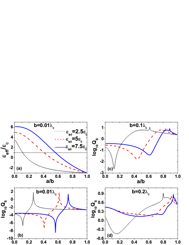
Of particular interest is that significant reduction arises if we tune the value of εsθsubscript𝜀𝑠𝜃\varepsilon_{s\theta} in the shell. In Fig. 2(c), with decreasing εsθsubscript𝜀𝑠𝜃\varepsilon_{s\theta} (i.e., be reduced to 2.5ε0subscript𝜀0\varepsilon_{0}), the scattering efficiency can be reduced considerably, and thus the transparency or nearly “invisible” is attained for large objects. Fig. 2(d) have verified this tendency at an even larger size. In other words, through adjusting the dielectric anisotropy of the shell, it is helpful for us to realize much lower scattering cross section and better electromagnetic invisibility. Moreover, the near-zero scattering radius ratio can be tuned at the same time. We note that a resonant peak is also presented in Fig. 2, in the long wavelength limit (or for small size), the maximum of scattering is due to the resonance of D±1TMsuperscriptsubscript𝐷plus-or-minus1𝑇𝑀D_{\pm 1}^{TM}. In comparison with the small objects, the additional small peaks in Fig. 2(c) and (d) result from the contributions of D±2TMsuperscriptsubscript𝐷plus-or-minus2𝑇𝑀D_{\pm 2}^{TM} because the higher terms of the scattering coefficient cannot be neglected due to the increasing size of the objects.

Refer to caption
Figure 3: (a) The effective permittivity εeffsubscript𝜀𝑒𝑓𝑓\varepsilon_{eff} of the coated cylinder versus core-shell ratio for different εcθsubscript𝜀𝑐𝜃\varepsilon_{c\theta} when b=0.01λ0𝑏0.01subscript𝜆0b=0.01\lambda_{0}. (b)-(c) the scattering efficiency versus core-shell ratio for different values of b and different εcθsubscript𝜀𝑐𝜃\varepsilon_{c\theta}. The values of εcθsubscript𝜀𝑐𝜃\varepsilon_{c\theta} in (a)-(c) are: εcθ=6ε0subscript𝜀𝑐𝜃6subscript𝜀0\varepsilon_{c\theta}=-6\varepsilon_{0} (black dotted line); εcθ=5ε0subscript𝜀𝑐𝜃5subscript𝜀0\varepsilon_{c\theta}=-5\varepsilon_{0} (red dashed line); εcθ=2ε0subscript𝜀𝑐𝜃2subscript𝜀0\varepsilon_{c\theta}=-2\varepsilon_{0} (blue solid line), while other parameters in (a-c) are εcr=5ε0,εsθ=εsr=6ε0,μsz=μcz=μ0formulae-sequenceformulae-sequencesubscript𝜀𝑐𝑟5subscript𝜀0subscript𝜀𝑠𝜃subscript𝜀𝑠𝑟6subscript𝜀0subscript𝜇𝑠𝑧subscript𝜇𝑐𝑧subscript𝜇0\varepsilon_{cr}=-5\varepsilon_{0},\quad\varepsilon_{s\theta}=\varepsilon_{sr}=6\varepsilon_{0},\quad\mu_{sz}=\mu_{cz}=\mu_{0}. (d) the full-wave scattering efficiency versus core-shell ratio for b=0.1λ0𝑏0.1subscript𝜆0b=0.1\lambda_{0} with εcθ=2ε0subscript𝜀𝑐𝜃2subscript𝜀0\varepsilon_{c\theta}=2\varepsilon_{0} (black dotted line), εcθ=5ε0subscript𝜀𝑐𝜃5subscript𝜀0\varepsilon_{c\theta}=5\varepsilon_{0} (red dashed line), and εcθ=12ε0subscript𝜀𝑐𝜃12subscript𝜀0\varepsilon_{c\theta}=12\varepsilon_{0} (blue solid line), while the other parameters are εcr=5ε0,εsθ=εsr=10ε0,μsz=μcz=μ0formulae-sequenceformulae-sequencesubscript𝜀𝑐𝑟5subscript𝜀0subscript𝜀𝑠𝜃subscript𝜀𝑠𝑟10subscript𝜀0subscript𝜇𝑠𝑧subscript𝜇𝑐𝑧subscript𝜇0\varepsilon_{cr}=5\varepsilon_{0},\quad\varepsilon_{s\theta}=\varepsilon_{sr}=-10\varepsilon_{0},\quad\mu_{sz}=\mu_{cz}=\mu_{0}.

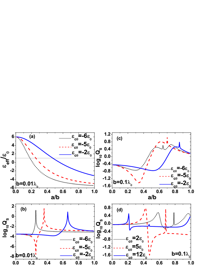
Next, we consider a coated cylinder with radially anisotropic core but isotropic shell as shown in Fig. 3. Again, for a small coated cylinder, it is evident that the minimum of the scattering cross section takes place at the core-shell radius ratio determined by the condition εeff=ε0subscript𝜀𝑒𝑓𝑓subscript𝜀0\varepsilon_{eff}=\varepsilon_{0}. Hence the results based on the full-wave theory should be in accordance with those from effective medium theory. We can observed from Figs. 3(b-d) that the isotropic core results in the smallest scattering efficiency, i.e., better electromagnetic invisibility (e.g., red dashed curves in Figs. 3 representing isotropic cores in each case). This fact is further proved for larger sizes (see Fig. 3(c) and Fig. 3(d)), and even for either plasmonic core with dielectric shell (see Fig. 3(c)) or dielectric core with plasmonic shell (see Fig. 3(d)). It reveals that in the core-shell system incorprating radial anisotropy, the isotropy in the core is a better choice to minimize the scattering width, resulting in “good” invisibility.

Refer to caption
Figure 4: The full-wave scattering efficiency versus core-shell ratio for b=0.2λ0𝑏0.2subscript𝜆0b=0.2\lambda_{0}. Parameters for the black dotted curve: εcθ=εcr=3ε0,εsθ=2.5ε0,εsr=5ε0,μsz=μcz=μ0formulae-sequencesubscript𝜀𝑐𝜃subscript𝜀𝑐𝑟3subscript𝜀0formulae-sequencesubscript𝜀𝑠𝜃2.5subscript𝜀0formulae-sequencesubscript𝜀𝑠𝑟5subscript𝜀0subscript𝜇𝑠𝑧subscript𝜇𝑐𝑧subscript𝜇0\varepsilon_{c\theta}=\varepsilon_{cr}=-3\varepsilon_{0},\quad\varepsilon_{s\theta}=2.5\varepsilon_{0},\quad\varepsilon_{sr}=5\varepsilon_{0},\quad\mu_{sz}=\mu_{cz}=\mu_{0}. Parameters for the red solid curve εcθ=εcr=3ε0,εsθ=2.5ε0,εsr=5ε0,μsz=0.5μ0,μcz=7μ0formulae-sequencesubscript𝜀𝑐𝜃subscript𝜀𝑐𝑟3subscript𝜀0formulae-sequencesubscript𝜀𝑠𝜃2.5subscript𝜀0formulae-sequencesubscript𝜀𝑠𝑟5subscript𝜀0formulae-sequencesubscript𝜇𝑠𝑧0.5subscript𝜇0subscript𝜇𝑐𝑧7subscript𝜇0\varepsilon_{c\theta}=\varepsilon_{cr}=-3\varepsilon_{0},\quad\varepsilon_{s\theta}=2.5\varepsilon_{0},\quad\varepsilon_{sr}=5\varepsilon_{0},\quad\mu_{sz}=0.5\mu_{0},\quad\mu_{cz}=-7\mu_{0}.

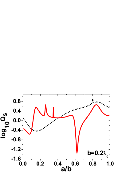
It is known that for large coated objects, multipolar terms contribute to the scattering cross section, and the coated cylinder is visible for almost all the radius ratio (see Fig. (4)). In order to make the coated cylinder transparent or at least less visbile, one can further adjust the magnetic anisotropy to reduce the scattering cross section. From Fig. 4, we can conclude that the invisibility effectiveness of large objects can be greatly improved through suitable adjustment of both the dielectric and magnetic anisotropy and the scattering efficiency can be reduced for nearly one order in magnitude.

Refer to caption
Figure 5: Snapshots of the real part of total Hzsubscript𝐻𝑧H_{z} fields distribution in the xy𝑥𝑦xy plane around the coated cylinder with outer radius b=0.2λ0𝑏0.2subscript𝜆0b=0.2\lambda_{0} at 0.3GHz. (a) Parameters are: εcθ=εcr=3ε0,εsθ=5ε0,εsr=5ε0,μsz=μcz=μ0formulae-sequencesubscript𝜀𝑐𝜃subscript𝜀𝑐𝑟3subscript𝜀0formulae-sequencesubscript𝜀𝑠𝜃5subscript𝜀0formulae-sequencesubscript𝜀𝑠𝑟5subscript𝜀0subscript𝜇𝑠𝑧subscript𝜇𝑐𝑧subscript𝜇0\varepsilon_{c\theta}=\varepsilon_{cr}=-3\varepsilon_{0},\quad\varepsilon_{s\theta}=5\varepsilon_{0},\quad\varepsilon_{sr}=5\varepsilon_{0},\quad\mu_{sz}=\mu_{cz}=\mu_{0}, a=0.645b𝑎0.645𝑏a=0.645b. (b)Parameters are: εcθ=εcr=3ε0,εsθ=2.5ε0,εsr=5ε0,μsz=μcz=μ0formulae-sequencesubscript𝜀𝑐𝜃subscript𝜀𝑐𝑟3subscript𝜀0formulae-sequencesubscript𝜀𝑠𝜃2.5subscript𝜀0formulae-sequencesubscript𝜀𝑠𝑟5subscript𝜀0subscript𝜇𝑠𝑧subscript𝜇𝑐𝑧subscript𝜇0\varepsilon_{c\theta}=\varepsilon_{cr}=-3\varepsilon_{0},\quad\varepsilon_{s\theta}=2.5\varepsilon_{0},\quad\varepsilon_{sr}=5\varepsilon_{0},\quad\mu_{sz}=\mu_{cz}=\mu_{0}, a=0.155b𝑎0.155𝑏a=0.155b. (c) Parameters are: εcθ=εcr=3ε0,εsθ=2.5ε0,εsr=5ε0,μsz=0.5μ0,μcz=7μ0formulae-sequencesubscript𝜀𝑐𝜃subscript𝜀𝑐𝑟3subscript𝜀0formulae-sequencesubscript𝜀𝑠𝜃2.5subscript𝜀0formulae-sequencesubscript𝜀𝑠𝑟5subscript𝜀0formulae-sequencesubscript𝜇𝑠𝑧0.5subscript𝜇0subscript𝜇𝑐𝑧7subscript𝜇0\varepsilon_{c\theta}=\varepsilon_{cr}=-3\varepsilon_{0},\quad\varepsilon_{s\theta}=2.5\varepsilon_{0},\quad\varepsilon_{sr}=5\varepsilon_{0},\quad\mu_{sz}=0.5\mu_{0},\quad\mu_{cz}=-7\mu_{0}, a=0.62b𝑎0.62𝑏a=0.62b.

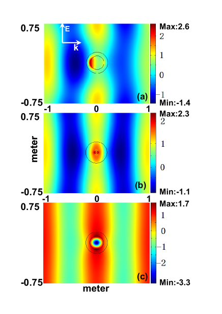
If the size is sufficiently small, the core-shell ratio determined by the cloaking condition definitely results in better invisibility performance. In order to demonstrate the invisibility performance for a large size b=0.2λ0𝑏0.2subscript𝜆0b=0.2\lambda_{0} improved by the adjustment of the magnetodielectric anisotropy, we present the patterns of magnetic field in the xy𝑥𝑦xy plane, calculated by finite-element solver of the Comsol Multiphysics. In Fig. 5(a), for the isotropic case (the same parameters as the red dashed line in Fig. 2(d)), there exists noticeable perturbation caused by the scattered field. Comparing Fig. 5(b) with 5(a), one can see that the perturbation is reduced through adjusting the anisotropic permittivity of the shell. If we take the permeability into account and properly tune its value, the near “invisibility” could be achieved for even relatively larger objects. In Fig. 5(c), the incident wave is almost unaltered outside the shelled cylinder, as if there was no scatterer. The specific core-shell ratios chosen in Fig. 5 are based on the given material parameters, and obtained in numerical calculation for the lowest scattering efficiency correspondingly instead of theoretical effective medium theory (due to the size constraint). It should be mentioned that the transparency mechanism in this paper is different from the ideal cloak proposed by Pendry Pendry via spatical compression, where there is no EM field in the core cylinder. Here the coated cylinder is penetrable.

V Conclusion

In summary, we have demonstrated the full-wave scattering theory by magnetodielectric anisotropic coated cylinder of infinite length normally illuminated by a TM polarized plane wave. The effective permittivity and permeability of the anisotropic coated cylinder have also been derived in long wavelength limit. The non-scattering radius ratio obtained from the full-wave theory for small objects can be well described within the effective medium theory. Numerical results have shown that the effective scattering width csca=2bQscasubscript𝑐𝑠𝑐𝑎2𝑏subscript𝑄𝑠𝑐𝑎c_{sca}=2bQ_{sca} can be significantly reduced by adjusting the anisotropic permittivity of the shell, so as to achieve better transparency. However it is found that tuning the core anisotropy is not able to improve the efficiency of transparency. Furthermore, we could further improve the invisibility performance of the cylindrical objects by the adjustment of both electric and magnetic anisotropies. Although we have only considered the 2D case and losses materials, our research may be useful for the design of low-observability cylindrical targets. Based on the above investigation, we may extend our investigation to more general situations, such as obliquely incidence with arbitrary polarization, and finite-long cylinders. We could scale well towards the research of making multiple cylindrical objects “invisible”.

Acknowledgments

This work was supported by the National Natural Science Foundation of China under Grant No. 10674098, the National Basic Research Program under Grant No. 2004CB719801, the Key Project in Science and Technology Innovation Cultivation Program of Soochow University, and the Natural Science of Jiangsu Province under Grant No. BK2007046.

References

  • (1) J. B. Pendry, D. Schurig, and D. R. Smith, “Controlling electromagnetic fields,” Sci., vol. 312, pp. 1780-1782, June 2006.
  • (2) U. Leonhardt, “Optical conformal mapping,” Sci., vol. 312, pp. 1777-1780. June 2006.
  • (3) S. A. Cummer, B.-I. Popa, D. Schurig, D. R. Smith, and J. B. Pendry, “Full-wave simulations of electromagnetic cloaking structures,” Phys. Rev. E, vol. 74, vol. 3, pp. 036621, Sept. 2006.
  • (4) Y. Zhao, C. Argyropoulos, and Y. Hao, “Full-wave finite-difference time-domain simulation of electromagnetic cloaking structures,” Opt. Express, vol. 16, no. 9, pp. 6717-6730, Apr. 2008.
  • (5) D. Schurig, J. J. Mock, B. J. Justice, S. A. Cummer, J. B. Pendry, A. F.Starr, and D. R. Smith, “Metamaterial electromagnetic cloak at microwave frequencies,” Sci., vol. 314, pp. 977-980, Nov. 2006.
  • (6) W. Cai, U. K. Chettiar, A. V. Kildishev, and V. M. Shalaev, “Optical cloaking with metamaterials,” Nat. Photon. vol. 1, pp. 224-227, Apr. 2007.
  • (7) Z. Ruan, M. Yan, C. W. Neff, and M. Qiu, “Ideal cylindrical cloak: perfect but sensitive to tiny perturbations,” Phys. Rev. Lett., vol. 99, vol. 11, pp. 113903, Sept. 2007.
  • (8) H. S. Chen, B. I. Wu, B. L. Zhang, and J. A. Kong, “Electromagnetic wave interactions with a metamaterial cloak,” Phys. Rev. Lett., vol. 99, no. 6, pp. 063903, Aug. 2007.
  • (9) W. Jiang, T. Cui, X. Yang, Q. Cheng, R. Liu, and D. Smith, “Invisibility cloak without singularity,” Appl. Phys. Lett., vol. 93, no. 19, pp. 194102, Nov. 2008.
  • (10) D. H. Kwon, and D. H. Werner, “Two-dimensional eccentric electromagnetic cloaks,” Appl. Phys. Lett., vol. 92, no. 1, pp. 013505, Jan. 2008.
  • (11) M. Rahm, D. Schurig, D. A. Roberts, S. A. Cummer, D. R. Smith, and J. B. Pendry, “Design of electromagnetic cloaks and concentrators using form-invariant coordinate transformations of Maxwell’s equations,” Photon. Nanostruct.: Fundam. Applic., vol. 6, no. 1, pp. 87-95, Apr. 2008.
  • (12) H. Ma, S. Qu, Z. Xu, and J. Wang, “Numerical method for designing approximate cloaks with arbitrary shapes,” Phys. Rev. E, vol. 78, no. 3, pp. 036608, June 2008.
  • (13) A. Alú, and N. Engheta, “Achieving transparency with plasmonic and metamaterial coatings,” Phys. Rev. E, vol, 72, no. 1, pp. 016623, July 2005.
  • (14) M. G. Silveirinha, A. Alú, and N. Engheta, “Parallel-plate metamaterials for cloaking structures,” Phys. Rev. E, vol. 75, no. 3, pp. 036603, Mar. 2007.
  • (15) L. Gao, T. H. Fung, K. W. Yu, and C. W. Qiu, “Electromagnetic transparency by coated spheres with radial anisotropy,” Phys. Rev. E, vol. 78, no. 4, pp. 046609, Oct. 2008.
  • (16) C. W. Qiu, L. Hu, X. Xu, and Y. Feng, “Spherical cloaking with homogeneous isotropic multilayered structures,” Phys. Rev. E, vol. 79, pp. 047602, Aug. 2009.
  • (17) M. Yan, Z. Ruan, and M. Qiu, “Scattering characteristics of simplified cylindrical invisibility cloaks,” Opt. Express vol, 15, no. 26, pp. 17772-17782, Dec. 2007.
  • (18) Y. Luo, J. Zhang, H. Chen, S. Xi, and Bae-Ian Wu, “Cylindrical cloak with axial permittivity/permeability spatially invariant,” Appl. Phys. Lett., vol, 93, pp. 033504, July 2008.
  • (19) P. L. E. Uslenghi and R. D. Graglia, “Electromagnetic scattering from anisotropic materials, Part I: General theory,” IEEE Trans. Antennas Propag., vol. 32, no. 8, pp. 867–869, Aug. 1984.
  • (20) R. D. Graglia and P. L. E. Uslenghi, “Electromagnetic scattering from anisotropic materials, Part II: Computer code and numerical results in two dimensions,” IEEE Trans. Antennas Propag., vol. 35, no. 2, pp. 225–232, Feb. 1987.
  • (21) J. C. Monzon and N. J. Damaskos, “Two-dimensional scattering by a homogeneous anisotropic rod,” IEEE Trans. Antennas Propagat., vol. 34, no. 10, pp. 1243–1249, Oct. 1986.
  • (22) J. C. Monzon, “Three-dimensional scattering by an infinite homogeneous anisotropic circular cylinder - A spectral approach,” IEEE Trans. Antennas Propag., vol. 35, no. 6, pp. 670–682, June 1987.
  • (23) B. Beker, K. R. Umashankar, and A. Taflove, “Numerical analysis and validation of the combined field surface integral equations for electromagnetic scattering by arbitrary shaped two-dimensional anisotropic objects,” IEEE Trans. Antennas Propagat., vol. 37, no. 12, pp. 1573–1581, Dec. 1989.
  • (24) C. T. Tai, Dyadic Green’s Functions in Electromagnetic Theory, IEEE Press, Piscataway, New Jersey, The 2nd edition, 1994.
  • (25) N. K. Uzunoglu, P. G. Gottis, and J. G. Fikioris, “Excitation of electromagnetic waves in a gyroelectric cylinder,” IEEE Trans. Antennas Propag., vol. 33, no. 1, pp. 90–99, Jan. 1995.
  • (26) C. W. Qiu, L. W. Li, H. Yao, and S. Zouhdi, “Properties of Faraday chiral media: Green dyadics and negative refraction,” Phys. Rev. B, vol. 74, no. 11, pp. 115110, 2006.
  • (27) C. W. Qiu, S. Zouhdi, and A. Razek, “Modified spherical wave functions with anisotropy ratio: Application to the analysis of scattering by multilayered anisotropic shells,” IEEE Trans. Antennas Propag., vol. 55, no. 12, pp. 3515–3523, Dec. 2007.
  • (28) H. C. van de Hulst, Light Scattering by Small Particles, John Wiley & Sons, New York, 1957.
  • (29) Y. Wu, J. S. Li, Z. Q. Zhang, and C. T. Chan, “Effective medium theory for magnetodielectric composites: beyond the long-wavelength limit,” Phys. Rev. B, vol. 74, no. 8, pp. 085111, Aug. 2006.
  • (30) B. S. Luk’yanchuk, and V. Ternovsky, “Light scattering by a thin wire with a surface-plasmon resonance: bifurcations of the poynting vector field,” Phys. Rev. B, vol. 73, no. 23, pp. 235432, June 2006.
  • (31) J. D. Jackson, Classical Electrodynamics, Wiley, New York, The 3rd edition, 1999.