Electrical and Kinetic Model of an Atmospheric RF Device for Plasma Aerodynamics Applications
Abstract
The asymmetrically mounted flat plasma actuator is studied using a self-consistent 2-DIM fluid model at atmospheric pressure. The computational model use the drift-diffusion approximation and a simple plasma phenomenological kinetic model. It is investigated its electrical and kinetic properties, and calculated the charged species concentrations, surface charge density, electrohydrodynamic forces and gas speed. The present computational model contributes to understand the main physical mechanisms and methods to improve its performance.
pacs:
47.65.-d, 52.80.Pi, 51.50.Bv, 07.05.Tp, 47.85.LAI Introduction
There has been a growing interest in the field of plasma aerodynamics related to its outstanding importance in active flow control, overriding the use of mechanical flaps Colver_96 ; Roth_03 ; Pinheiro_06 ; Moreau_07 . Plasma actuators create a plasma above a blunt body that modify the laminar-turbulent transition inside the boundary layer Soldati_98 ; Soldati_99 , even at a high angle of attack Roth_03 ; 8 they induce or reduce the fluid separation, and thus reducing drag Colver_96 and increasing lift 9 ; 10 ; 11 . They also allow sonic boom minimization schemes Sigelman_70 ; Boyd_99 , avoiding unwanted vibrations or noise 12 ; 13 , sterilizing or decontaminating surfaces and even frost removal 14 on any airfoil, jet engine or wind turbine, through pure electromagnetic control. Its promising potential extend to flow control at hypersonic speeds Shin_07 ; Utkin_07 (while still using a jet-reaction aircraft propeller).
The asymmetric dielectric barrier discharge (DBD) plasma actuator is a normal glow discharge that, like all normal glow discharges, operates at the Stoletow point. This guarantees that the generation of the ion-electron pairs at one atmosphere is done efficiently. In air, the minimum energy cost is 81 electron volts per ion-electron pair formed in the plasma. In plasma torches, this energy cost can be of the order of one keVion-electron pair; in arcs, it can range from 10 to 50 keVion-electron pair.
Particle and fluid simulations have been done 1 ; 2 ; 4 for a plasma actuator in pure oxygen and pure nitrogen showing the formation of an asymmetrical force that accelerates the ions dragging the neutral fluid in the direction of the buried electrode. A net force arises because the plasma density, and consequently, momentum transfer are greater during the second half of the bias cycle, due partially to the ion density greater a factor of 10 times during the second half-cycle. Thus, in each cycle there is created a total unidirectional force towards the buried electrode that can create neutral fluid flow velocities on the order of 8 ms.
Two dimensional fluid models of a DBD plasma actuator have been made 5 ; 6 which calculate the total force on ions and neutral particles and show that the force generated is of the same nature as the electric wind in a corona discharge, with the difference that the force in the DBD is localized in the cathode sheath region of the discharge and expands along the dielectric surface. While the intensity of this force is much larger than the existing force of a dc corona discharge, it is active during less than a hundred nanoseconds for each discharge pulse and, consequently, the time averaged forces are of the same magnitude in both cases.
The use of voltage pulses in plasma actuators, by modulation of the high frequency excitation voltage carrier wave by a square wave, introduces mean and unsteady velocity components and thus the air momentum is composed of both time-mean and oscillatory components of momentum, the overall effect improving momentum efficiency 15 .
Actuators placed on the leading edge of an airfoil can control the boundary layer separation, while if located at the trailing edge can control lift 4 . Enloe et al. Enloe_03 ; Enloe_06 have found experimentally that the thrust and maximum induced speed are proportional to the input power , which depends nonlinearly on the voltage drop across the dielectric .
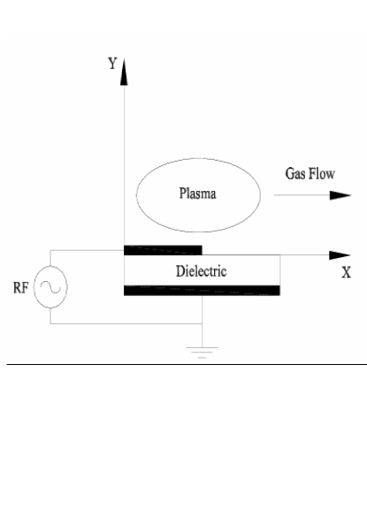
The aim of this paper is to present a self-consistent two dimensional modeling of the temporal and spatial development of asymmetric DBD plasma actuator using an EHD code (CODEHD) developed in our group. The computational model solves the governing equation in the drift-diffusion approximation and a plasma phenomenological kinetic model. Fig. 1 shows the rather simple configuration of the plasma actuator in coplanar configuration.
II Numerical model
II.1 Description
At our knowledge the first comprehensive kinetic model of a dielectric barrier discharge plasma actuator was published by Singh et al. Singh . Gadri Gadri has shown that an atmospheric glow discharge is characterized by the same phenomenology as low-pressure dc glow discharge. To subdue numerical complexity no detailed plasma chemistry with neutral heavy species is presently addressed. At this stage it is only considered the kinetics involving electrically charged species supposedly playing a determinant role at atmospheric pressure: N, N, O, O, and electrons. From the charged species populations and as well the electric field controlling their dynamics, it can be studied electrohydrodynamics (EHD) with interest to plasma actuators, like the body forces acting on the plasma horizontally (neutral flow control) and perpendicularly (boundary-layer control) to the energized electrode; and the neutral particles average speed.
The applied voltage has a sinusoidal wave form , where the root mean square voltage, , in this case of study is 5 kV and the applied frequency is kHz. Therefore, the dynamical time is s.
The plasma actuator simulation domain is a 2-Dim Cartesian geometry with the total length along the Ox-axis mm and height mm. It consists of conductive copper strips (with negligible thickness) of width mm, separated by a 0.065 cm thick dielectric with width equal to 3 mm and relative dielectric permittivity . The electrical capacity of the reactor is given by the conventional formula .
II.2 Transport parameters and rate coefficients
The working gas is a “airlike” mixture of a fixed fraction of nitrogen ([NN) and oxygen ([ON), as is normally present at sea level at . The electron homogeneous Boltzmann equation is solved with the 2-term expansion in spherical harmonics Ferreira for a mixture of NO2(22), assumed thoroughly constant. The gas temperature is also assumed constant, both spatially and in time frame, with K, and the same applies to the vibrational temperature of nitrogen K and oxygen K. This assumption avoids the need of a more complex vibrational kinetic model.
Using the set of cross sections of excitation by electron impact taken from Ref. Siglo rates coefficients and transport parameters needed for the electronic kinetics are obtained. So far, the species included in the present model are the following: , , , and electrons. Remark that at 1 atm the concentrations of ions need to be introduced since they are bigger than , due partially to the reaction , which occurs at a higher rate than the direct ionization. Also, notice that at Torr loss by ambipolar diffusion becomes overwhelming important. Ion diffusion and mobility coefficients were taken from the Report Sigmond : V-1 m-1 s-1 (on the range of E/N with interest here), V-1 m-1 s-1, and V-1 m-1s-1. The gas density at atm and assuming K is .
At atmospheric pressure the local equilibrium assumption holds and the transport coefficients (, , , , , ) depend on space and time only through the local value of the electric field ; this is the so called hydrodynamic regime.
To avoid the use of Navier-Stokes equations and to obtain a faster numerical solution of the present hydrodynamic problem it is assumed that the gas flow does not alter the plasma characteristics and is much smaller than the charged particle drift velocity. This assumption allows a simplified description of the flow.
With the above assumptions charged species can be described by continuity equations and momentum transport equations in the drift-diffusion approximation. This last approximation is valid if their drift energy is negligible with respect to thermal energy. Also, in the drift-diffusion equation it is neglected the temperature gradient term (e.g., Ref. 6 ).
| Kind of reaction | Process | Rate coefficient |
|---|---|---|
| Ionization | 111Numerical data obtained by solving the quasi-stationary, homogeneous electron Boltzmann equation. See Ref. Ferreira for details. | |
| Ionization | 111Numerical data obtained by solving the quasi-stationary, homogeneous electron Boltzmann equation. See Ref. Ferreira for details. | |
| 3-body electron attachment | (cms) 222With . | |
| 3-body electron attachment | (cms) 333With . | |
| Collisional detachment | (cms) | |
| e-ion dissociative recombination | (cms) | |
| e-ion dissociative recombination | (cms) | |
| 2-body ion-ion recombination | (cms) | |
| 2-body ion-ion recombination | (cms) | |
| Ion-conversion | (cms) | |
| Recombination | ||
| Ion-conversion | (cms) |
The reactions included in the present “effective” kinetic model are listed in Table 1. It is assumed that all volume ionization is due to electron-impact ionization from the ground state and the kinetic set consists basically in ionization, attachment and recombination processes. The kinetics of excited states and heavy neutral species is not considered, particularly the possible important role of metastable species (certainly improving plasma density through Penning ionization Massines_99 ) and nitrous oxide (poisoning gas) are neglected. The major drawback associated to the present “effective” kinetic model is the lack of consistency due to the neglect of atomic species, but it allows to investigate the general trends of the plasma actuator operating characteristics.

For more concise notation, we put ; ; ; , and .
With the above assumptions charged species can be described by continuity equations and momentum transport equations in the drift-diffusion approximation. This last approximation is valid if their drift energy is negligible with respect to thermal energy. Also, in the drift-diffusion equation it is neglected the temperature gradient term.
II.3 Numerical model
The particle’s governing equations are of convection-diffusion type and they are solved using a well-known finite-element method proposed by Patankar Patankar . Poisson equation for the electric field is solved applying the successive over-relaxation method (SOR) for boundary-value problem. The chosen time step is limited by the value of the dielectric relaxation time. For the present calculations it was used (100x100) computational meshes. The entire set of equations are integrated successively in time supposing the electric field constant during each time step, obtaining a new value of the electric field after the end of each time step. The method used to integrate the continuity equations and Poisson equation was assured to be numerically stable, constraining the time step width to the well known Courant-Levy-Friedrich stability criterion.

The governing equation for N (at atmospheric pressure the nitrogen ion predominant is N) is:
| (1) |
The governing equation for N (one of the most mobile charged specie in the plasma) is:
| (2) |
The oxygen positive ion considered is O and its resultant governing equation is given by:
| (3) |
The negative ion O was introduced (due to high electronegativity of oxygen), and its governing equation was written as:
| (4) |
Finally, the governing equation for electrons can be written in the form:
| (5) |
Photo-ionization was not included as a non-local secondary effect.
In order to avoid the use of Navier-Stokes equation, the drift-diffusion approximation for the charged particle mean velocities appearing in the continuity equations is used instead:
| (6) |
Here, and represent the charged particle mobility and the respective diffusion coefficient. The applied voltage has a sinusoidal wave form:
| (7) |
where is the dc bias voltage (although here we fixed to ground, ) and is the applied angular frequency. is the maximum amplitude with the root mean square voltage in this case of study kV and the applied frequency kHz.
In an RF discharge the calculation of the displacement current is a not a simple matter. However, the total current (convective plus displacement current) was determined using the following equation given by Sato and Murray Sato :
| (8) |
where is the volume occupied by the discharge, is the space-charge free component of the electric field. The last integral when applied to our geometry gives the displacement current component
| (9) |
We assume throughout the calculations since Auger electrons are assumed to be produced by impact of positive ions on the cathode with such an efficiency. Hence, the flux density of secondary electrons out of the cathode is given by
| (10) |
with denoting the flux density of positive ions. Secondary electron emission plays a fundamental role on the working of the asymmetric DBD plasma actuator. The progressive accumulation of electric charges over the dielectric surface develops a so-called “memory voltage”, whose expression is given by:
| (11) |
Here, is the equivalent capacitance of the discharge.
As charged particles are produced in the plasma volume, it is calculated the space-charge electric field by solving the Poisson equation coupled the particle’s governing equations:
| (12) |
We assumed the following boundary conditions:
-
•
over the electrode (Dirichlet boundary condition): ;
-
•
over the insulator (Neumann boundary condition): .
The flux of electric charges impinging on the dielectric surface builds up a surface charge density which was calculated by balancing the flux to the dielectric and it is governed by
| (13) |
Here, and represent the normal component of the flux of positive and negative ions and electrons to the dielectric surface. Furthermore, it is assumed that ions and electrons recombine instantaneously on the perfectly absorbing surface. As it will be discussed later, this simplified assumption constitute a drawback of the present model.
The entire set of equations were solved together self-consistently at each 1 ns time step, as illustrated with the program flow chart shown in Fig. 2.
III Results
The electrohydrodynamic area of research has grown to a large extent lately, but it still remains to achieve a better understanding on how the charged particles transfer momentum to neutrals, and what physical limitations restrain the applicability of this device for boundary control and neutral flow propulsion.
The simulations were done for a two-dimensional flat staggered geometry, while assuming the plasma homogeneous along the OZ-axis (see Fig. 1). This is essentially a “surface discharge” arrangement with asymmetric electrodes.
III.1 Electrical characteristics
Fig. 3 shows the evolution along a full period of the calculated electric current (convective plus displacement currents), applied voltage, gas voltage and memory voltage. A stationary solution of the entire set of equations modeling the apparatus is achieved typically after 4-5 cycles with CODEHD. With the assumed conditions at about 700 Volts (or Volts) electron avalanches develop (the first avalanches occur in the gas gap), replenishing the volume above the surface with charged particles. In a coplanar discharge, the current density increases with the applied voltage and almost nearly with the permittivity Gibalov_04 .
This corresponds to roughly kVcm, when the theoretical dielectric breakdown of air is 30 kVcm. Hence, the charged particles flowing to the dielectric surface start accumulating on the surface, building-up an electric field that prevents the occurrence of a high current, and therefore quenching the discharge development at an early stage. At about 3 s develops the first avalanche. The pulse form is typical: the first peak corresponds to the arrival of fast electrons to the electrode and it corresponds to the instant when the electric field is maximal; afterwards, the pulse slowly fade out, due to the dielectric charging and consequent decrease of the electric field.
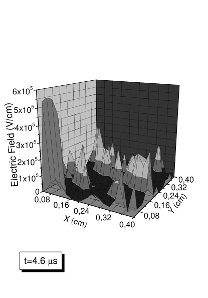
Also, from Fig. 4 it is clear that the electric field has a maximum peak at the edge of the exposed (and energized) electrode. From this edge the successive streamers (current pulses) are initiated.
At 4 cycle the transient regime is totally damped and the electrical characteristics stabilize. During the first (positive) half-cycle electrons and negative ions are formed above the dielectric surface, which acts as a virtual cathode (buried below the dielectric), while they are pushed by the electric field towards the positive (energized) electrode located on the top of the dielectric playing the role of the anode, as can be seen from the set of snapshots shown from Figs. 6 and 7. The dielectric surface is progressively charged.

Fig. 5 shows the surface charge density vs. time, for the case of a larger dielectric width. The charge density should be of the order Cm2, since , or . It becomes increasingly negative during the first half-cycle and tends to reverse sign during the second half-cycle. The memory voltage is regulated by the surface charge density deposited over the dielectric by the successive streamers. Notice that when the energized electrode is negative, more streamers occur.
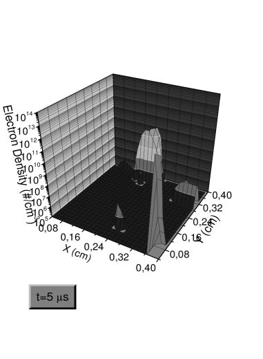
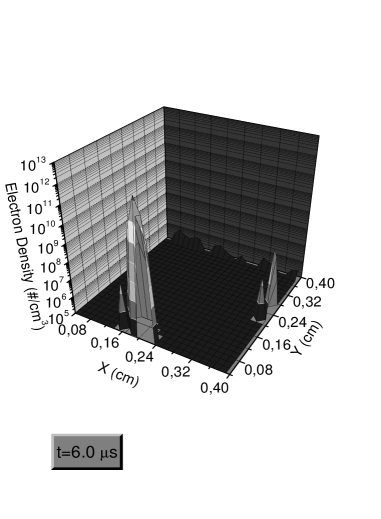
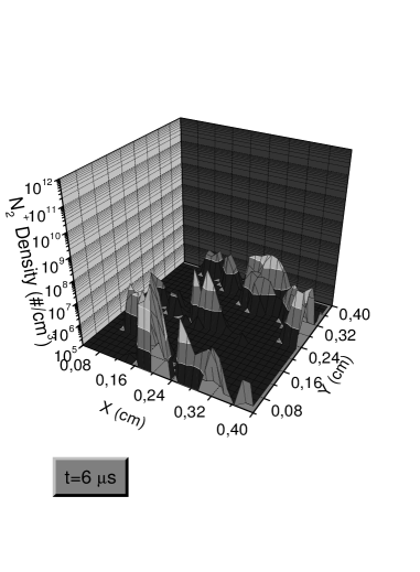
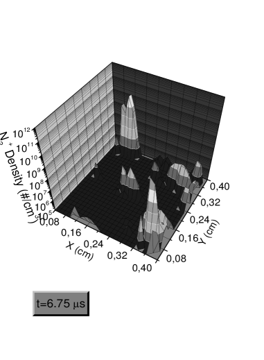
Fig. 6 shows a snapshot of the electrons density along time since the beginning of an electron streamer occurring during the first-half cycle. The density profiles were obtained after 4-5 cycles with the dielectric charging onset resulting in the formation of a virtual negative electrode. Electrons are driven along the electric field lines toward the anode (the energized electrode at the first-half cycle).
At the same time and in the reversed direction a streamer of positive ions are driven to the cathode, as it is shown at the time series illustrated in Fig. 7. During the streamers ponderomotive forces attain their highest magnitude. The event occurring at the instant of time s portrays the arrival of ions N to the virtual cathode.
We notice that the ions are mainly created in volume and are immediately driven to the virtual cathode, while an average number of them are retained nearby the anode decreasing almost linearly with distance from the energized electrode surface. Thus, it is clear that the propagation of the electron avalanche near (and above) the dielectric surface is of considerable importance, dictating the strength of the body forces and gas speed.
Conditions for maximizing ion-driven gas flow were obtained by Rickard et al. Rickard_06 , and they concluded that, irrespective of geometry, ponderomotive forces on the gas are maximized by increasing current density and by decreasing mobility (i.e., charge carriers which exercise highest drag on the neutral gas). Therefore, ions seem to be the best candidate for this purpose.
Our numerical model shows that when the present conditions prevail, heavy species such as N move more slowly with the varying external electric field. In fact, the most actives species on the process of momentum transfer are the electrons and N, but the molecular ions due to their mass contribute in majority to control the boundary layer and propulsive force.
From Fig. 7 it is noticeable the multiplications of N ions when flowing from the electrode edge to the dielectric surface, flowing along the reverse way as electrons did. The ions feeding along the dielectric surface is due to a relative bigger dielectric width which favors the increase of the ions swarm Khudik , and thus increasing the gas speed due to the momentum exchange onset from charged particles to neutrals. Notice that at s nitrogen ions leave the region at the boundary between the electrode and the dielectric, which corresponds a region of maximum electric field (see Fig. 4).
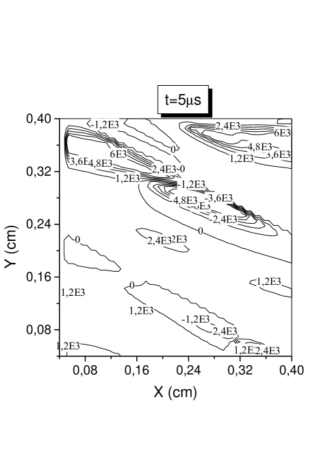
Fig. 8 shows contours of constant potential at s. We can see the decrease of the potential above the energized electrode and a field reversal region toward the dielectric side (with the negative electrode below). The negative glow remains in the proximity of this region, while a second region of field reversal is also momentously observed. The region of negative electric potential that appears at 5 s in the first half-cycle is due to the presence of an excess of negative charge due to O ions, while the region of maximal electric potential has as field source all others positive ions. Numerical simulations have shown that while negative ions in the air do not contribute significantly to the ponderomotive forces, they can play a role in the discharge working Enloe_06 . Another major structure of the normal glow discharge remains above with higher values of the potential. Hence, the phenomenology and typical structures developed by normal glow discharge are also displayed by the OAUGDPTM. These aspects were also shown in previous publications, like the one-dimensional numerical simulations of the OAUGDPTM done by Ben Gadri Gadri ; Rahel and fast photography obtained by Massines et al. Massines .
Hence, the field reversals observed have the strong contribution of the negative ions O which are thus playing an important role in the discharge working, since it is well known that field reversal location decides the fraction of ions to the cathode and the magnitude of the plasma maximum density Boeuf_95 ; Kolobov ; Pinheiro_06 ; Pinheiro .
The EHD force acting on the charged particles is given by 1 ; 6 :
| (14) |
where and are respectively the ion and electron number density; and are the electron and ion mean velocities; is the charged particle production rate. The last term of Eq. 14 is here neglected, since its importance confines to other phenomena such as electrophoresis and cathophoresis Boeuf_05 , and its contribution to the induced velocity is smaller due to the very small electronneutral atoms mass ratio Book1_Roth . Although we had assumed a constant ion temperature in equilibrium with the gas temperature, we calculated the electron temperature and verified that the order of magnitude of the second term is about 1 of the coulombian force term which constitute the main term of the theory of paraelectric gas flow control developed by Roth 2 . We calculated the electrostriction force term (not included in Eq. 14) and concluded that is not significant, contributing at maximum with 1 to the total ponderomotive force. Subsequently, the ponderomotive forces were averaged over the area of calculation.
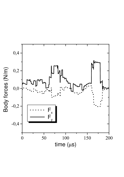
It is found that the calculated space averaged ponderomotive forces per unit volume increases when the electrode width increases Pinheiro_06 . On average, during the second half-cycle the ponderomotive force magnitude decreases with a magnitude of a few Nm as shown in Fig. 9, a result consistent with experimental results as such presented in Ref. Takeuchi . This happens when the voltage polarity is reversed and the energized electrode play the role of cathode. This is due to the potential gradient reduction on the edge of the expanding plasma (see also Ref. 10 ). This numerical result is contrary to experimental study presented in Ref. Hoskinson , showing that the forces decay exponentially with increasing electrode diameter. This is due to the role of the dielectric that in our model was assumed to absorb electric charged particles instead to feed the swarms and strengthening the body forces (see also Ref. Pinheiro_06 ). However, there is still no consensus on the ponderomotive force dependency. For example, Singh and Roy Singh_08 obtained the magnitude of approximated force and have shown that it increases with the fourth power of the amplitude of the rf potential, implying that the induced fluid velocity also increase. This is certainly an aspect that must be dealt with more caution.
In fact, electrons are faster than ions. After the first breakdown, they start to charge negatively the dielectric during the 1 half-cycle; positive ions gains more energy and electrons are also increasingly accelerated, due to a higher growing potential. Therefore, the positive ions density is bigger during this half-cycle, resulting in stronger ponderomotive forces.
During the 2 half-cycle, positive ions (which are mainly formed in volume) tend towards both the electrode and the dielectric surface; the charge surface density on the dielectric start to become less negative and the gas voltage decrease, generating less ions and electrons, resulting in smaller body forces; this is the mechanism of an asymmetric flat panel device.
Otherwise, if the discharge is entirely symmetrical in both half-cycles, it is expected that the average gas speed equals zero. In fact, it is the asymmetry in the streamers (in our case bigger during the fist half-cycle) that gives an overall positive gas speed along the axis.
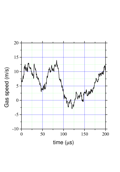
In our present model, calculations of EHD ponderomotive force have shown that its maximum intensity is attained during electron avalanches, with typical values on the order of N/m3. points along OX (propelling direction), while points downwards (boundary layer control). Our calculations show that the resulting average gas speed is about 20 ms and the net EHD body forces (with the present conditions) have comparable values in the first and second-half cycle, although slightly bigger during the first half-cycle, as shown in Fig. 10. It is clear that the successive streamers that charge the dielectric surface are responsible for pulling the flow upstream, unidirectionally, as recent experiments have shown Takeuchi .
IV Conclusion
A two-dimensional fluid model of an asymmetric plasma actuator display the behavior of charged species during both half-cycles when electrodes are subject to a sinusoidal applied voltage. The actuator is strongly dominated by N dynamics, charged species form preferentially at the edge of the electrode with the insulator, and their subsequent behavior and ability to provide an unidirectional gas speed results from the interaction of the charged species with the dielectric, in particular, the effect of the electric field above the insulator and the propensity of the dielectric surface to adsorb or not charged species, and thus controlling the plasma density of the streamers. An appropriate model to describe a realistic interactions of charged species with the dielectric for plasma density enhancement remains to be done, lacking in the literature a more careful study of this important issue.
Acknowledgements.
The authors gratefully acknowledge partial financial support by the Reitoria da Universidade Técnica de Lisboa and the Fundação Calouste Gulbenkian. We would also like to thank important financial support to one of the authors (A.A.M,) in the form of a PhD Scholarship from FCT (Fundação para a Ciência e a Tecnologia).References
- (1) El-Khabiry S. and Colver G. M. 1997 Drag reduction by dc corona discharge along an electrically conductive flat plate for small Reynolds number flow Phys. Fluids 9(3) 587-599
- (2) Roth J. R. 2003 Aerodynamic flow acceleration using paraelectric and peristaltic electrohydrodynamic effects of a One Atmosphere Uniform Glow Discharge Plasma Phys. Plasmas 10 (5) 2117-2126
- (3) Pinheiro M. J. 2006 EHD Ponderomotive Forces and Aerodynamic Flow Control Using Plasma Actuators Plasma Process. Polym. 3 135-141
- (4) Moreau E. 2007 Airflow control by non-thermal plasma actuators J. Phys. D: Appl. Phys. 40 (3) 605-636
- (5) Soldati A. and Banerjee S. 1998 Turbulence modification by large-scale organized electrohydrodynamic flows Alfredo Phys. Fluids 10 (7) 1742-1756
- (6) Fulgosi M., Soldati A. and Banerjee S. 1999 Turbulence Modulation by an Array of Large-Scale Streamwise Structures of EHD Origin Proc. of FEDSM’99 3rd ASME/JSME Joint Fluids Engineering Conference (San Francisco, CA, July 1999) FEDSM99-6934
- (7) Roth J. R., Madhan R. C. M., Yadav M., Rahel J., and Wilkinson S. P. 2004 Flow Field Measurements of Paraelectric, Peristaltic and Combined Plasma Actuators Based on the One Atmospheric Uniform Glow Discharge Plasma (OAUGDPTM) Proc. 42nd Aerospace Sciences Meeting and Exhibit (Reno, NV) AIAA Paper 2004 - 0845
- (8) Post M. L. and Corke T. C. 2003 Separation Control on High-Angle-of-Attack Airfoil Using Plasma Actuators AIAA Press (Washington, DC) AIAA Paper 2003-1024
- (9) Menier E., Leger L., Depussay E., Lago V. and Artana G. 2007 Effect of a dc discharge on the supersonic rarefied air flow over a flat plate J. Phys. D: Appl. Phys. 40 695-701
- (10) Popovic S. and Vuskovic L. 2006 Aerodynamic effects in weakly ionized gas: phenomenology and applications in The Physics of Ionized Gases AIP Conference Proceeindings 876 272-283
- (11) David Sigelman 1970 Sonic boom minimization schemes J. Aircraft 7 (3) 280
- (12) Cain T., Boyd D. 1999 Electroaerodynamics and the Effect of an Electric Discharge on Cone/Cylinder Drag at Mach 5 37th Aerospace Sciences Meeting and Exhibit (Reno, NV) AIAA-99-0602
- (13) Huang X., Chan S. and Zhang X. 2007 Atmospheric plasma actuators for aeroacoustic applications IEEE Trans. Plasma Sci. 35 (3) 693-695
- (14) Chan S., Zhang X. and Gabriel S. 2005 The Attenuation of Cavity Tones Using Plasma Actuators 11th AIAA/CEAS Aeroacoustics Conference 26th AIAA Aeroacoustics Conference (Monterey, CA) AIAA Paper 2005-2802
- (15) J. R. Roth 1999 “Method and apparatus for cleaning surfaces with a glow discharge plasma at one atmosphere of pressure”, US Patent 5,938,854
- (16) Shin J., Narayanaswamy V., Laxminarayan V., Raja L. and Clemens N. T. 2007 Characterization of a Direct-Current Glow Discharge Plasma Actuator in Low-Pressure Supersonic Flow AIAA Journal 45 (7) 1596-1605
- (17) Utkin Y. G., Keshav S., Kim J.-H., Kastner J., Adamovich I. G. and Samimy Mo 2007 Development and use of localized arc filament plasma actuators for high-speed flow control J. Phys. D: Appl. Phys. 40 685-694
- (18) Font G. I. 2004 Boundary Layer Control with Atmospheric Plasma Discharge 40th AIAA/ASME/SAE/ASEE Joint Propulsion Conference and Exhibit (Fort Lauderdale, Fl) AIAA Paper 2004-3574
- (19) Font G. I. and Morgan W. L. 2005 Plasma Discharges in Atmospheric Pressure Oxygen for Boundary Layer Separation Control 35th AIAA Fluid Dynamics Conference and Exhibit (Toronto, Ontario) AIAA Paper 2005-4632
- (20) Font G. I., Jung S., Enloe C. L., McLaughlin T. E., Morgan W. L. and Baughn J. W. 2006 Simulation of the effects of force and heat produced by a plasma actuator on neutral flow evolution 44th AIAA Aerospace Sciences Meeting and Exhibit (Reno, NV) AIAA Paper 2006-0167
- (21) J. P. Boeuf, Y. Lagmich, Th. Unfer, Th. Callegari, and L. C. Pitchford 2007 Electrohydrodynamic force in dielectric barrier discharge plasma actuator J. Phys. D: Appl. Phys. 40 (3) 652-662
- (22) J. P. Boeuf, and L. C. Pitchford 2005 Electrohydrodynamic force and aerodynamic flow acceleration in surface dielectric barrier discharge J. Appl. Phys. 97 103307
- (23) Göksel B., Greenblatt D., Rechenberg I., Singh Y., Nayeri C. N. and Paschereit C. O. 2006 Pulsed plasma actuators for separation flow control Conference on Turbulence and Interactions TI2006 (Porquerolles, France)
- (24) Enloe C L, McLaughlin T E, VanDyken R D, Kachner K D, Jumper E J and Corke T C 2003 Mechanisms and responses of a single dielectric barrier plasma AIAA 2003-1021
- (25) Font G I, Jung S, Enloe C L, McLaughlin T E, Morgan W L and Baughn J W 2006 Simulation of the Effects of Force and Heat Produced by a Plasma Actuator on Neutral Flow Evolution AIAA 2006-0167
- (26) Singh K P, Subrata R and Gaitonde D V 2006 Modeling of Dielectric Barrier Discharge Plasma Actuator with Atmospheric Air Chemistry AIAA 2006-3381
- (27) Gadri R B 1999 One atmosphere glow discharge structure revealed by computer modelingIEEE Trans. Plasma Sci. 27 36-37
- (28) Kossyi I A, Kostinsky A Y, Matveyev A A, and Silakov V P 1992 Kinetic scheme of the non-equilibrium discharge in nitrogen-oxygen mixtures Plasma Sources Sci. Technol. 1 207-220
- (29) Ferreira C M, Alves L L, Pinheiro M and Sá P A 1991 Modeling of Low-Pressure Microwave Discharges in Ar, He and O2: Similarity Laws for the maintenance field and mean powertransferIEEE Trans. Plasma Sci. 19 229-239
- (30) Siglo Data Base: http:cpat.ups-tlse.fr
- (31) Sigmond R S 1979 Gas Discharge Data Sets for Dry Oxygen and Air Electron and Ion Physics Research Group Report The Norwegian Institute of Technology, The University of Trondheim
- (32) Gouda G and Massines F 1999 Role of excited species in dielectric barrier discharge mechanisms observed in helium at atmospheric pressureElectrical Insulation and Dielectric Phenomena Annual Report Conference 2 496-499
- (33) Patankar S V 1980 Numerical heat transfer and fluid flow, (New York: Taylor Francis)
- (34) Morrow R and Sato N 1999 The discharge current induced by the motion of charged particles in time-dependent electric fields; Sato’s equation extended J. Phys. D: Appl. Phys. 32 L20-L22
- (35) Gibalov V I and Pietsch G J 2004 Properties of dielectric barrier discharges in extended coplanar electrode systems J. Phys. D: Appl. Phys. 37 (15) 2093-2100
- (36) Rickard M, Dunn-Rankin D, Weinberg F and Carleton F 2006 Maximizing ion-driven gas flows J. Electrostat. 64 (6) 368-376
- (37) Shvydky A, Nagorny V P and Khudik V N 2004 The electron avalanche sliding along the dielectric surfaceJ. Phys. D: Appl. Phys. 37 2996-2999
- (38) Ráhel J and Sherman D M 2005 The transition from a filamentary dielectric barrier discharge to a diffuse barrier discharge in air at atmospheric pressure J. Phys. D: Appl. Phys. 38 (4) 547-554
- (39) Massines F, Rabehi A, Decomps Ph, Gadri R B, Segur P and Mayoux Ch 1998 Mechanisms of a Glow Discharge at Atmospheric Pressure Controlled by Dielectric BarrierJ. Appl. Phys. 83 (6) 2950-2957
- (40) Boeuf J P and Pitchford L C 1995 Field reversal in the negative glow of a dc glow dischargeJ. Phys. D: Appl. Phys.28 2083-2088
- (41) Kolobov V I and Tsendin L D 1992 Analytic model of the cathode region of a short glow discharge in light gases Phys. Rev. A 46 (12) 7837-7852
- (42) Pinheiro M J 2004 Phys. Rev. E 70 056409; Pinheiro M J 2007 Gas Discharges-Fundamentals and applications, ed. Jayr de Amorim Filho, Transworld Research Network, Kerala, India
- (43) Boeuf J P and Pitchford L C 2005 Electrohydrodynamic force and aerodynamic flow acceleration in surface dielectric barrier dischargesJ. Appl. Phys. 97 (10) 103307-103307-10
- (44) Roth J R 2001 Industrial Plasma Engineering, 2, 235 (IOP, Bristol)
- (45) Takeuchi N, Yasuoka K and Ishii S 2007 Measurement of instantaneous Gas Flow Induced by Plasma Actuator with Laser Doppler Velocimeter Proc. 18th International Symposium on Plasma Chemistry 29C-a5 645 Kyoto, Ed. K. Tachibana, O. Takai, K. Ono, T. Shirafuji
- (46) Hoskinson A R, Hershkowitz N and Ashpis D E 2008 Force measurements of single and double barrier DBD plasma actuators in quiescent air J. Phys.D: Appl. Phys. 41 (24) 245209-245209-9
- (47) Singh K P and Subrata R 2008 Force approximation for a plasma actuator operating in atmospheric airJ. Appl. Phys. 103 013305-013305-6