Quantum fluctuation and geometrical frustration effects on electric polarization
Abstract
We examine theoretically a possibility of ferroelectricity caused by electronic charge order without inversion symmetry, motivated by layered iron oxides. Quantum electronic models in a paired-triangular lattice are analyzed by utilizing the variational Monte Carlo simulation. Our calculation demonstrates that combined effects of electron transfer between the layers, corresponding to quantum fluctuation between the potential minima, and geometrical frustration promote appearance of an electric polarization. Present results are in contrast to the conventional manner of quantum fluctuation in ferroelectricity.
pacs:
77.80.-e, 71.10.-w, 75.80.+qIn solid state textbook, it has been explained that ferroelectric transition in the displacive-type ferroelectricity is caused by a balance of the long-range Coulomb interaction and the short-range repulsion between ions. In addition to these classical explanation, recently developed ab-initio band calculations reveal that the electron covalency between cations and anions have considerable contributions in the ferroelectric transition. As for the order-disorder type ferroelectricity, the classical dipole-dipole interaction aligns the permanent dipoles and brings about the ferroelectric transition. Quantum effect plays important roles on the hydrogen-bond type ferroelectricity Blinc ; deGennes . The quantum proton tunneling between the two potential minima suppresses the transition, and arouses the quantum phase transition between the ferroelectric and quantum paraelectric phases.
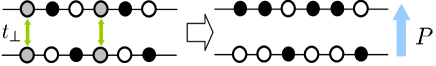
There is another class of ferroelectricity where an electric dipole and a ferroelectric transition are attributed to the electronic origin. This is termed an electronic ferroelectricty. For this type of the ferroelectricity, several experiments in transition-metal oxides Kato ; Ikeda ; Tokunaga and organic salts Monceau ; Yamamoto ; horiuchi have been reported, and some exotic theoretical ideas have been proposed Efremov ; Brink . Most of the systems belong to the charge-ordered insulator with the so-called 1/4 filling, and a charge alignment without the inversion symmetry is responsible for the electric dipole moments. Here we give a simple example in Fig. 1; a charge order (CO) model in a pair of chains or layers. In the CO with the three-fold or odd-fold periodicity, a pair of the charge-neutral sites, represented by the grey circles, is sandwiched between the checker-board type charge configuration. Quantum charge fluctuations are caused by the electron transfer between the two potential minima. When the electrons are localized in one side due to some cooperative interactions, the macroscopic electric dipole appears.
Instead of extensive material syntheses and experimental examinations in the electronic ferroelectricity, the microscopic mechanisms have not been clarified yet. The long-range Coulomb interaction may promote an electronic charge ordering associated with electric polarization. In comparison with other types of ferroelectricity, quantum fluctuation due to electron motion should be crucially important, because the electron mass is much smaller than the proton and ion masses. Large fluctuation causes the diffusive nature in the dielectric constant and the optical spectra observed commonly in this class of material Ikeda ; Monceau ; Xu . It is expected naively that such fluctuation prevents a system from the long-range dielectric order, on the analogy of the quantum phase transitions in the hydrogen-bond type ferroelectricity and SrTiO3.
In this Letter, we demonstrate, against such conventional expectation, that, in a frustrated geometry, a quantum charge fluctuation promotes the electric polarization. The present study is motivated by an electronic ferroelectric material, the layered iron oxide Fe2O4 (=Lu, Yb, Y). The crystal structure is made up of a stacking of the paired-triangle lattices Kimizuka , as shown in Fig. 4(a). The nominal valence of a Fe ion is 2.5+ implying a coexisting of an equal amount of Fe2+ and Fe3+. The electric polarization measured by the pyroelectric current is enhanced around the charge ordering temperature of the three-fold Ikeda ; Yamada ; Mulders . A charge disproportionation in the paired-triangle layers is believed to be responsible for the electric dipole moment, as expected in Fig. 1. Here we concentrate on a paired-triangle lattice, and take up a possibility of the electronic ferroelectricity. In particular, as well as the quantum charge fluctuation, we focus on roles of the geometrical frustration which is often seen in the electronic ferroelectric materials Kato ; Ikeda ; Yamamoto . To explore this issue, the three electronic models are analyzed by the numerical method of the variational Monte-Carlo (VMC) simulation. We show that the electron transfer between the layers, corresponding to the quantum fluctuation between the potential minima, stabilizes the electric polarization, when the system is strongly frustrated.
We start from a possibility of the electronic ferroelectricity in a simple spin-less fermion model where the long-range Coulomb interactions and the electron transfers are taken into account. We consider a pair of the triangular layers where two triangular lattices are regularly stacked along the axis as shown in Fig. 2(a); a site in the upper layer is just upon a site in the lower one. Effects of the realistic crystal structure of Fe2O4 and spin degree of freedom will be considered later. The Hamiltonian is given as with
| (1) | |||||
and
| (2) | |||||
where is the creation operator for a spin-less fermion at site on the upper layer or the lower one , and is the number operator. A subscript takes a two-dimensional coordinate in a triangle lattice. To examine roles of frustration, we consider an anisotropic triangular lattice where bonds along the [110] direction are inequivalent to those along [100] and [010] [see Fig. 2(a)]. Introduced , and are the Coulomb interactions between the nearest-neighboring (NN) sites along the [100] and [010] directions, the [110] one, and the [001] one, respectively. Symbols and imply summations for the NN pairs. The three transfer integrals, , and , are defined in the same way. Ratios and express measure of frustration.
Our optimization VMC method can perform unbiased calculation where both the frustration and quantum effects are treated accurately Umrigar . We adopt 2-5105 samples in most of the simulations where an error of the energy expectation value is of the order of . Systems used are of sites with the periodic- and antiperiodic-boundary conditions, and the particle number is . A variational wave function is defined as , with the one-body Hartree-Fock (HF) part and the many-body correlation factor . We define where takes one of the three variational parameters, , and , when the NN pairs are along the [100] and [010] directions, the [110] one and the [001] one, respectively. As for , we assume the HF wave functions for the following four-types of the CO structures; (i) a two-fold CO along the [110] direction termed CO1/2-I, (ii) a two-fold CO along [100] termed CO1/2-II, (iii) a four-fold CO along [110] termed CO1/4, and (iv) a three-fold CO along [110] termed CO1/3 [see Fig. 2(a) and the inset of Fig. 2(b)]. In each CO, a magnitude of the order parameter is introduced as a variational parameter in . In the CO1/2-I, CO1/2-II and CO1/4 structures, stackings of the CO patterns in the two triangular-layers are set to be out-of-phase. In CO1/3, the assumed pattern along the direction is schematically () in the upper (lower) plane. Symbols , and imply the charge densities of , and zero, respectively.
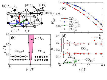
In Fig. 2(a), we present the CO phase diagram. We set up and , and focus on roles of the frustration, , and the electron transfer. In the classical limit, i.e. , the CO1/2-I (CO1/4) structure are realized in the regions of (). The CO1/2-II structure is degenerate with CO1/4. The CO1/3 structure of the present interest appears only at where all CO’s are degenerate. By introducing , CO1/3 appears in a finite parameter region. That is, CO1/3 is stabilized by a combined effect of the quantum fluctuation and the geometrical frustration.
The energy expectation is presented as a function of at in Fig. 2(c). It is clearly shown that a stabilization of CO1/3 is attributed to the -linear dependence of , in contrast to the quadratic dependence in other CO’s. A schematic pattern of CO1/3 is shown in Fig. 2(a). The energy gain is caused by the inter-layer electron transfer, as follows. Let us focus on a pair of the gray circles in the upper and lower layers in Fig. 2(a). This system corresponds to the symmetric double-wells aligned on a triangle lattice. Since these sites are surrounded by the in-plane three NN charge-rich and three poor sites, the Coulomb interactions are canceled out. Thus, the classical energy does not depend on the charge configurations at the sites represented by the gray circles in Fig. 2(a). This degeneracy of the order of is lifted independently at each site by the first order of . Even when the longer-range Coulomb interactions than , and are considered, this scenario survives in the case where is larger than those interactions.
The electric-polarization correlation defined by with is presented in Fig. 2(d). The possible maximum value of in CO1/3 is one. The obtained value in CO1/3 is much higher than those in other CO’s. However, with increasing the system size , a magnitude of in CO1/3 decreases considerably. We suppose that amplitude of in the thermodynamic limit is much smaller than its maximum value.
The above results imply that the quantum charge fluctuation and the geometrical frustration promote the three-fold CO upon which the electric polarization has a chance to appear. However, in the large system size, the amplitude of in the polar state is rather small. When we focus on one of the paired-grey sites in Fig. 2(a), corresponding to a symmetric double-well potential, the bonding state is stabilized by , and a symmetric charge distribution is realized. The present numerical results imply that, within this model, the effective interactions between the pairs are not enough to induce an asymmetric charge distribution. We expect that additional small factors, which are not taken into account so far, may stabilize the polar CO structure. We propose two plausible candidates, the spin degree of freedom and the realistic crystal structure in Fe2O4.
We are modeling the spin degree of freedom on the basis of LuFe2O4 where two kind spins, in Fe2+ and in Fe3+, coexist. An excess electron in a Fe2+ is itinerant and is responsible for CO, and others are regarded as a localized spin with because of their small transfer integral Nagano ; Naka . The model is made up of the itinerant electrons coupled ferromagnetically with the localized spins through the on-site Hund coupling. This is a kind of the double-exchange model. We assume, for simplicity, the infinite-limit of the Hund coupling and the Ising-type localized spins denoted by which takes . The Hamiltonian is where is given in Eq. (2). The first term is the same form with Eq. (1), but the all transfer integrals are replaced by the spin dependent forms. For example, where for and zero for . The last term is the antiferromagnetic interaction between the localized spins, with the positive exchange constant . We analyze this model by using the VMC method. We consider all possible magnetic orders in the localized-spin sector characterized by the momenta which corresponds to the observed neutron diffraction peak at in LuFe2O4 Akimitsu ; Shiratori ; Angst ; Wu . We restrict our calculations to the most frustrated case, i.e. and .
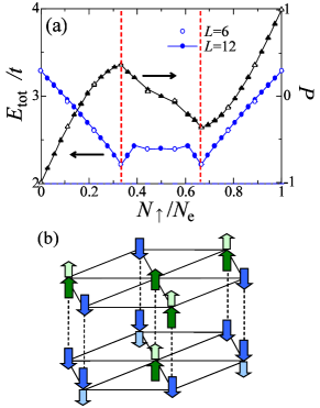
In Fig. 3(a), the energy and the polarization correlation in the optimized spin state are plotted as a function of . Here, is the number of the conduction electrons with spin up (down) and . The energy minima are seen at and (), where a large value of () is realized. A magnitude of is almost independence of the system size. That is, the polar state becomes robust by the spin ordering.
This stabilization of the polar state is attributed to the so-called gate effect due to spin degree of freedom as follows. The optimized spin structure is presented in Fig. 3(b). It is easily seen that, without the spin degree of freedom, the classical energy is not changed by an electron motion from a site in the lower layer to the one just upon it. The energy gain in this process is proportional to , being similar to the previous situation in the CO1/3. In contrast to the previous case, the spin order suppresses the electron hopping, and keeps the electrons in the lower layer. This effect is seen, for example, for the down-spin electrons in the lower layer; since the number of the down localized-spins in the lower layer is twice of that in the upper one, the down-spin electrons are confined in the lower layer to gain the in-plane kinetic energy. In other word, the itinerant electrons are magnetically polarized by the localized spins. As a result, charge imbalance is induced between the layers, and the electric polarization appears. It is worth noting that the spontaneous spin- and charge-polarizations in the conduction electrons are not caused by an asymmetric potential due to the localized spins; the optimized localized-spin configuration is invariant under the space and time inversions plus the in-plane translation along [100].
Another candidate to realize the polar CO state is the realistic crystal structure in Fe2O4. Unlike in the models considered so far, in Fe2O4, a position of a Fe ion in the upper layer is not just upon a Fe ion in the lower layer, but is upon an O ion surrounded by three in-plane Fe ions [see Fig. 4(a)]. We modify the previous Hamiltonian by considering this crystal structure. We introduce the long-range Coulomb interactions for the in-plane NN sites (), that for the inter-plane NN ones (), and for the inter-plane NNN ones (). When the -type Coulomb interaction is assumed, we have and Kimizuka . As for the electron transfer term , the transfer integral for the in-plane NN sites (), and that for the inter-plane NN ones () are introduced. This model is analyzed by the VMC method. Instead of the CO1/3 introduced previously, we adopt the polar three-fold CO (polar CO1/3) and the six-fold one (CO1/6) which are degenerate in the HF level. The CO patterns along is schematically ( ) in the upper (lower) plane for the polar CO1/3, and is ( ) for CO1/6, which is regarded as an antiferro-electric state. Symbols and imply the charge densities of and , respectively, with the variational parameter .
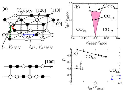
The phase diagram is shown in Fig. 4(b) in a plane of and . Relations and are assumed, although the qualitative features introduced below are robust around these relations. In the classical limit of , is the fully frustrated point, where the polar CO1/3 is degenerate with other CO’s. This is similar to the results in Fig. 2(b). By taking the electron transfer into account, the polar CO1/3 appears around this point. Beyond , the non-polar CO1/6 overcomes the polar CO1/3. The electric polarization presented in Fig. 4(c) shows almost the maximum value in the polar CO1/3, and its value is independence of the system size . On the other hand, a value of in CO1/6 tends to vanish in the thermodynamic limit.
Key interactions to stabilize the polar CO1/3 are the inter-layer charge transfer, , and the long-range Coulomb interaction, , which is not disregarded in this crystal structure. As shown in Fig. 4(a), induces the interaction along the [120] direction between the bonds which are represented by the pairs of the black-white circles connected by the grey bars. These bonds correspond to the pairs of the grey circles in Fig. 2(a). As a result, asymmetric charge distributions in the bonds overcome the symmetric ones in the bonding states which are realized in the previous model of . Although the dipole moments are induced in the local bonds, there is still competition between the polar CO1/3 and the antiferro-electric CO1/6 which are in the different configurations of the dipole moments along [100]. This degeneracy is lifted by . Consider the charge fluctuation at the sites represented by the black (white) circles in the upper (lower) layer in Fig. 4(a). In the inter-layer charge fluctuation by , the energy reduction is of the order of where the intermediate-state energy is the smallest Coulomb interaction in the present model of . Therefore, this kind fluctuation easily occurs and stabilizes the polar CO1/3. In other CO’s, this fluctuation process is suppressed or prohibited.
Through the present analyses, of the three-type models in a paired-triangular lattice we demonstrate that the quantum charge fluctuation due to the electron transfer promotes the electric polarization. In particular, the polar phase is stabilized remarkably due to the inter-layer charge fluctuation in the strongly frustrated condition. The spin degree of freedom of electron and the realistic crystal structure in Fe2O4 are also the key ingredients for the electric polarization. In comparison with the hydrogen-bond type ferroelectricity where the proton tunneling suppresses the long-range order, the charge fluctuation in the present electronic ferroelectricity plays a distinguish role. From the present scenario of the ferroelectricity driven by the quantum fluctuation, the experimentally observed diffusive dielectric constant Ikeda and the valence fluctuation suggested by the optical and Mssbauer measurements Xu ; Nakamura are naturally understood. Here, a classical picture, i.e. the polar charge order stabilized by the Coulomb interaction, is not applicable, and a fragile electric polarization is of prime essence. The present results open a new aspect of the quantum fluctuation in ferroelectricity.
Authors would like to thank S. Mori, N. Ikeda H. Takashima and J. Nasu for their valuable discussions. This work was supported by JSPS KAKENHI, TOKUTEI from MEXT, and Grand challenges in next-generation integrated nanoscience.
References
- (1) R. Blinc et al., J. Phys. Chem. Solids 13, 204 (1960).
- (2) P. G. de Gennes et al., Sol. St. Comm. 1, 132 (1963).
- (3) K. Kato, and S. Iida J. Phys. Soc. Jpn. 51, 1335 (1982).
- (4) N. Ikeda et al., Nature 436, 1136 (2005), and N. Ikeda et al., J. Phys. Soc. Jpn. 69, 1526 (2000).
- (5) Y. Tokunaga et al., Nature Mat. 5, 937 (2006).
- (6) P. Monceau, et al., Phys. Rev. Lett. 86, 4080 (2001).
- (7) K. Yamamoto et al., J. Phys. Soc. Jpn. 77, 074709 (2008).
- (8) S. Horiuchi and Y. Tokura, Nature Mat. 7, 375 (2008).
- (9) D. V. Efremov et al., Nature Mat. 3, 853 (2004).
- (10) J. van den Brink, and D. I. Kohmskii, arXiv:0803.2964.
- (11) X. S. Xu et al., Phys. Rev. Lett. 101, 227602 (2008).
- (12) N. Kimizuka et al., in Handbook on the Physics and Chemistry of Rare Earth edited by K. A. Gshneider Jr. and L. Eyring, 13, 283 (Elsevier, 1990).
- (13) Y. Yamada et al., J. Phys. Soc. Jpn. 66, 3733 (1997).
- (14) A. M. Mulders et al., arXiv:0812.3094.
- (15) C. J. Umrigar et al., Phys. Rev. Lett. 60, 1719 (1988).
- (16) J. Akimitsu et al., Sol. St. Comm. 32, 1065 (1979).
- (17) K. Shiratori et al., Proceedings of the 6th international conference of Ferrites, 703 (1992).
- (18) M. Angst et al., Phys. Rev. Lett. 101, 227601 (2008).
- (19) W. Wu, et al., Phys. Rev. Lett. 101, 137203 (2008).
- (20) A. Nagano et al., Phys. Rev. Lett. 99, 217202 (2007).
- (21) M. Naka et al., Phys. Rev. B 77, 224441 (2008).
- (22) S. Nakamura et al., J. Alloys Com. 275-277, 574 (1998).
∗ Present address: Chiba Institute of Technology, Tsudanuma, Chiba 275-0016, Japan.