Fronts of spin tunneling in molecular magnets
Abstract
Dissipative spin-tunneling transitions at biased resonances in molecular magnets such as Mn12 Ac are controlled by the dipolar field that can bring the system on and off resonance. It is shown that this leads to spin relaxation in form of propagating fronts of tunneling, with the dipolar field adjusting self-consistently to provide a zero bias within the front core. There are two regimes of the front propagation: laminar and non-laminar with discontinuous magnetization and dipolar field. In the laminar regime the speed of the front can exceed that of the magnetic deflagration, if the transverse field is large enough. Fronts of tunneling can be initiated by magnetic field sweep near the end of the crystal.
pacs:
75.50.Xx,75.45.+j,76.20.+qI Introduction
Molecular magnets (MM), including their first and mostly studued representative Mn12 Ac, Lis (1980) have initially attracted attention as molecules with the effective big spin showing bistability as a result of a strong uniaxial anisotropy R. Sessoli and Novak (1993) Resonance spin tunneling manifested in the magnetic hysteresis loopsFriedman et al. (1996); Hernández et al. (1996); Thomas et al. (1996) with steps at the field values , made molecular magnets a hotspot of research during more than 10 years.
Crystals of molecular magnets do not show a significant exchange interaction because the magnetic core of the molecule is screened by organic ligands. Thus magnetic molecules remain largely superparamagnetic, although MM can order below 1 K due to dipole-dipole interactions (DDI). Morello et al. (2003); Garanin and Chudnovsky (2008)
An important role of the DDI is that the dipolar field created by the spins is large enough to change the resonance condition for the up and down spins and thus to strongly influence spin tunneling. Fully ordered spins in an elongated Mn12 Ac crystal create the dipolar field mT at a molecule. Garanin and Chudnovsky (2008); S. McHugh, R. Jaafar, M. P. Sarachik, Y. Myasoedov, H. Shtrikman, E. Zeldov, R. Bagai, and G. Christou (2009) This becomes comparable with the resonance width defined by the tunnel splitting in transverse magnetic fields above 5 T, for the tunneling resonance. For smaller transverse fields, is much smaller and thus the DDI can completely block the resonant tunneling. The action of the dipolar field is dynamical and self-consistent since tunneling of spins causes the dipolar field to change, blocking or allowing resonant transitions.
The role of the DDI in spin tunneling was recognized in Refs. Prokof’ev and Stamp, 1998; A. Cuccoli, A. Fort, A. Rettori, E. Adam, and J. Villain, 1999; Alonso and Fernández, 2001; Fernández and Alonso, 2003; P. C. E. Stamp and I. S. Tupitsyn, 2004; I. S. Tupitsyn, P. C. E. Stamp, and N. V. Prokof’ev, 2004; Fernández and Alonso, 2004, 2005 where Monte Carlo simulations were done on the basis of a phenomenological model involving discrete jumps of the spins through the instantaneous “tunneling window”. The main purpose of these studies was to explain the relaxation experimentally observed in Mn12 Ac. W. Wernsdorfer, T. Ohm, C. Sangregorio, R. Sessoli, D. Mailly, and C. Paulsen (1999)
It was not understood until recently that DDI in molecular magnets can result in spatially-inhomogeneous states creating the dipolar field such that the system is on resonance in some regions of space where spins can relax, leading to moving fronts. An example is the domain wall in elongated dipolar-ordered crystals of Mn12 Ac at low temperatures. The reduced dipolar field at in Fig. 2 of Ref. Garanin and Chudnovsky, 2008 is close to zero in the region around the center of the domain wall with the width of the order of the crystal’s thickness. It should be mentioned that Mn12 Ac remains the only molecular magnet that can be grown in long crystals required for such kind of phenomena.
Similar effects can take place in the tunneling at biased resonances, If the external field approaches the resonance by a slow sweep, as was the case in many experiments, moving walls of tunneling can be created near the ends of long crystals (where the dipolar bias is smaller) and then penetrate into their depth with a speed unrelated to the sweep rate. Garanin and Chudnovsky (2009) The role of the sweep is only to create an initial state for the wall of tunneling to start. It was argued that this mechanism can explain the width of the steps in dynamic hysteresis curvesFriedman et al. (1996); Hernández et al. (1996); Thomas et al. (1996) by the time needed for the wall of tunneling to cross the crystal. Non-uniformity of the magnetization in Mn12 Ac developing during spin tunneling was detected by local measurements earlier.Nurit Avraham, Ady Stern, Yoko Suzuki, K. M. Mertes, M. P. Sarachik, E. Zeldov, Y. Myasoedov, H. Shtrikman,1 E. M. Rumberger, D. N. Hendrickson, N. E. Chakov, and G. Christou (2005)
The walls or self-organized patterns of spin tunneling investigated in Ref. Garanin and Chudnovsky, 2009 are not exactly fronts because they are lacking the combined space-time dependence on the argument only, where is the speed of the front. Frozen-in quasiperiodic spatial structures have been found behind these moving walls. In fact, true smooth fronts of spin tunneling do exist in the range of the external bias smaller than that in Ref. Garanin and Chudnovsky, 2009. Studying these fronts and their transition to the moving walls with a nonuniformity behind with increasing the bias is the purpose of this article. It will be shown that there are two regimes.
For the external bias not exceeding a critical value, the true fronts (that can be called “laminar”) are realized in which the dipolar field adjusts to create a resonance in the front region. In the limit of strong dipolar field (relative to the resonance width) the front speed and the magnetization behind the front can be calculated analytically and are independent of the strength of the DDI.
For a larger external bias, the magnetization distribution and thus the dipolar field in the wall cannot fully adjust to provide the resonance condition. In this case the wall is moving with a quasiperiodically varying speed leaving a quasiperiodic state behind. The average wall speed decreases with the DDI strength quadratically.
The dipolar mechanism of spin tunneling is resembling magnetic deflagration in Mn12 Ac. Y. Suzuki, M. P. Sarachik, E. M. Chudnovsky, S. McHugh,R. Gonzalez-Rubio, N. Avraham, Y. Myasoedov, E. Zeldov, H. Shtrikman, N. E. Chakov and G. Christou (2005); Garanin and Chudnovsky (2007) Here, instead of the temperature, the relaxation rate is controlled by the self-consistent dipolar field bringing the system on or off resonance. Thus, in a sense, one can call the phenomenon studied here cold deflagration. Of course, the heat release in the course of the cold deflagration can give rise to the regular deflagration, especially for high resonances and well thermally isolated crystals. In this case the two kinds of deflagration can compete.
The rest of the article is organized as follows. In Sec. II the dynamics of spin tunneling between the metastable ground state and a resonant excited state on the other side of the barrier is considered. The simplified overdamped equations of motion are obtained in the case of the tunnel splitting frequency smaller than the damping of the excited state It is further argued that in the presence of disorder that spreads resonances one can use overdamped equations in a generalized form also for larger In Sec. III the dipolar field created by a wall of magnetization is calculated for the cylindrical and ribbon geometries. In Sec. IV the full system of cold deflagration equations is written and transformed into dimensionless form. In Sec. V the limit of strong DDI is studied and analytical expressions for the residual magnetization behind the front and the front speed are obtained. Sec. VI provides the results of numerical calculations in both regimes of the wall propagation.
II Spin tunneling and relaxation
We will be using the generic giant-spin model of molecular magnets with the Hamiltonian
| (1) |
where is the uniaxial anosotropy and
| (2) |
is the total magnetic field, including the external and dipolar fields. Suppressed terms in the Hamiltonian can include the biaxial and fourth-order anisotropy that can make a contribution into the tunnel splitting of the resonant spin up- and down states. Since the most interesting situation arises in the case of a large that can only be created by a strong transverse field, the dropped terms will not be needed. For the exact quantum states of are with their energies being The resonance condition between all states on the left side of the barrier ( and on the right side of the barrier () is satisfied for the resonance fields
| (3) |
This resonance condition turns out to be independent of the transverse field.
Application of the transverse field leads to the two effects. First, each state hybridyzes with neighbouring states within the same well forming the state that can be denoted as Physically this corresponds to spin canting in the direction of the transverse field. Second, the states on different sides of the barrier hybridize because of the resonance spin tunneling near Of course, one can speak of the states for not too strong transverse field, so that there still are low-lying states well localized within one of the wells. The states provide a basis for a simplified treatment of spin tunneling and relaxation near resonances that otherwise has to be considered within the density-matrix formalism. Garanin and Chudnovsky (1997); Garanin (2008)
Consider the metastable ground state of a molecular magnet, near a tunneling resonance with an excited state on the right side of the barrier, Fig. 1 of Ref. Garanin and Chudnovsky, 2009. The dynamics of tunneling at low temperatures is described by the subset of the density matrix equation (DME) taking into account only these two levels. The level can decay into lower-lying levels within the same well with rate . Since there are no incoming relaxation processes for the state at low temperatures, the DME can be simplified to the form of the damped Schrödinger equation
| (4) |
Here is the tunnel splitting and is the energy bias between the two levels,
| (5) |
In fact, here one should use the values of and corrected for spin canting. Since is the lowest state in the left well, it cannot decay. The numbers of particles in the states are defined by
| (6) |
etc. The spin polarization in our low-temperature tunneling process is given by As the states with decay faster than their contribution can be neglected. Then for the normalized spin-average variable
| (7) |
one obtains
| (8) |
In the overdamped case the variable in Eq. (4) adiabatically adjusts to the instantaneous value of Setting in the second of these equations one obtains
| (9) |
Inserting it into the first of equations (4) one obtains
| (10) |
With the help of Eq. (6), one obtains the equation for the metastable population in the form
| (11) |
where the subscript has been dropped for transparency and the dissipative tunneling rate is given by Garanin and Chudnovsky (1997)
| (12) |
In the overdamped limit one has so that Eq. (8) simplifies to
| (13) |
The decay rate is mainly due to the relaxation between the adjacent energy levels in the right well, , see Eq. (A9) of Ref. Chudnovsky et al., 2005 or Eq. (294) of Ref. Garanin, 2008. For and thus one has s while reaches a comparable value in the transverse field above 3 T. At higher transverse fields the tunneling dynamics should be underdamped. Resonances with higher have larger splitting and become underdamped in smaller transverse fields.
In the case of underdamped resonances, the rate of dissipative spin tunneling can be described by the integral relaxation time resulting in the effective rateGaranin (2008)
| (14) |
where
| (15) |
One can see that in the underdamped case the width of the Lorentzian becomes of the order of , compared to in the overdamped case. Although Eq. (11) with given by Eq. (14) does not accurately describe the oscillating dynamics of the system in the underdamped case, in particular the Landau-Zener effect, it will be used below as an approximation for the many-body problem with coupling via the dipolar field in both overdamped and underdamped cases. A more rigorous approach based on Eq. (4) requires much more computer time because of fast oscillations. On the other hand, oscillations at tunneling resonances have never been experimentally observed in MM because of the resonance spread as a result of ligand disorder and other factors. For the low-bias resonances such as and thus the contribution of in Eq. (8) can be neglected, thus Eq. (13) will be used in all cases.
III Dipolar field
The dipolar field and ensuing dipolar bias of tunneling resonances in crystals of molecular magnets have been discussed in detailes in Ref. Garanin and Chudnovsky, 2008, so that only a short summary with necessary changes will be provided below.
The component of dipolar field at site (i.e., at a particular magnetic molecule), created by molecular spins polarized along the axis is given by
| (16) |
where is the unit-cell volume and
| (17) |
Inside a uniformly magnetized ellipsoid the dipolar field is uniform and one has where
| (18) |
is the number of magnetic molecules per unit cell and and 1 for a cylinder, sphere, and disc, respectively. depends on the lattice structure. For Mn12 Ac lattice summation yields that results in for a cylinder. Then Eq. (16) yields the dipolar field mT in an elongated sample that was also obtained experimentally.S. McHugh, R. Jaafar, M. P. Sarachik, Y. Myasoedov, H. Shtrikman, E. Zeldov, R. Bagai, and G. Christou (2009)
The dipolar bias in Eq. (5) can be written in the form
| (19) |
where
| (20) |
is the dipolar energy, K for Mn12 Ac. Since the dipolar field depends on the magnetization and its values in an elongated crystal can change between mT and mT, one can conclude that, according to Eq. (5), the resonance condition can be, in principle, satisfied in the dipolar tunneling window around the resonance mT mT. This dipolar window is much smaller than the distance between the two tunneling resonances that is about 0.5 T. Practically, for a negative external bias the relaxation is hindered by the causality: To produce a positive dipolar field that would balance the negative external bias, spins should already be on the right side of the barrier.
For a cylinder of length and radius with the symmetry axis along the easy axis, magnetized with the reduced -field along the symmetry axis has the form
| (21) |
where
| (22) |
for Mn12 Ac. In particular, for a long uniformly polarized cylinder one obtains
| (23) |
At the left end of the long cylinder, one has For Mn12 Ac one obtains , having the sign opposite to that of the field in the depth, . This means that a homogeneously magnetized state in the resonance external field may be unstable with respect to spin tunneling beginning in the vicinity of the ends of the cylinder, as at some point near the end the resonance condition is satisfied. To the contrary, dipolar field in the depth of a uniformly magnetized cylinder provides the dipolar bias that puts the system off resonance and makes the transition rate very small. If the external field is swept in the positive direction towards the resonance, spin tunneling begins near the ends of the crystal and then it propagates inside the crystal as a moving wall of tunneling, as the dipolar field changes self-consistently. Garanin and Chudnovsky (2009)
One can also calculate the dipolar field on the symmetry axis of a slab of length and sides and In the case the results are similar to those for the cylinder above. For a thick slab (a ribbon) with one obtains
| (24) |
that has the kernel less localized than that of Eq. (21).
IV Cold deflagration equations
The phenomenon of cold deflagration is described by a collection of equations (11) for every magnetic molecule in the crystal, with the dipolar field controlling transitions being determined by the instantaneous non-uniform magnetization. As the full three-dimensional problem with a long-range interaction requires too much computer power, here the one-dimensional approximation will be made. The magnetization is considered as a function of the coordinate only, i.e., the deflagration fronts are flat, and the dipolar field is taken along the symmetry axis as in Eq. (21) that will be used below. Of course, the dipolar field away from the symmetry axis is different, that will result in non-flat fronts. However, to avoid complications in demonstrating the basic phenomenon, these effects will be ignored here.
It is convenient to introduce the dimensionless time and coordinate as
| (25) |
where is the resonance relaxation rate following from Eq. (14) with neglected,
| (26) |
Then Eq. (11) becomes
| (27) |
where contains integral dependence on via ,
| (28) |
The dimensionless bias with defined by Eq. (5), has the form
| (29) |
where
| (30) |
and defined by Eq. (21) can be rewritten in the form
| (31) |
where and
For a long sample, one can seek for a solution of Eq. (27) in the form of a moving front depending on the combined argument where is the front speed. In reduced units one has where the relation between the real and reduced front speeds has the form
| (32) |
Eq. (27) for the front becomes
| (33) |
where contains
| (34) |
Eq. (32) makes the dependence of on and obvious. However, there are nontrivial parameters and that enter
For a ribbon one can introduce and replace Eqs. (31) and (34) by the corresponding expressions following from Eq. (24).
V The limit of strong dipolar field
Unless a strong transverse field is applied, the numerical value of of Eq. (28) for Mn12 Ac is large. In particular, in the overdamped limit for In this case one could think that is negligibly small everywhere except for a very close vicinity of the resonance, so that the total relaxation and thus the speed of the front are very small. However, as the numerical solution shows, the system finds the way to relax faster by forming a front region of a width where is small and is of order one. In this extended region resonant tunneling transitions take place. Beyond the front region deviates from zero and becomes negligibly small. As a result, changes practically only within the front core.
Basing on these insights, one can construct a perturbative expansion in powers of and show that the solution and the front speed become independent of for One can search for in the form
| (35) |
and similarly for The term is defined by the condition that within the front region with the width to be determined self-consistently, the contribution of into the bias is zero. If this is fulfilled, the term in the denominator of Eq. (28) is of order one due to the correction so that in the front region is of order one. In the region before the front, one has and Everywhere behind the front, one has final values and that are to be determined. In the front region the condition with Eq. (29) yields the integral equation
| (36) |
where
| (37) |
This equation determines the zero-order profile including and
Eq. (36) can be solved numerically by discretizing the integral using equidistant points within the interval given by The value at the right end of the interval is fixed by the boundary condition Thus there are total unknowns including that can be found by solving the system of equations with Note that this system of equations is nonlinear because of In this way one finds the zero-order magnetization profile in the front and the magnetization behind the front for any In particular, for Mn12 Ac one obtains
On the other hand, one can find important analytical results if one searches for the solution in the form
| (38) |
where Substituting this into Eq. (37) one obtains the equation for
| (39) |
where One can see that there are even and odd terms in in this equation and is odd. The even and odd parts of this equation should turn to zero independently of each other. For the even part one obtains the equation
| (40) |
that with yields and
| (41) |
for the fraction of metastable molecules behind the front. Note that since this solution only exists for
| (42) |
The odd part of Eq. (39) yields the equation
| (43) | |||||
that defines and They can be found numerically by discretization as described above. The expression for in terms of following from Eq. (38) has the form
| (44) |
Using the method of Ref. Garanin and Chudnovsky, 2008, one can show that the approximate solution for valid for has the form
| (45) |
where
| (46) |
For a Mn12 Ac cylinder one obtains


Numerically found and its approximation for a Mn12 Ac cylinder is shown in Fig. 3 together with for a thick slab (ribbon) discussed at the end of this section.
The speed of the front can be found by considering the effect of the correction , although one does not need to evaluate this correction explicitly. In Eq. (33) one has to keep in because otherwise the denominator turns to zero. This makes zero order in On the other hand, and outside can be taken at zero order in . One thus can rewrite Eq. (33) in the interval in the form
| (47) |
There is a point inside the interval where changes its sign. At this point reaches its minimal value 1. On the other hand, this point can be determined as the minimum of the rhs of this equation. Then, obviously,
| (48) |
Using Eq. (44) one obtains
| (49) |
One can see that for one has achieved at where This yields at In the general case one has to investigate
| (50) |
Since at
| (51) |
one concludes that for the minimum is achieved at and thus
| (52) |
For a cylinder of Mn12 Ac one has and According to Eq. (49), the latter translates into Then Eq. (30) yields the value of the corresponding bias field mT. For the front speed in real units obtained with the help of Eqs. (30), (16), and (20) is given by
| (53) |
For (and thus one has to find from the condition that leads to somewhat smaller front speeds than given by the formulas above. However, the laminar regime of the cold deflagration fronts breaks down at the external bias smaller than so that the results of this section for are irrelevant.
Let now consider the slab geometry. From Eq. (24) with instead of Eq. (37) one obtains the equation
| (54) |
The numerically obtained result for the normalized magnetization profile is shown of Fig. 3, compared to that of a cylinder. Since the kernel in the integral equation for the slab is less localized for a thick slab than for a cylinder, the front width for a thick slab is larger than for the cylinder. All formulas obtained above are valid for a thick slab as well, however with different constants: , and
VI Numerical results

As mentioned at the end of Sec. IV, the cold-deflagration equations can be solved by discretization reducing them to a system of ordinary differential equation. Numerical calculations use the semi-infinite geometry including the region of length where equations are solved plus the range where the magnetization is fixed to corresponding to the metastable state. The latter is needed to create the dipolar field in the main region that corresponds to the semi-infinite sample. This allows to operate on shorter samples that saves computer time. When the deflagration front reaches it cannot go further, so the results near this point become unphysical and should be ignored.
The first thing revealed by computations is that for large values of it is very important to prepare the system in the initial state close to the actual front, with within the front core. The further is the initial state from this optimal state, the more time (ignition time) the system needs to adjust so the the front could start moving across the sample. For initial states far from the front states, the ignition time can be so long that there is a significant off-resonance relaxation in the bulk of the crystal during it. For smaller dipolar fields such as (that can be achieved by applying a strong transverse field to increase ) ignition of the fronts is much easier. Another possibility to ignite the cold deflagration is to slowly sweep the external field in the positive direction, approaching the resonance, Garanin and Chudnovsky (2009) that will be considered later on.
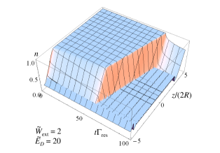
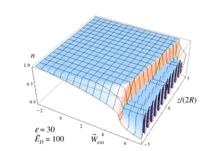
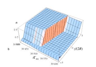
Computations for large and not too strong bias corroborate semi-analytical results of the preceding section. For not too close to the ends of the interval the variables indeed depend on as it should be in a moving front. 3D plots of are smooth and look qualitatively as in Fig. 1, and the ignition time can be reduced to zero by a better choice if the initial state. The metastable population averaged over the length of the crystal is almost flat during the ignition time, then it decreases linearly as the front travels through the crystal, then becomes nearly flat again after the front arrives at the right end of the interval , see Fig. 16 of Ref. Garanin and Chudnovsky, 2007 for the standard magnetic deflagration and Fig. 4 of Ref. Garanin and Chudnovsky, 2009 for the cold deflagration. The front speed can be obtained as
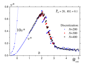
The reduced front speed Eq. (32), vs Eq. (30), is shown for in Fig. 5a. For not too large bias, the numerical results are in a good agreement with Eq. (52) shown by a solid line. In this region the numerical results do not depend on the number of discrete points used in the solution. Similar results for in Fig. 5b are further from the theoretical curve (not shown) because the condition of a strong dipolar field is not fully satisfied. Also there is some nonzero speed in the region that is, however, quickly decreasing with the negative bias.
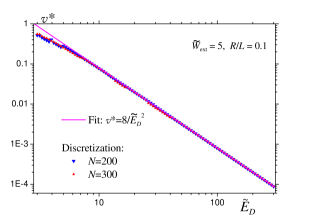
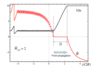
With increasing the external bias, the laminar solution in the form of a smooth moving front loses its stability. In Fig. 2 one can already see wiggles behind the front that represent frozen-in spatial structures with the period of order . With increasing or these features progress and the region of transitions moves with oscillating speed, see Fig. 6. To distinguish this transition region from the true front, it was called “wall of transitions”. Garanin and Chudnovsky (2009) It would cost significant additional efforts to find out analytically or numerically whether the transition from the laminar to non-laminar regime with increasing is gradual or there is a threshold. One important observation is that the spatial structures behind the front are discontinuous on while the analytical result of Eq. (48) was obtained based on the assumption that the solution is continuous.
As the laminar regime breaks down, the instability is manifested by the dependence of the results for in Fig. 5 on the number of discretization points. With increasing the discontinuities in become smaller but, unfortunately, increasing is limited by computing resourses. For larger the front speed reaches a plateau that depends on and curves with different discretizations converge again.
In the non-laminar regime the magnetization in the front cannot completely adjust so that bias in the front core would be very close to zero and the resonance transitions could occur at a rate close to the maximal rate This is the reason why drops after reaching a maximum, as the instability begins. Still the very existence of the front in this case suggests that the system is closer to the resonance in this region than in the others. The values of in the front should be of order 1, so that in Eq. (28) one has This is supported by the computations shown in Fig. 7: In the plateau region (in particular for the front speed fits to
| (55) |
for large
VII Cold deflagration initiated by field sweep
As was mentioned above, for most of initial conditions the development of the cold deflagration front requires a very long ignition time. If the initial condition is chosen in a special way close to the actual front, the process starts immediately. However, one cannot find a practical way to prepare such initial state.
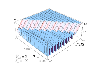
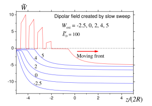
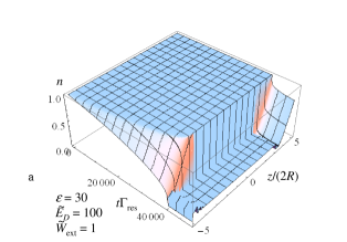
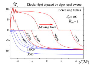
Fortunately, as was found in Ref. Garanin and Chudnovsky, 2009, the front can be ignited by a slow time-linear sweep starting with a value of that ensures everywhere in the sample, see Fig. 8. The sweep rate can be conveniently parametrized by and slow sweep requires As increases, the condition would be first reached at the end of the sample, then the resonance point would move into its depth. However, transitions induced by the sweep (seen in Fig. 8 before the ignition) change the dipolar field so that the system does not cross the resonance in the region near the end of the sample, although it becomes close to the resonance in the increasingly broad region, see Fig. 9. The reason for this is that flipping spins in a small region near the end of the sample do not significantly change the dipolar field from the surface of the crystal, the integral term of Eq. (21), but strongly change the local contribution, last term in this formula. Increasing due to resonance transitions leads to the decrease of the local term that creates a negative dipolar bias and prevents the system from crossing the resonance. After some time the region close to the resonance becomes broad that is similar to the structure of the cold deflagration front, see Fig. 9. In this way the initial state for the cold deflagration is being prepared. The front starts as the bias reaches the “magic” value of that weakly depends on For one has (that corresponds to mT) and for one has At such a strong bias there is a quasiperiodic spatial structure with discontinuous magnetization and the dipolar field behind the front, as shown in Figs. 8 and 9. One can see in Fig. 9 that in the moving front the bias is slightly below zero. This means that the system is somewhat off-resonance and this is the reason for a small front speed in this regime, as shown in Fig. 5.
The next question is how to ignite cold deflagration for arbitrary values of the external bias given by Eq. (30). The answer is to sweep up to this value of and then to stop this (global) sweep at some . After that further sweep locally near the end of the sample, using a small coil. For the coil of radius placed at (the axis of the coil coincides with the axis of the cylinder) the local addition to can be written in the form
| (56) |
with Numerical calculations with and show that, indeed, with this method one can ignite fronts at different biases including the laminar regime, see Fig. 10. Here the front is much faster than in Fig. 8, in accordance with the results for the front speed in Fig. 5a. Total bias in the sample at different times is shown in Fig. 11. For instance, corresponds to the stage of the global sweep. All other times correspond to the local-sweep stage, since the bias curves converge on the right side of the sample where is small. Local sweep near the left end creates an initial state for the front to start, as the bias curves are approaching zero in a progressively large region (blue curves). As the front starts moving (red curves), the bias becomes positive on the left with non-laminar features near the end. But in the depth of the sample the front is laminar corresponding to
VIII Discussion
In the main part of the paper it was shown that elongated crystals of molecular magnets (practically Mn12 Ac) can exhibit moving fronts of dissipative spin tunneling at biased resonances, Eq. (3) with This phenomenon is resembling magnetic deflagration,Y. Suzuki, M. P. Sarachik, E. M. Chudnovsky, S. McHugh,R. Gonzalez-Rubio, N. Avraham, Y. Myasoedov, E. Zeldov, H. Shtrikman, N. E. Chakov and G. Christou (2005); Garanin and Chudnovsky (2007) only the relaxation rate is controlled not by the temperature but by the dipolar field evolving self-consistently and bringing the spins in the front region on and off tunneling resonance. Like deflagration, it leads to destruction of the initial metastable ordered state (however in general incomplete), this is why it can be called “cold deflagration”.
Of course, transitions at biased resonances result in energy release and warming of the sample, so that the two mechanisms can coexist. In fact, magnetic deflagration was observed in crystals of Mn12 Ac thermally isolated so that the warming of the sample is efficient. Without thermal isolation, cold deflagration does not face this competition. To further reduce heating, it is preferable to work at low bias, such as
There are two regimes of cold deflagration: laminar regime at low bias and non-laminar regime at high bias. In the laminar regime the magnetization in the front adjusts so that the dipolar field together with the external field creates a nearly zero bias for the resonance transitions in the front region with the width of order the transverse size of the crystal. In the laminar regime the magnetization and dipolar field in the sample are continuous and both the front speed and the magnetization (metastable population) behind the front can be found analytically in the practical limit of the strong dipolar field, Eqs. (53) and (41). Remarcably, both of these quantities do not depend on the strength of the dipolar field in this region.
In the laminar regime the estimation for the front speed is where is the transition rate at resonance, in Eq. (12). At the boundary between the over- and underdamped regimes, and thus (that is realized in the transverse field T in Mn12 Ac at the resonance) cold deflagration already beats the regular “hot” deflagration. Indeed, the latter has the speed where depends on the thermal diffusivity but experimentally is comparable with and is the thermal activation rate over the barrier at the flame temperature. Since at high temperatures is determined by the rates of transitions between adjacent levels near the top of the barrier that are smaller than the same for low-lying levels such as (one has s-1 and s the hot deflagration loses.
At higher bias the laminar regime breaks down, the dipolar field cannot fully adjust to provide a nearly zero bias in the front’s core, and the magnetization and the dipolar field become discontinuous. There are frozen-in quasiperiodic spatial structures behind the front. Accordingly, the front speed dramatically drops, see Fig. 5, especially in the case of a strong dipolar field. There is no analytical solution in this range but the fit to the numerical results yields The boundary between the laminar and non-laminar regimes corresponds to -10 mT.
It was shown that cold deflagration can be ignited by the local sweep of the field near an end of the crystal. This local field can be produced by a small coil with increasing current.
Another condition for the observability of the cold deflagration is sufficiently strong transverse field that allows tunneling transitions via low-lying levels.
At nonzero temperatures the rate of cold deflagration should increase because of the activation to higher levels providing a higher transition probability, see Eq. (10) of Ref. Garanin and Chudnovsky, 2009.
Acknowledgements
The author is indebted to E. M. Chudnovsky for many stimulating discussions.
This work has been supported by the NSF Grant No. DMR-0703639.
References
- Lis (1980) T. Lis, Acta Crystallogr. B 36, 2042 (1980).
- R. Sessoli and Novak (1993) A. C. R. Sessoli, D. Gatteschi and M. A. Novak, Nature (London) 365, 141 (1993).
- Friedman et al. (1996) J. R. Friedman, M. P. Sarachik, J. Tejada, and R. Ziolo, Phys. Rev. Lett. 76, 3830 (1996).
- Hernández et al. (1996) J. M. Hernández, X. X. Zhang, F. Luis, J. Bartolomé, J. Tejada, and R. Ziolo, Europhys. Lett. 35, 301 (1996).
- Thomas et al. (1996) L. Thomas, F. Lionti, R. Ballou, D. Gatteschi, R. Sessoli, and B. Barbara, Nature 383, 145 (1996).
- Morello et al. (2003) A. Morello, E. L. Mettes, F. Luis, J. F. Fernández, J. Krzystek, G. Aromi, G. Christou, and L. J. de Jongh, Phys. Rev. Lett. 90, 017206 (2003).
- Garanin and Chudnovsky (2008) D. A. Garanin and E. M. Chudnovsky, Phys. Rev. B 78, 174425 (2008).
- S. McHugh, R. Jaafar, M. P. Sarachik, Y. Myasoedov, H. Shtrikman, E. Zeldov, R. Bagai, and G. Christou (2009) S. McHugh, R. Jaafar, M. P. Sarachik, Y. Myasoedov, H. Shtrikman, E. Zeldov, R. Bagai, and G. Christou, Phys. Rev. B 79, 052404 (2009).
- Prokof’ev and Stamp (1998) N. V. Prokof’ev and P. C. E. Stamp, Phys. Rev. Lett. 80, 5794 (1998).
- A. Cuccoli, A. Fort, A. Rettori, E. Adam, and J. Villain (1999) A. Cuccoli, A. Fort, A. Rettori, E. Adam, and J. Villain, Eur. Phys. J. B 12, 39 (1999).
- Alonso and Fernández (2001) J. J. Alonso and J. F. Fernández, Phys. Rev. Lett. 87, 097205 (2001).
- Fernández and Alonso (2003) J. F. Fernández and J. J. Alonso, Phys. Rev. Lett. 91, 047202 (2003).
- P. C. E. Stamp and I. S. Tupitsyn (2004) P. C. E. Stamp and I. S. Tupitsyn, Phys. Rev. B 69, 014401 (2004).
- I. S. Tupitsyn, P. C. E. Stamp, and N. V. Prokof’ev (2004) I. S. Tupitsyn, P. C. E. Stamp, and N. V. Prokof’ev, Phys. Rev. B 69, 132406 (2004).
- Fernández and Alonso (2004) J. F. Fernández and J. J. Alonso, Phys. Rev. B 69, 024411 (2004).
- Fernández and Alonso (2005) J. F. Fernández and J. J. Alonso, Phys. Rev. B 72, 094431 (2005).
- W. Wernsdorfer, T. Ohm, C. Sangregorio, R. Sessoli, D. Mailly, and C. Paulsen (1999) W. Wernsdorfer, T. Ohm, C. Sangregorio, R. Sessoli, D. Mailly, and C. Paulsen, Phys. Rev. Lett. 82, 3903 (1999).
- Garanin and Chudnovsky (2009) D. A. Garanin and E. M. Chudnovsky, Phys. Rev. Lett. 78, 097206 (2009).
- Nurit Avraham, Ady Stern, Yoko Suzuki, K. M. Mertes, M. P. Sarachik, E. Zeldov, Y. Myasoedov, H. Shtrikman,1 E. M. Rumberger, D. N. Hendrickson, N. E. Chakov, and G. Christou (2005) Nurit Avraham, Ady Stern, Yoko Suzuki, K. M. Mertes, M. P. Sarachik, E. Zeldov, Y. Myasoedov, H. Shtrikman,1 E. M. Rumberger, D. N. Hendrickson, N. E. Chakov, and G. Christou, Phys. Rev. B 72, 144428 (2005).
- Y. Suzuki, M. P. Sarachik, E. M. Chudnovsky, S. McHugh,R. Gonzalez-Rubio, N. Avraham, Y. Myasoedov, E. Zeldov, H. Shtrikman, N. E. Chakov and G. Christou (2005) Y. Suzuki, M. P. Sarachik, E. M. Chudnovsky, S. McHugh,R. Gonzalez-Rubio, N. Avraham, Y. Myasoedov, E. Zeldov, H. Shtrikman, N. E. Chakov and G. Christou, Phys. Rev. Lett. 95, 147201 (2005).
- Garanin and Chudnovsky (2007) D. A. Garanin and E. M. Chudnovsky, Phys. Rev. B 76, 054410 (2007).
- Garanin and Chudnovsky (1997) D. A. Garanin and E. M. Chudnovsky, Phys. Rev. B 56, 11102 (1997).
- Garanin (2008) D. A. Garanin, arXiv:0805.0391 (2008).
- Chudnovsky et al. (2005) E. M. Chudnovsky, D. A. Garanin, and R. Schilling, Phys. Rev. B 72, 094426 (2005).