Growth mode, magnetic and magneto-optical properties of pulsed-laser-deposited Au/Co/Au(111) trilayers
Abstract
The growth mode, magnetic and magneto-optical properties of epitaxial Au/Co/Au(111) ultrathin trilayers grown by pulsed-laser deposition (PLD) under ultra-high vacuum are presented. Sapphire wafers buffered with a single-crystalline Mo(110) bilayer were used as substrates. Owing to PLD-induced interfacial intermixing at the lower Co/Au(111) interface, a layer-by-layer growth mode is promoted. Surprisingly, despite this intermixing, ferromagnetic behavior is found at room temperature for coverings starting at 1 atomic layer (AL). The films display perpendicular magnetization with anisotropy constants reduced by 50% compared to TD-grown or electrodeposited films, and with a coercivity more than one order of magnitude lower ( 5 mT). The magneto-optical (MO) response in the low Co thickness range is dominated by Au/Co interface contributions. For thicknesses starting at 3 AL Co, the MO response has a linear dependence with the Co thickness, indicative of a continuous-film-like MO behavior.
I Introduction
Owing to its ability to essentially preserve the stoichiometry of targets during evaporation, Pulsed-Laser Deposition (PLD) is often used for the growth of materials with a complex composition, particularly oxides such as high-Tc superconductors, ferroelectrics and manganitesHorwitz et al. (1998). When performed under ultra-high vacuum conditions PLD is also suitable for the epitaxy of metalsShen et al. (2004), although it is seldom used for that purpose. There are two main differences between PLD and Thermal Deposition (TD) concerning the epitaxy of metals. The first difference is the possibility to force layer-by-layer growth in some casesOhresser et al. (1999), which is a positive aspect. This fact arises from the several orders of magnitude higher instantaneous deposition rate during the laser pulse duration and from the increased kinetic energy of the ejected species (up to several eV) as compared with TDSingh and Narayan (1990). The second aspect is to potentially induce some intermixing at interfacesMeyerheim et al. (2007), which may be a drawback to reach certain physical properties depending on the smoothness of interfaces. Evidence of an increased tendency of intermixing at interfaces in structures grown by PLD versus TD has been given previously by X-ray diffractionMeyerheim et al. (2007), and it is generally thought to result from the energy carried by the atoms or ions evaporated from the target and heated upon further interaction with the laser in the plumeSingh and Narayan (1990). Here we report on the growth by PLD and the resulting magnetic and magneto-optical (MO) properties of epitaxial Au/Co/Au trilayers, motivated by the observed perpendicular magnetic anisotropy in TD grownChappert et al. (1986) or electrodeposition(ED)Cagnon et al. (2001) Co/Au(111) films capped with various materials.
In this work the Au surface used as substrate is a thin (111) film deposited on a buffer layer of refractory metal [Mo(110)] epitaxially grown on Sapphire . For this particular set and order of elements (i.e., Co deposited on Au) we evidence by scanning tunneling microscopy some intermixing at the Au/Co interface, inducing a layer-by- layer growth for Co as compared to a two-atomic-layer- high-island growth for TD. Interestingly, despite the intermixing ferromagnetic behavior is found at room temperature for coverings starting at 1 atomic layer (AL). An easy axis of magnetization is found perpendicular to the plane for Co coverings between 1 and 5 AL, with magnetic anisotropy constants similar to their TD or ED counterparts, however with a much lower coercivity. The spectroscopic magneto-optical activity of the films has also been measured and modeled.
II Experimental
The samples were grown by pulsed laser deposition (PLD) under ultrahigh vacuum (UHV) inside a three-chamber setupFruchart et al. (2007). The first chamber is devoted to preparation and analysis. It is equipped with a heater for sample degassing up to 800 ∘C, a sputtering gun and an Auger electron analyzer. The base pressure is Torr. The second chamber is the deposition chamber. It is equipped with a 10 keV reflection high-energy electron diffraction (RHEED) setup, a quartz microbalance, and a sample heating similar to that of the first chamber. The base pressure is Torr and in the Torr range during laser deposition. A third chamber is dedicated to Scanning Tunneling Microscopy (STM) with a room temperature (RT) Omicron-1 setup (base pressure Torr). A Nd-YAG laser with a 10 ns pulse duration and a 10 Hz frequency was used. The targets are first mechanically polished ex situ and then surface-cleaned in situ through laser ablation until no gas contaminant is found on the target, as controlled by Auger spectroscopy. The targets are cleaned at the same fluence as that used during the growth (about ). This sequence is chosen for each element just above the evaporation threshold, so as both to avoid the formation of dropletsCheung and Sankur (1988) and to minimize the energy carried by evaporated individual atoms or ionsSingh and Narayan (1990). Under these conditions the typical growth rate on the sample is 1Å/s. More details can be found in Ref.Fruchart et al. (2007).
Hysteresis loops were carried out by means of a Superconducting Quantum Interference Device (SQUID) magnetometer at low and RT. The magneto-optical (MO) polar response of the samples was studied experimentally in the spectral range from 1.4 to , using a spectrometer described elsewhereClavero (2007).
III Au(111) surface preparation
We used commercial sapphire wafers with a miscut angle smaller than . A -thick buffer layer of Mo was first deposited following an optimized procedureFruchart et al. (2007, 1998). Its surface is single-crystalline and displays -wide terraces separated by monoatomic steps. The steps separation and orientation are determined by the miscut of Sapphire, which is uniform on a two-inch wafer, however varies from one wafer to another. This residual miscut, on the average smaller than that typically found on metal single-crystals, does not influence the growth mode and thus presumably neither the magnetic properties.
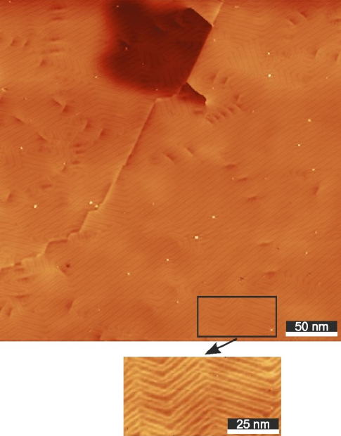
Next a 5 nm-thick Au film was deposited at RT on top of the Mo buffer layer. The Au surface was then sputtered with 1 kV Ar+ ions to remove a few AL, then annealed at 550 ∘C during 30 minutes. The resulting Au surface was studied by STM. It is atomically-flat with the usual reconstruction of AuHeyraud and Métois (1980); Sandy et al. (1991); Barth et al. (1990). However the presence of micro-grain-boundaries and dislocation loops prevent the occurrence of a perfect long range herringbone superstructure as for Au single crystals (Figure 1), its appearance being limited to restricted areas as shown in the zoom to Figure 1.
IV Co growth on Au(111)
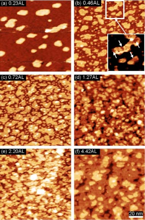
Figure 2 shows STM pictures of various amounts of Co deposited at RT on the Au surfaces described above. In the sub-atomic-layer range Co growth proceeds through the more-or-less random nucleation of 1 AL-high islands. The distribution of island lateral size is quickly bimodal (Figure 2 b-c) owing to the combination of homogeneous nucleation by adatom aggregation and heterogeneous nucleation on the Au(111) defects Nouvertné et al. (1999); Vardavas et al. (2004). The growth in this sub-atomic-layer range dramatically differs from the case of TD, for which the islands are 2 AL-high and nucleate almost solely at the elbows of the Au herringbone reconstructionVoigtländer et al. (1991), with a random 0.02 nm corrugation on the top of the islands owing to the large mismatch between Co and AuRepain et al. (2002); Fruchart et al. (2002). Here, stripe-like areas of two different heights are observed on the top of the 1 AL-high Co islands, as the zoom of a selected area in Figure 2 (b) shows (note that the vertical scale in this 25x25 nm area has been optimized to better display the top part of the islands). This feature points to some degree of intermixing between Co and Au as previously observed in PLD deposited systemsMeyerheim et al. (2007). As above mentioned, the interfacial intermixing in PLD is a result of the energy carried by the atoms or ions evaporated from the target and heated upon further interaction with the laser in the plumeSingh and Narayan (1990); Meyerheim et al. (2007). Although we set the laser fluence just above the evaporation threshold, tails in the energy distribution or hot spots in the laser beam may create a small fraction of atoms or ions carrying a few eV or more. Notice that interfacial intermixing is not a systematic feature of PLD, as we did not observe such inhomogeneities in other systems, e.g. FeJubert et al. (2003) or Co deposited on W or Mo(110). The higher bonding energy of the latter with respect to Au may prevent the intermixing. The growth mode of further Co layers proceeds close to a layer-by-layer fashion, with a morphology and inter-island distances at 4 AL of approximately 20 nm, very similar to those obtained with TDFruchart et al. (2003). Thus the topography of PLD-grown films a few AL thick is similar to their TD-grown counterparts, except for some intermixing at the bottom interface.
V Magnetic anisotropy and hysteresis
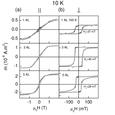
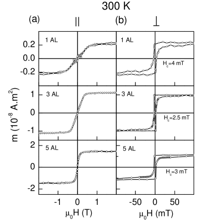
Magnetization characterization was performed on samples similar to those presented above, however immediately capped with a 2 nm thick Au layer in situ for protection against contamination (i.e., with no STM investigation). The magnetization reversal of 1, 3 and 5 AL-thick Co samples was studied by means of SQUID magnetometry, under successively in-plane and perpendicular magnetic fields, at low (Figure 3) and RT (Figure 4). Surprisingly, ferromagnetic behavior is found in all the PLD films at RT for Co coverings starting at 1 AL grown. This is an striking result since TD films of nominal thickness 1.5 AL and below are not ferromagnetic at RTChappert et al. (1986). The lower ferromagnetic critical thickness found in our PLD films stems from the different growth mode observed between both techniques. As above mentioned, for TD films Co nucleates in the form of isolated 2 AL-thick islands in relation to the herringbone reconstruction of Au(111)Heyraud and Métois (1980); Barth et al. (1990), forming crystallites of ultimately 6-10 nm in diameterCesari et al. (1989), which remain superparamagnetic until percolation occurs around 1.6 MLPadovani et al. (1999). On the other hand, in our case PLD leads to 1 AL-high Co islands at the early stages of growth, with larger lateral extends as compared to TD films (irregularly shaped islands up to 25 nm long are found at coverings around 0.72 AL as shown in Figure 2 (c)), with percolation starting at submonoatomic coverings, and thus favoring the observed ferromagnetic behavior. The accuracy of saturation magnetization measurements using SQUID on magnetic thin films is subject to several factors, including error on the estimation of the volume of the magnetic films and background diamagnetic signals that must be subtracted. After correction of the measured data, saturation magnetization values close to the bulk value () were found for the 3 and 5 AL-thick Co films, whereas a reduction around was found for the 1 AL-thick film owing to the above mentioned interdiffusion of Co and Au, being this effect specially important in the low thickness regime.
Interestingly, the remanence along the direction perpendicular to the plane and the almost closed loops in-the-plane demonstrate a full perpendicular anisotropy for all the coverings and measurement temperatures, as shown in Figure 3 and Figure 4. We analyze the magnetic anisotropy energy (MAE) at low temperature to access the values in the fundamental state. The density of MAE was computed from the hysteresis loops along the perpendicular direction as . The resulting values are summarized in Table 1. The MAE increases at low thickness, consistently with the picture of a dominant contribution of interface and/or magneto-elastic termsGradmann and Müller (1968); Gradmann (1993).
Concerning the easy axis of magnetization, the coercivity depends only weakly on the thickness. It decreases from around 30-40 mT at low temperature to typically 3-5 mT at RT. This sharp decrease with temperature is common for ultrathin films because the activation volumes involved in nucleation or activation processes underlying magnetization reversalGivord et al. (2003) are small as they scale with the thickness of the filmFerré et al. (1997); Bruno et al. (1990). Thermal activation is therefore much enhanced compared to bulk materials. Previously Au/Co/Au films had been extensively prepared using TDChappert et al. (1986) and more recently with EDCagnon et al. (2001). Both exhibit perpendicular anisotropy up to about ten AL of Co. Their total MAE has been measured mostly for films 5 AL and thicker. For 5 AL figures in the range 0.7-0.8 MJ/m3 have been givenCagnon et al. (2001); Chappert et al. (1986). This is roughly double the MAE of 5 AL-PLD-grown films (Table 1). This reduced value for our films may result from the intermixing at their lower interface. Comparison at lower thicknesses based on extrapolation using published values of volume and surface energies may be hazardous and thus is not discussed here, although a similar reduction would be expected. The case of coercivity is more striking. The coercivity at RT of 3-5 AL TD or ED films are typically in the range 35-80 mT depending on the preparation conditionsFerré et al. (1997); Bayreuther et al. (1989); Ferré et al. (1990). This is more than one order of magnitude higher than for our PLD films, an effect which obviously cannot be ascribed solely to the decreased MAE. Instead we ascribe this to the difference of growth modes, as it was done for the early onset of ferromagnetic behavior. In TD and ED the growth initially proceeds by the formation of 2 AL-high islands. This induces a significant roughness that may be responsible for the high coercivity, whereas the initial AL-growth with PLD yields smoother films, topographically and obviously magnetically. This allows the occurrence of ferromagnetism however still associated with a high coercivity as the domain wall propagation is hindered between islands. Already at 1 AL PLD films combine both ferromagnetism and a low coercivity owing to the initial growth mode in 1 AL-high islands.
Let us summarize the discussion of the relationship between the growth-modes-related microstructure and magnetic properties. Owing to the intermixing-induced initial growth mode as 1 AL-islands, PLD films compared to TD or ED films have ferromagnetic ordering already at 1 AL, a MAE reduced by and a coercivity more than one order of magnitude lower.
| 1 AL | 3 AL | 5 AL |
| 0.91 | 0.65 | 0.32 |
VI Magneto-optical (MO) activity
The magneto-optical (MO) properties of Au/Co/Au trilayers and Au/Co multilayers grown by TD as a function of the Co thickness have been extensively studiedS̆. Vis̆n̆ovský et al. (1994, 1993, 1995); Hamrle et al. (2001); Takeshita et al. (1996); Clavero et al. (2008). Vis̆n̆ovský et al.S̆. Vis̆n̆ovský et al. (1994, 1993, 1995) showed that the MO response of these systems in the thin film limit is given by the sum of one independent plus one linearly dependent term on the Co film thickness. They ascribed the independent term to different Au/Co interface effects, such as Au-Co mismatch driven stress, lattice defects, Au-Co electronic orbital hybridization and intermixing at the interfaceS̆. Vis̆n̆ovský et al. (1994). More recently, Hamrle et al.Hamrle et al. (2001) studied specifically the contribution of Co/Au interfaces to the MO response of Au/Co/Au trilayers, and concluded that the most important part of the interface contribution arises from intrinsic properties of the interface itself, i.e., from the Au-Co electronic hybridization. Nevertheless, no studies about the MO response of similar PLD grown structures have been reported so far.
Here, the MO characterization was performed on the samples presented in Section V, with graded Co thicknesses from 1 to 5 AL. Polar Kerr ellipticity spectra were measured in the spectral range from 1.4 to 4.3 eV. In this configuration, normal incident light is used, being the polarization change of the reflected light (rotation and ellipticity) measured with magnetic field applied perpendicular to the surface. As shown in Figure 5 (a), almost zero ellipticity is obtained for 1 AL, whereas a progressive increase is observed as the Co thickness increases over the entire spectral range, in accordance with previous reports on TD-grown systemsHamrle et al. (2001); S̆. Vis̆n̆ovský et al. (1995). In addition, the characteristic peak arising from the Au plasma edge is found in all the cases around 2.5 eVTakeshita et al. (1996); S̆. Vis̆n̆ovský et al. (1995, 1994, 1993).
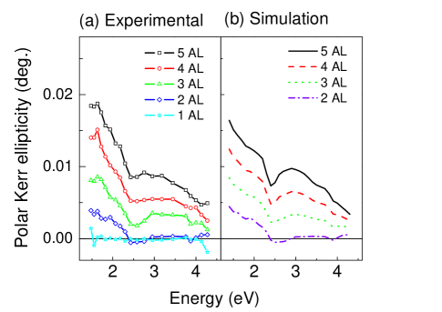
In order to model the evolution and shape of the ellipticity spectra, simulations were performed using the transfer matrix formalismSchubert (1996). As shown in Figure 5 (a), a strong effect on the ellipticity spectra due to the Au/Co interfaces is observed for the trilayers with 1 and 2 AL thick Co films, exhibiting values smaller than expected for such Co thickness considering bulk MO constantsD. Weller and Sticht (1994), in agreement with previous reportsS̆. Vis̆n̆ovský et al. (1994). In principal, the MO response of both Au/Co interfaces in the trilayers can be described by the measured MO response of the trilayer with a 2 AL thick Co film, since, as above mentioned, the MO response can be ascribed to short range Au-Co hybridization effects involving only the atomic layers closer to the interface, and in this case also some short range degree of intermixing as observed with STM. Thus, under the ultra thin film approachS̆. Vis̆n̆ovský et al. (1995), the ellipticity of the trilayers with 3, 4 and 5 AL layers thick Co films can be simulated by adding the ellipticity of 1, 2 and 3 Co thick continuous films respectively, addressing the inner part of the Co film unaffected by the interface, and the ellipticity of the trilayer with a 2 AL thick Co film, addressing the interface effects. The optical constants for Mo, Co and Au were obtained from Ref.Weaver et al. (1981) whereas bulk MO constants for Co were usedD. Weller and Sticht (1994). In fact, as shown in Figure 5 (b), simulations yield a good agreement with the measured spectra in intensity and shape for the simulated 3, 4 and 5 AL Co coverages. These results confirm that the MO response in the low Co thickness range is dominated by Au/Co interface effects, the ellipticity showing a linear response with the Co thickness for thicknesses starting at 3 AL Co, indicative of a continuous-film-like MO behavior in accordance with TD grown systemsS̆. Vis̆n̆ovský et al. (1994); Hamrle et al. (2001); Takeshita et al. (1996); S̆. Vis̆n̆ovský et al. (1995).
VII Conclusion
We fabricated epitaxial Co ultrathin films by pulsed-laser deposition on sapphire wafers buffered with a Au/Mo layer. Unlike TD-grown films which require 1.6 AL to become ferromagnetic, ferromagnetic behavior is found at room temperature for coverings starting at 1 AL. The films display perpendicular magnetization with magnetic anisotropy energy reduced by compared to TD-grown or electrodeposited films, and an unprecedented low coercivity of . We ascribed these differences to some degree of intermixing at the lower interface upon PLD. This reduces surface anisotropy, however promotes a layer-by-layer growth and thus yields a topographically and magnetically smoother film. The magneto-optical response in the low Co thickness range is dominated by Au/Co interface contributions. For thicknesses starting at 3 AL Co, the MO response has a linear dependence with the Co thickness, indicative of a continuous-film-like MO behavior.
VIII Acknowledgments
We acknowledge financial support from FP6 EU-NSF program (STRP 016447 MagDot), French National Research Agency (ANR-05-NANO-073 Vernanomag), “FUNCOAT” CONSOLIDER INGENIO 2010 CSD2008-00023, “NANOMAGMA” EU NMP-FP7-214107, “MAGPLAS” MAT2008-06765-C02-01/NAN, MAT2005-05524-C02-01 and “NANOMAGNET” CM S-0505/MAT/0194. CC acknowledges the Ministerio de Educación y Ciencia through the FPI program and R. A. Lukaszew for financial support. We are grateful to J. Ferré (LPS-Orsay) for both preliminary measurements and a critical reading of the manuscript.
References
- Horwitz et al. (1998) J. S. Horwitz, D. B. Chrisey, R. M. Stroud, A. C. Carter, J. Kim, W. Chang, J. M. Pond, S. W. Kirchoefer, M. S. Osofsky, and D. Koller, Appl. Surf. Science 127-129, 507 (1998).
- Shen et al. (2004) J. Shen, Z. Gaib, and J. Kirschner, Surf. Sci. Rep. 52, 163 (2004).
- Ohresser et al. (1999) P. Ohresser, J. Shen, J. Barthel, M. Zheng, C. Mohan, M.Klaua, and J.Kirschner, Phys. Rev. B 59, 3696 (1999).
- Singh and Narayan (1990) R. K. Singh and J. Narayan, Phys. Rev. B 41, 8843 (1990).
- Meyerheim et al. (2007) H. L. Meyerheim, M. Przybylski, A. Ernst, Y. Shi, J. Henk, E. Soyka, and J. Kirschner, Phys. Rev. B 76, 035425 (2007).
- Chappert et al. (1986) C. Chappert, D. Renard, P. Beauvillain, J. P. Renard, and J. Seiden, J. Magn. Magn. Mater. 54-57, 795 (1986).
- Cagnon et al. (2001) L. Cagnon, T. Devolder, R. Cortes, A. Morrone, J. E. Schmidt, C. Chappert, and P. Allongue, Phys. Rev. B 63, 104419 (2001).
- Fruchart et al. (2007) O. Fruchart, M. Eleoui, P.-O. Jubert, P. David, V. Santonacci, F. Cheynis, B. Borca, M. Hasegawa, and C. Meyer, J. Phys.: Condens. Matter 19, 053001 (2007).
- Cheung and Sankur (1988) J. T. Cheung and H. Sankur, CRC Critical Reviews in Solid State and Material Sciences 15, 63 (1988).
- Clavero (2007) C. Clavero, Ph.D. thesis, Universidad Autónoma de Madrid, Madrid, Spain (2007).
- Fruchart et al. (1998) O. Fruchart, S. Jaren, and J. Rothman, Appl. Surf. Sci. 135, 218 (1998).
- Heyraud and Métois (1980) J. C. Heyraud and J. J. Métois, Surface Science 100, 519 (1980).
- Sandy et al. (1991) A. R. Sandy, S. G. J. Mochrie, D. M. Zehner, K. G. Huang, and D. Gibbs, Phys. Rev. B 43, 4667 (1991).
- Barth et al. (1990) J. V. Barth, H. Brune, G. Ertl, and R. J. Behm, Phys. Rev. B 42, 9307 (1990).
- Nouvertné et al. (1999) F. Nouvertné, U. May, M. Bamming, A. Rampe, U. Korte, G. Guntherodt, R. Pentcheva, and M. Scheffler (1999).
- Vardavas et al. (2004) R. Vardavas, C. Ratsch, and R. Caflisch, Surface Science 569, 185 (2004), ISSN 0039-6028.
- Voigtländer et al. (1991) B. Voigtländer, G. Meyer, and N. M. Amer, Phys. Rev. B 44, 10354 (1991).
- Repain et al. (2002) V. Repain, G. Baudot, H. Ellmer, and S. Rousset, Mater. Sci. Engrg. B 96, 178 (2002).
- Fruchart et al. (2002) O. Fruchart, G. Renaud, J.-P. Deville, A. Barbier, F. Scheurer, M. Klaua, J. Barthel, M. Noblet, O. Ulrich, J. Mane-Mane, and J. Kirschner, J. Cryst. Growth 237-239, 2035 (2002).
- Jubert et al. (2003) P. O. Jubert, O. Fruchart, and C. Meyer, Surface Science 522, 8 (2003).
- Fruchart et al. (2003) O. Fruchart, G. Renaud, A. Barbier, M. Noblet, O. Ulrich, J.-P. Deville, F. Scheurer, J. Mane-Mane, V. Repain, G. Baudot, and S. Rousset, Europhys. Lett. 63, 275 (2003).
- Cesari et al. (1989) C. Cesari, J. P. Faure, G. Nihoul, K. Le Dang, P. Veillet, and D. Renard, J. Magn. Magn. Mater. 78, 296 (1989).
- Padovani et al. (1999) S. Padovani, I. Chado, F. Scheurer, and J.-P. Bucher, Phys. Rev. B 59, 11887 (1999).
- Gradmann and Müller (1968) U. Gradmann and J. Müller, Phys. Stat. Sol. 27, 313 (1968).
- Gradmann (1993) U. Gradmann, in Handbook of magnetic materials, edited by K. H. J. Buschow (Elsevier Science Publishers B. V., North Holland, 1993), vol. 7, chap. 1, pp. 1–96.
- Givord et al. (2003) D. Givord, M. Rossignol, and V. M. T. S. Barthem, J. Magn. Magn. Mat. 258-259, 1 (2003).
- Ferré et al. (1997) J. Ferré, V. Grolier, P. Meyer, S. Lemerle, A. Maziewski, E. Stefanowicz, S. V. Tarasenko, V. V. Tarasenko, M. Kisielewski, and D. Renard, Phys. Rev. B 55, 15092 (1997).
- Bruno et al. (1990) P. Bruno, G. Bayreuther, P. Beauvillain, C. Chappert, G. Lugert, D. Renard, J. P. Renard, and J. Seiden, J. Appl. Phys. 68, 5759 (1990).
- Bayreuther et al. (1989) G. Bayreuther, P. Bruno, G. Lugert, and C. Turtur, Phys. Rev. B 40, 7399 (1989).
- Ferré et al. (1990) J. Ferré, G. Pénissard, C. Marlière, D. Renard, P. Beauvillain, and J. P. Renard, Appl. Phys. Lett. 56, 1588 (1990).
- S̆. Vis̆n̆ovský et al. (1994) S̆. Vis̆n̆ovský, M. Nývlt, V. Prosser, R. Atkinson, W. R. Hendren, I. W. Salter, and M. J. Walker, J. Appl. Phys. 75, 6783 (1994).
- S̆. Vis̆n̆ovský et al. (1993) S̆. Vis̆n̆ovský, M. Nývlt, V. Prosser, J. Ferré, G. Pénissard, D. Renard, and G. Sczigel, J. Magn. Mag. Mat. 128, 179 (1993).
- S̆. Vis̆n̆ovský et al. (1995) S̆. Vis̆n̆ovský, M. Nývlt, V. Prosser, R. Lopušník, R. Urban, J. Ferré, G. Pénissard, D. Renard, and R. Krishnan, Phys. Rev. B 52, 1090 (1995).
- Hamrle et al. (2001) J. Hamrle, M. Nývlt, S̆. Vis̆n̆ovský, R. Urban, P. Beauvillain, R. Mégy, J. Ferré, L. Polerecký, and D. Renard, Phys. Rev. B 64, 155405 (2001).
- Takeshita et al. (1996) H. Takeshita, Y. Suzuki, H. Akinaga, W. Mizutani, K. Tanaka, T. Katayama, and A. Itoh, Appl. Phys. Lett. 68, 3040 (1996).
- Clavero et al. (2008) C. Clavero, L. Martínez, A. García-Martín, J. M. García-Martín, Y. Huttel, N. D. Telling, G. van der Laan, A. Cebollada, and G. Armelles, Phys. Rev. B 77, 094417 (2008).
- Schubert (1996) M. Schubert, Phys. Rev. B 53, 4265 (1996).
- D. Weller and Sticht (1994) R. F. C. F. A. C. D. Weller, G. R. Harp and J. Sticht, Phys. Rev. Lett. 72, 2097 (1994).
- Weaver et al. (1981) J. H. Weaver, C. Krafka, D. W. Lynch, and E. E. Koch, Physics Daten 18-1 (1981).