Tunneling anisotropic magnetoresistance in Fe/GaAs/Au junctions: orbital effects
Abstract
We report experiments on epitaxially grown Fe/GaAs/Au tunnel junctions demonstrating that the tunneling anisotropic magnetoresistance (TAMR) effect can be controlled by a magnetic field. Theoretical modelling shows that the interplay of the orbital effects of a magnetic field and the Dresselhaus spin-orbit coupling in the GaAs barrier leads to an independent contribution to the TAMR effect with uniaxial symmetry, whereas the Bychkov-Rashba spin-orbit coupling does not play a role. The effect is intrinsic to barriers with bulk inversion asymmetry.
pacs:
72.25.Dc,75.47.-mMagnetic tunnel junctions (MTJs) are prominent examples of spintronic devices Zutic2004 ; Fabian2007 and have reached already technological importance Chappert2007 . Typically, the resistance of a MTJ depends on the relative orientation of two ferromagnetic layers Zutic2004 ; Fabian2007 . Hence it came as a surprise when experiments on MTJs with only one ferromagnetic GaMnAs layer showed a sizeable spin valve effect Gould2004 . Since then, this tunneling anisotropic magnetoresistance (TAMR) effect has been observed in tunnel junctions involving various materials Ruster2005 ; Saito2005 ; Moser2007 ; Park2008 ; Ciorga2007 as well as nanoconstrictions and break junctions Giddings2005 ; Bolotin2006 ; Ciorga2007 . Amongst these experiments, the TAMR effect in Fe/GaAs/Au MTJs Moser2007 stands out due to its qualitatively different origin: Whereas the TAMR effect usually originates from properties of the magnetic layer, namely a spin-orbit induced anisotropic density of states Gould2004 ; Ruster2005 ; Saito2005 ; Park2008 ; Giddings2005 in the ferromagnet or surface states Chantis2007 ; Burton2007 ; Khan2008 , the TAMR in the Fe/GaAs/Au MTJ was attributed to an interference of Bychkov-Rashba spin-orbit coupling (SOC) at the barrier interface and the Dresselhaus SOC inside the barrier, i.e. to properties of the tunneling process itself. Moreover, the size and sign of the effect in this MTJ can be tuned by the bias voltage.
In this Letter, we show experimentally that the TAMR in Fe/GaAs/Au MTJs can also be controlled by a magnetic field. Our theoretical calculations ascribe this effect to an interplay of the orbital effects of the magnetic field and the Dresselhaus SOC in the GaAs barrier. This interplay leads to an independent TAMR contribution with uniaxial symmetry and is intrinsic to semiconductor barriers with bulk inversion asymmetry. Whereas spin-orbit effects are usually controlled through the electric field dependence of the Bychkov-Rashba SOC Zutic2004 ; Fabian2007 (bias voltage in the case of the TAMR Moser2007 ), the magnetic field dependence of the TAMR is only linked to the Dresselhaus SOC; interestingly the Bychkov-Rashba SOC does not play a role here. As we show below, this is due to the different symmetries of the SOCs. Furthermore, in our analysis we find it important to include the orbital effects of the magnetic field in both the kinetic and SOC terms of the Hamiltonian, as both terms give rise to large competing contributions, resulting in a net TAMR effect in good agreement with experiment.
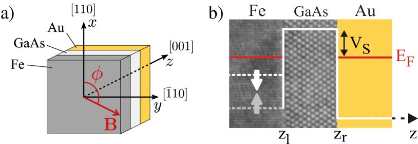
The type of tunneling device studied here is sketched in Fig. 1. We explored 8 different samples all showing the same orbital effects discussed below. We hence focus here on one sample which consists of a nm thick Fe layer, grown epitaxially on a nm thick GaAs-tunneling barrier, and a Au top electrode Moser2007 . The GaAs barrier was grown by molecular beam epitaxy on sacrificial AlGaAs layers and capped with As to prevent oxidation during transport to a UHV magnetron sputtering system. There the As cap was removed at C and Fe was grown at room temperature. Epitaxial growth of the Fe film was monitored by in-situ RHEED. The Fe-layer is finally covered with nm Co, and nm Au and serves as back contact. To prepare the top Au-contact on the other side of the GaAs tunnel barrier, the wafer is glued upside down to another substrate and the original substrate is etched away. By employing optical lithography, selective etching and UHV-magnetron sputtering a circular, m wide and nm thick Au contact is fabricated.
The measurements were carried out at a temperature of K inside a variable temperature insert of a 4He-cryostat. The device was placed in a rotatable sample holder allowing a 360∘ in-plane rotation in the magnetic field of a superconducting solenoid. The direction of with respect to the hard-axis of the Fe layer in [110]-direction (nomenclature with respect to GaAs crystallographic directions) is given by the angle (Fig. 1). The resistance drop across the tunnel barrier was measured in four-point-configuration using a HP 4155A semiconductor parameter analyzer with the Au-contact grounded.
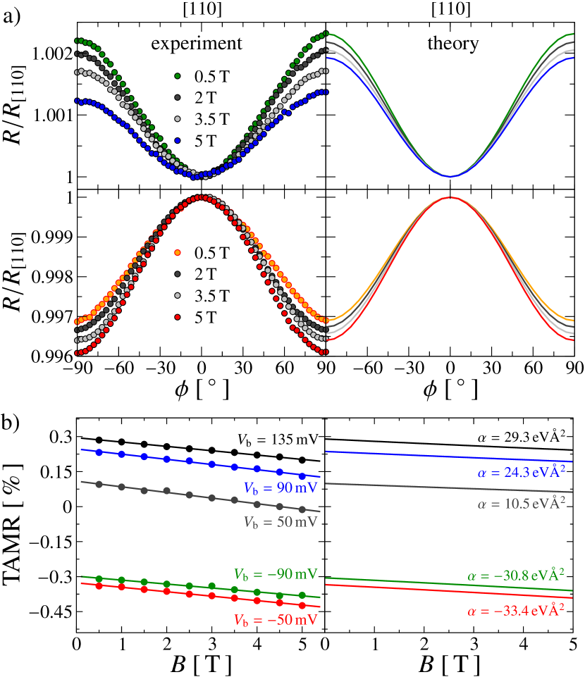
To measure the TAMR we rotated the sample by 180∘ in a constant external magnetic field. The magnetic field strength was always high enough to align the magnetization along . Fig. 2(a) shows the results of such -scans for various values of the magnetic field between 0.5 T and 5 T and the two bias voltages, mV (upper left panel) and mV (lower left panel). The TAMR shows the distinct uniaxial anisotropy characteristic for this system Moser2007 . As demonstrated recently, the TAMR strongly depends on the applied bias voltage and is connected to a bias dependent sign and strength of the Bychkov-Rashba parameter Moser2007 . For we always get a resistance maximum for mV, but a minimum for mV. This behavior is in accord with the one observed by Moser et al. Moser2007 and occurs for all samples investigated. In the simplest model the TAMR where and are Bychkov-Rashba and Dresselhaus parameters. While is a material parameter, is obtained by fitting the angular dependence (see below).
With increasing magnetic field strength both the traces for positive and negative bias voltages are bent towards lower resistance values. If we define the TAMR ratio as
| (1) |
in which is the resistance for , the magnitude of the TAMR ratio decreases for positive bias voltages but increases for negative ones. This TAMR value measured as function of is displayed in the left panel of Fig. 2(b) for magnetic field strengths up to 5 T. Note that the TAMR vanishes for a bias voltage of mV at about 4.5 T but reappears again upon further increasing . The magnetic field dependence of the TAMR ratio is in all cases linear. The slope of the best-fit line is nearly the same for all bias voltages indicating that the -dependence of the TAMR is independent of the applied voltage. The experimental data in Fig. 2 are compared to model calculations discussed below.
The importance of orbital effects for charge tunneling has been pointed out already in the literature Eaves1986 . Here, we focus on orbital effects on spin-dependent tunneling. In order to explain the experimental findings, we employ the spin-orbit based model for the TAMR effect of Refs. Moser2007 ; Fabian2007 ; MatosAbiague2009 and include the orbital effects of the magnetic field. We choose the coordinate system such that the , , and -directions are along the , , and crystallographic directions, and consider an in-plane magnetic field , where is a unit vector forming an angle with the -axis (see Fig. 1(a)). The Hamiltonian is given as , where
| (2) |
Here, , where is the magnetic vector potential and the electron charge. is a position-dependent effective mass with in the GaAs barrier and in the Fe and Au layer, where denotes the bare electron mass. is the conduction band profile in growth direction . The GaAs Schottky barrier height is given by eV. The ferromagnetism in the Fe layer is described in terms of a Stoner model Stoner1939b with spin splitting . and are chosen such that the Fermi wavevector in Fe is and for majority and minority electrons Wijn1991 , respectively, and in Au Ashcroft1988 . The Zeeman splitting in GaAs and Au is much smaller than any relevant energy scale in the system and can be neglected, as is also confirmed by numerical simulations.
The SOC due to the structural inversion asymmetry (SIA) at the Fe/GaAs-interface can be written as Bychkov1984
| (3) |
where denotes the position of the Fe/GaAs-interface. As in Refs. Moser2007 ; Fabian2007 ; MatosAbiague2009 we use the Bychkov-Rashba parameter as a fitting parameter to reproduce the bias dependence of the TAMR effect; Gmitra2009 .
Finally, the SOC due to the bulk inversion asymmetry (BIA) of the zinc-blende GaAs barrier takes the form Dresselhaus1955
| (4) |
where the bulk Dresselhaus parameter eVÅ3 in the GaAs barrier and elsewhere. Note that the orbital effects of are also included in the SOC terms.
With the gauge the Hamiltonian is translationally invariant in and -direction, and the in-plane wave vector is a good quantum number. The conductance in the Landauer-Büttiker formalism Datta2002 is then given as , where is the cross-sectional area of the junction, and is the total transmission probability (including different spin species) for the transverse wave vector at the Fermi energy . We calculate from the scattering wave functions caveatA ; those are obtained numerically from a tight-binding approximation to , using the method of finite differences on a one-dimensional grid with lattice spacing nm delta and the recursive Greens function technique Wimmer2009 .
In Fig. 2 we compare the results of the numerical simulations on the -dependence of the TAMR with the corresponding experimental data. For this, we fit the parameter at T for every value of the bias voltage to the experimental data. The dependence on can then be calculated without fitting any further parameter.
Figure 2(a) shows the angular dependence of the TAMR effect for different values of the bias voltage and magnetic field. The numerical simulations show the same trend as the experiment: The magnitude of the TAMR effect decreases with increasing , when the effect is positive, and it increases, when the effect is negative. Furthermore, the numerical calculations reproduce the experimentally found change with magnetic field within a factor of . This is an especially satisfying agreement, given the fact that the -dependence is calculated without any fitting parameter. The numerically calculated magnetic field dependence of the TAMR ratio is shown in Fig. 2(b). As the experiment, we find a linear dependence on , with a slope that is nearly independent of , i.e. the bias voltage. Again, the numerics underestimates the slope only by a small factor of .
Having established that our model is able to reproduce both qualitatively and quantitatively the experimental findings, we now develop a phenomenological model to highlight the underlying physics. In Refs. Moser2007 ; Fabian2007 ; MatosAbiague2009 it was shown that in the absence of a magnetic field, can be expanded in powers of the SOC in the form , where the are expansion coefficients and the effective spin-orbit field obtained by averaging the spin-orbit field , , over the unperturbed states of the system. The effective spin-orbit parameters are given by and . To second order in the SOC, the conductance was then found as
| (5) |
where is the angular-independent part of the conductance and a coefficient that is independent of the spin orbit parameters (for details see Refs. Fabian2007 ; MatosAbiague2009 ).
In the presence of a magnetic field, the transmission can still be expanded in powers of the SOC, albeit with -dependent coefficients and spin-orbit field . Below, we derive approximate relations for and , valid to linear order in , in terms of their counterparts at , and .
First, we consider the orbital effects of on the kinetic energy term of the Hamiltonian. The kinetic energy associated with increases the effective barrier height, and hence is sharply peaked at in the absence of a magnetic field. For however, the effective barrier height is smallest for an in-plane wave vector with and , where denotes a quantum mechanical average. Thus, the maximum of the transmission is shifted to where depends on and , and hence we assume . This shift can be interpreted as an effect of the Lorentz force. In addition to the shift of the maximum, the overall transmission decreases Eaves1986 . However, this decrease is quadratic in and will consequently be neglected. Apart from , also the effective spin-orbit field is shifted in momentum space, , where is a constant that depends on only, as the SOC terms are linear in momentum. Therefore we can in general expect .
With these approximations we can now obtain the magnetic field corrections to the conductance of Eq. (5) by evaluating in orders of the SOC. The zeroth order term remains unchanged upon integration, and the corrections to the second order term are quadratic in , thus being neglected. In contrast, the first order term that vanishes in the absence of a magnetic field Moser2007 ; Fabian2007 ; MatosAbiague2009 gives a contribution linear in :
| (6) |
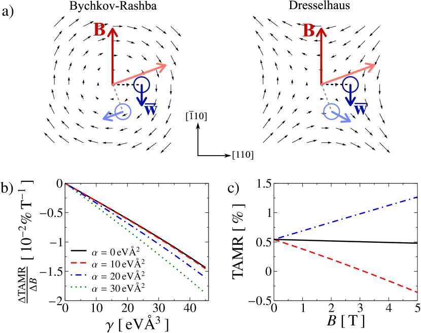
where we used the approximations of the previous paragraph and the fact that terms linear in vanish upon integration Moser2007 ; Fabian2007 ; MatosAbiague2009 . The coefficients do not depend on the spin orbit parameters. We find a different angular dependence for the Bychkov-Rashba and Dresselhaus SOC due to different symmetries of the spin-orbit fields, as shown in Fig. 3(a): The Bychkov-Rashba field exhibits rotational symmetry leading to an angular-independent contribution, whereas the interplay of and the Dresselhaus field leads to an angular dependence with uniaxial symmetry.
The total conductance in a magnetic field is then
| (7) |
valid up to second order in the SOC. The magnetic field dependence of the TAMR ratio is then
| (8) |
where we can deduce from the numerical results that the coefficients . Eq. (8) reproduces all the characteristic features of the TAMR observed in experiment: A linear -dependence, with a bias ()-independent slope. Note that the interplay of Dresselhaus SOC in the barrier and the orbital effect of the magnetic field leads to an independent contribution to the TAMR effect which turns out to have the same uniaxial symmetry as the TAMR effect in the absence of .
Finally, we verify some aspects of the phenomenological model by comparing to numerical simulations. In Fig. 3(b) we show the slope as a function of the Dresselhaus parameter that is predicted to be linear in and independent of (Eq. (8)). Indeed, we find a nearly linear dependence on and only a weak dependence on , presumably originating from higher orders in the SOC expansion. Furthermore, the coefficient in Eq. (8) depends on , i.e. opposing contributions from the kinetic and the SOC term. Fig. 3(c) shows the results of simulations where the magnetic vector potential is included only in the kinetic term (dashed line), only in the SOC term (dashed-dotted line), and in both (solid line). When the magnetic field is included in one term only, we find large TAMR effects with opposite sign that nearly cancel in the full Hamiltonian, yielding the small signal observed in experiment and in the numerics.
In summary, our experiments and theoretical considerations indicate that the interplay of the orbital effects of a magnetic field and the Dresselhaus SOC in a tunnel barrier leads to a contribution to the TAMR effect with uniaxial symmetry. This effect is predicted to an intrinsic feature of semiconductor barriers with BIA and not limited to the studied Fe/GaAs/Au tunnel junction.
We gratefully acknowledge financial support by the German Science Foundation via SFB 689.
References
- (1) I. Žutić, J. Fabian, and S. Das Sarma, Rev. Mod. Phys. 76, 323 (2004).
- (2) J. Fabian et al., Acta Phys. Slovaca 57, 565 (2007).
- (3) C. Chappert, A. Fert, and F. N. Van Dau, Nat. Mater. 6, 813 (2007).
- (4) C. Gould et al., Phys. Rev. Lett. 93, 117203 (2004).
- (5) C. Rüster et al., Phys. Rev. Lett. 94, 027203 (2005).
- (6) H. Saito, S. Yuasa, and K. Ando, Phys. Rev. Lett. 95, 086604 (2005).
- (7) J. Moser et al., Phys. Rev. Lett. 99, 056601 (2007).
- (8) B. G. Park et al., Phys. Rev. Lett. 100, 087204 (2008)
- (9) M. Ciorga et al., New J. Phys. 9, 351 (2007).
- (10) A. D. Giddings et al., Phys. Rev. Lett. 94, 127202 (2005).
- (11) K. I. Bolotin, F. Kuemmeth, and D. C. Ralph, Phys. Rev. Lett. 97, 127202 (2006).
- (12) A. N. Chantis, K. D. Belashchenko, E. Y. Tsymbal, and M. van Schilfgaarde, Phys. Rev. Lett. 98, 046601 (2007).
- (13) J. D. Burton et al., Phys. Rev. B 76, 144430 (2007).
- (14) M. N. Khan, J. Henk, and P. Bruno, J. Phys.: Condens. Matter 20, 155208 (2008).
- (15) A. Matos-Abiague and J. Fabian, Phys. Rev. B 79, 155303 (2009).
- (16) L. Eaves, K. W. H. Stevens, and F. W. Sheard, in The physics and fabrication of microstructures and microdevices, edited by M. Kelly and C. Weisbuch (Springer, Berlin, 1986).
- (17) E. C. Stoner, Proc. R. Soc. London. Ser. A 169, 339 (1939).
- (18) Magnetic Properties of Metals: d-Element, Alloys, and Compounds, edited by H. P. J. Wijn (Springer, Heidelberg, 1991).
- (19) N. W. Ashcroft and N. D. Mermin, Solid State Physics (Saunders College, Philadelphia, 1988).
- (20) Y. A. Bychkov and E. I. Rashba, J. Phys. C: Solid State Phys. 17, 6039 (1984); JETP Lett. 39, 78 (1984).
- (21) This interpretation is also supported by density functional theory: M. Gmitra, A. Matos-Abiague, C. Ambrosch-Draxl, and J. Fabian, in preparation.
- (22) G. Dresselhaus, Phys. Rev. 100, 580 (1955).
- (23) S. Datta, Electronic Transport in Mesoscopic Systems (Cambridge University Press, Cambridge, 2002).
- (24) The gauge does not allow for plane wave solutions in the contacts. Hence, we switch off away from the barrier. Since the cyclotron radius in Fe and Au is much larger than any relevant length scale (m at T), the exact position of this switching is not important.
- (25) is chosen very small to accurately approximate the -function of Eq. (3) by a rectangular function with unit area and width , centered at the Fe/GaAs-interface.
- (26) M. Wimmer, M. Scheid, and K. Richter, to appear in the Encyclopedia of Complexity and System Science (2009); arXiv:0803.3705v1.