Spin and charge pumping in magnetic tunnel junctions with precessing magnetization: A nonequilibrium Green function approach
Abstract
We study spin and charge currents pumped by precessing magnetization of a single ferromagnetic layer within or (-ferromagnet; -insulator; -normal-metal) multilayers of nanoscale thickness attached to two normal metal electrodes with no applied bias voltage between them. Both simple one-dimensional model, consisting of a single precessing spin and a potential barrier as the “sample,” and realistic three-dimensional devices are investigated. In the rotating reference frame, where the magnetization appears to be static, these junctions are mapped onto a four-terminal dc circuit whose effectively half-metallic ferromagnetic electrodes are biased by the frequency of microwave radiation driving magnetization precession at the ferromagnetic resonance (FMR) conditions. We show that pumped spin current in junctions, diminished behind the tunnel barrier and increased in the opposite direction, is filtered into charge current by the second layer to generate dc pumping voltage of the order of V (at FMR frequency GHz) in an open circuit. In devices, several orders of magnitude smaller charge current and the corresponding dc voltage appear concomitantly with the pumped spin current due to barrier induced asymmetry in the transmission coefficients connecting the four electrodes in the rotating frame picture of pumping.
pacs:
76.50.+g, 72.15.Gd, 72.25.Mk, 72.25.BaI Introduction
The pursuit of “second generation” spintronic devices Awschalom2007 has largely been focused on harnessing coherent spin states and their dynamics in metals and semiconductors. This requires to maintain and control spin orientations transverse to externally applied or internal magnetic fields. The salient example of phenomena involving both coherent spins and their time evolution is the spin-transfer torque where spin current of large enough density injected into a ferromagnetic layer either switches its magnetization from one static configuration to another or generates a dynamical situation with steady-state precessing magnetization. Ralph2008 In the reciprocal effect, termed spin pumping because it occurs in setups without applied bias voltage, Tserkovnyak2005 microwave driven precessing magnetization of a single ferromagnetic layer under the FMR conditions emits pure spin current (not accompanied by any net charge flux Nagaosa2008 ) into adjacent normal-metal layers. In the conventional picture of spin pumping, Tserkovnyak2005 interface pumps spin current in both directions, Watts2006 so that its magnitude is determined by the interfacial parameters which govern transport of spins that are noncollinear to the magnetization direction at the interface. Ralph2008 ; Tserkovnyak2005
The spin current emitted from the layer with moving magnetization has been observed Mizukami2002 ; Gerrits2006 ; Heinrich2007 in early experiments only indirectly as an enhancement of Gilbert damping Heinrich2007 of magnetization dynamics in inhomogeneous structures due to the presence of interfaces and fast relaxation of pumped spins in good “spin sink” Tserkovnyak2005 layers which ultimately leads to a loss of the angular momentum. Taniguchi2007 Very recently it has been converted Saitoh2006 into the conventionally measurable voltage signals through the inverse spin Hall effect (where longitudinal spin current injected into a metal with spin-orbit couplings generates transverse voltage between lateral edges of the sample Nagaosa2008 ). Another electrical scheme is based on multilayers Costache2006 where different voltages develop at different interfaces due to backflow spin current (driven by the spin accumulation in layers built up by directly pumped spin current), which is detected by the precessing layer itself. Wang2006g These experiments suggest that spin pumping devices could be exploited as generators Tserkovnyak2005 ; Gerrits2006 of elusive pure spin currents, Nagaosa2008 where spin current injected from into adjacent layers carries fast precessing spins in gigahertz range of frequencies offering new functionality for metal spintronics. Heinrich2007 They can also be used to probe important aspects of spin dynamics in thin layers. Taniguchi2008
Unlike spin-transfer torque that has been demonstrated in magnetic tunnel junctions (MTJ), Ralph2008 it has been considered that low transparent interfaces would completely screen the interfacial spin pumping effect (as observed in some experiments Lagae2005 ), unless the tunnel barrier has non-trivial magnetic properties. Xia2002 Thus, recent surprising measurements Moriyama2008 ; Moriyama2009 of large voltage signals of the order of V (at FMR frequencies GHz and precession cone angles ) in microwave driven and tunnel junctions, as opposed to nV pumping signals Costache2006 in multilayers, have attracted considerable theoretical attention. Chui2008 ; Xiao2008 ; Tserkovnyak2008 Nevertheless, the puzzle of unexpectedly large magnitude of the observed dc pumping voltages persists: (i) the scattering Xiao2008 approach to transport of noninteracting quasiparticles through defect-free epitaxial MTJ finds 1 nV signals at FMR frequency GHz and precession cone angle ; (ii) the tunneling Hamiltonian approach Tserkovnyak2008 for clean MTJ and the same and parameters sets the maximum dc pumping voltage at V in parallel and V in antiparallel configuration of two electrodes; and (iii) the tunneling Hamiltonian approach combined with semiclassical modeling of the interplay of spin diffusion and self-consistent screening around interfaces in and junctions involves too many unknown phenomenological parameters, thereby offering only a wide range of possible pumping voltages for both of these junctions. Chui2008
Here we address the problem of spin pumping and induced voltages by high frequency magnetization dynamics in and junctions within the framework of nonequilibrium Green function (NEGF) formalism. Haug2007 ; Nikoli'c2006 We note that NEGFs have been utilized before to study spin Wang2003a ; Hattori2007 and charge Arrachea2006 pumping by time-dependent fields acting on finite-size paramagnetic devices attached to electrodes held at the same electrochemical potential. Since NEGF formalism takes as an input a microscopic Hamiltonian, it makes it possible to include, in a controlled fashion, the full geometry Taniguchi2008a of experimental devices (such as the finite thickness of , , and layers, down to few atomic monolayers, which play an important role in the magnetoresistance Heiliger2007 and spin-transfer torque Heiliger2008 of crystalline MTJs), the properties of the insulating barrier (including disorder effects), as well as the interactions responsible for spin-flip processes in . The NEGF formalism also makes it easy to take into account ab initio input Heiliger2007 ; Heiliger2008 ; Heiliger2008b ; Waldron2007 on the interface electronic and magnetic structure and the self-consistently developed nonequilibrium spin and charge distributions around it.
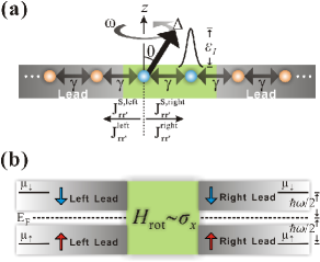
Furthermore, NEGF approach yields a remarkably transparent physical picture of pumping in ferromagnetic multilayered systems. For example, in the simplest model of pumping, generated by a single spin precessing with frequency in Fig. 1(a), the NEGF rotated into the rest frame of the spin maps the original laboratory-frame device onto a dc circuit in Fig. 1(b). The central sample of this circuit, which contains time-independent spin interactions, is attached to four electrodes that allow only one spin species to propagate through them and are, therefore, labeled by -left, -right, spin-, and spin-. These four electrodes are biased by the voltage , so that spin- electrons flow from electrodes at higher electrochemical potential and precess inside the sample due to spin-dependent interactions to be able to enter into electrodes at a lower electrochemical potential as spin- states. Thus, this picture reduces the quantitative analysis of spin and charge pumping by precessing spins to multiterminal Landauer-Büttiker-type formulas for spin-resolved charge currents as encountered in, e.g., the mesoscopic spin Hall effect. Nikoli'c2005b ; Nikoli'c2006
The paper is organized as follows. In Sec. II we exploit the physical picture of pumping provided by Fig. 1(b) to analyze local spin and charge currents flowing away from the single precessing spin toward the neighboring sites along the tight-binding chain in one-dimension (1D). This framework is extended to total pumped currents and associated voltages in three-dimensional (3D) multilayered structures, such as , , and , in Sec. III. We conclude in Sec. IV. Our principal results—pumped spin and charge currents in 1D model and voltage signals in and junctions—are shown in Figs. 2 and 5, respectively.
II NEGF approach to spin and charge pumping by a single precessing spin in one dimension
The toy 1D model in Fig. 1(a) encodes most of the essential physics of pumping by precessing spins while making it possible to obtain analytical solution for the magnitude of pumped currents. For simplicity, we start from the often employed in spin-transfer torque Theodonis2006 and spin pumping Tserkovnyak2008 studies Stoner-type Hamiltonian Fazekas1999
| (1) | |||||
in the local orbital basis suited for NEGF calculations. Haug2007 ; Nikoli'c2006 Its time dependence stems from the unit vector along the local magnetization direction, which is assumed to be spatially uniform and steadily precessing around the axis with a constant cone angle . The operators () create (annihilate) electron with spin at site , and is the nearest neighbor hopping. The coupling of itinerant electrons to collective magnetic dynamics is described through the material-dependent exchange potential , where is the vector of the Pauli matrices and denotes the Pauli matrix elements. The on-site potential accounts for the presence of the barrier [such as on the second site of the sample in Fig. 1(a)], disorder, external electric field, and it can also be used to shift the band bottom conveniently. The sample is attached to two semi-infinite ideal (spin and charge interaction free) electrodes, which terminate in macroscopic reservoirs held at the same electrochemical potential where is the Fermi energy.


The fundamental objects Haug2007 of the NEGF formalism are the retarded
| (2) |
and the lesser
| (3) |
Green functions ( denotes the nonequilibrium statistical average Haug2007 ) which describe the density of available quantum states and how electrons occupy those states, respectively. Since nonequilibrium problems are not time-translation invariant, these Green functions depend on two time variables separately. However, the cumbersome double time dependence of NEGF in general pumping problems Arrachea2006 can be eliminated Hattori2007 for the special case of time-dependent potential caused by precessing magnetization using the compensating rotation Ballentine1998 of the system described by the unitary transformation (for magnetization precessing counterclockwise). Thus, the Hamiltonian in the rotating frame Tserkovnyak2008
| (4) |
is time-independent. The term , which appears uniformly in the Hamiltonian of the sample or electrodes, will spin-split the bands of the electrodes. This yields a rotating-frame picture of pumping based on the four-terminal device in Fig. 1(b).
The device in Fig. 1(b) guides us in setting up the NEGF equations for the description of currents flowing between its four electrodes, labeled by ( and ), which are biased by the voltage . The electrodes behave effectively as the half-metallic ferromagnets, emitting or absorbing only one spin species. The rotating frame Green functions
| (5) |
and
| (6) |
depend on , or energy after the time difference is Fourier transformed. Here the advanced Green function is , and is the matrix representing in the local-orbital basis. The retarded self-energy matrix is the sum of self-energies introduced by the interaction with the leads which determine escape rates of spin- electron into the electrodes in Fig. 1(b).
For interacting systems would also contain electron-electron and electron-phonon contributions, while for noninteracting systems, described by Hamiltonian (4), the lesser self-energy is expressed in terms of as
| (7) |
The level broadening matrix
| (8) |
is obtained from the usual self-energy matrices Haug2007 of semi-infinite leads in the laboratory frame with their energy argument being shifted by to take into account the “bias voltage” in accord with Fig. 1(b). The distribution function of electrons in the four electrodes of the rotating frame dc circuit is given by
| (9) |
where for spin- and for spin-. Since the device is not biased in the laboratory frame, the shifted Fermi function in Eq. (9) is uniquely specified by the polarization or of the electrode, so that we remove the lead label from it in the equations below.
The basic transport quantity for the rotating-frame dc circuit is the spin-resolved bond charge current Nikoli'c2006 carrying spin- electrons from site to neighboring site
| (10) |
This gives spin
| (11) |
and charge
| (12) |
bond currents flowing between neighboring sites. Nikoli'c2006 Equation (10) can be evaluated analytically for 1D model assuming that for small enough we can use at zero temperature. Such “adiabatic approximation” Hattori2007 is analogous to linear-response limit in conventional transport calculations for devices biased by small voltage difference.
The -component of the bond spin current between the precessing site and its nearest neighbor in the sample, as illustrated in Fig. 1(a), is given by
| (13) | |||||
where the terms are neglected. Here is the self-energy of 1D semi-infinite lead (i.e., tight-binding chain) and . In deriving Eq. (13), we assume uniform band bottom, so that and is used to plot Fig. 1.
The expression in Eq. (13) reproduces all major features of the scattering approach Tserkovnyak2005 to adiabatic () regime of spin pumping by interface in 3D multilayers: (i) the pure spin current carrying spins is proportional to and ; (ii) component of the spin current tensor is time independent in both rotating and laboratory frames; and (iii) - and -components of the pumped spin current oscillate harmonically with time in the laboratory frame. Moreover, when potential barrier is introduced into the sample, we find in Fig. 2(a) that spin current on the right decays with increasing while pumped spin current flowing on the left increases to about twice the value of the sum of the left and right spin currents pumped symmetrically in the absence of the barrier. This effect can clarify the origin of possible Gilbert damping enhancement in realistic MTJ devices consisting of multilayers, rather than infinite electrodes, where angular-momentum loss develops due to increasing spin pumping into the left electrode even when the insulating barrier suppresses spin pumping on the right side of the junction.
Figure 2(b) demonstrates that non-zero potential also leads to concomitant pumping of a tiny charge current into the right electrode, which is several order of magnitude smaller than the pumped spin current. Unlike pumping of spins which is linear in frequency, such pumped charge current scales as . We discuss its origin in Sec. III by analyzing total charge current in the terminals expressed in terms of the transmission coefficients between the fully spin-polarized electrodes in the rotating frame.
III NEGF approach to spin and charge pumping in 3D , , and multilayers
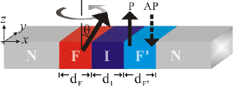
We extend this analysis to a 3D MTJ shown in Fig. 3 which consists Theodonis2006 of infinite planes of , , and materials modeled on a simple-cubic tight-binding lattice with single -orbital per site using Hamiltonian (1). The effective dc circuit [Fig. 1(b)] in the rotating frame makes it easy to write the expression for the total charge current in the left and right electrodes. For example, spin- electrons can flow from lead at higher electrochemical potential into lead at the lower electrochemical potential. They enter lead as spin- electrons with probability determined by the precession inside the sample since contains terms proportional to for which the injected spin states from lead (polarized along the axis) are not the eigenstates.
Since pumped charge current is necessarily conserved, as exemplified by Fig. 2(b), we arbitrarily select the right electrode (current flowing into the electrode is assumed to be positive) to find its explicit expression in terms of the multiterminal Landauer-Büttiker formulas Nikoli'c2005b for spin-resolved quantum transport:
| (14) | |||||
Here the transmission coefficients determine the probability for electrons injected through lead to emerge in electrode as spin- electrons. They can be computed from the NEGF-based formula Haug2007
| (15) |
which is written here in the spin-resolved form. The block of the retarded Green function matrix consists of those matrix elements which connect the layer of the sample attached to lead to the layer of the sample attached to lead .
In general, the spin current is not conserved, as illustrated by Fig. 2(a), and we choose to compute it in the left electrode:
| (16) | |||||
The expressions Eq. (14) and Eq. (16) for total currents are equivalent to the sum of all bond charge or bond spin currents, respectively, where summation is performed over the pairs of sites within the electrode at a chosen cross section. Nikoli'c2006 By the same token, the analytical expression Eq. (13) for the spin current is already equivalent to the result obtained from Eq. (16) since no summation is necessary for the cross section consisting of a single site.
The pumped charge current in multilayers with the second analyzing layer originates from spin filtering by the static magnetization of the analyzing layer of current pumped toward the right. That is, we find , and in such systems. In junctions with a single precessing layer the pumped spin current is pure if and . The possibility of nonzero pumped charge current even in junctions with only one layer whose magnetization is precessing, as exemplified by Fig. 2(b) and junctions in general [see Figs. 5(c) and 5(d)], is explained by Eq. (14) as the consequence of the asymmetry in transmission coefficients when arbitrary potential is introduced in one of the layers.
The transmission coefficients can also explain the unexpectedly large enhancement of or in Fig. 2. As the barrier height increases, and diminish to very small value while increases to about four times its value at due to quantum interferences effects on the left side of the device (quantum interferences were also found to enhance pumped spin current when coherent backscattering from disorder occurs in finite-size conductors at paramagnetic resonance Hattori2007 ). At , so that spin currents of the same magnitude are pumped in both directions symmetrically.
The pumped charge current is translated into dc voltage in open circuits via
| (17) |
where is the conductance of (or when the second layers is removed) junction sketched in Fig. 3 whose first layer has its static magnetization tilted by an angle away from the axis and the linear response bias voltage is applied between the electrodes in the laboratory frame. The quantity can also be computed via the standard NEGF formula Haug2007 as in Eq. (15) but for total , rather than spin-resolved, transmission coefficient expressed in terms of the retarded Green function and self-energies in the laboratory frame.
The largest voltage signal of spin pumping is expected in high quality epitaxial tunnel junctions. Tserkovnyak2008 To mimic their huge tunneling magnetoresistance (TMR), while using the simple single-orbital tight-binding Hamiltonian (1), we adopt the same parameters employed in Ref. Xiao2008, : eV, , eV, and the barrier height measured relative to the Fermi energy is . The band bottom is aligned across all layers of the junction with the bottom of the band for majority spins in (similarly to Ref. Xiao2008, ). The “optimistic” TMR ratio for this junction with monolayers of the insulating material is , which is close to ab initio computed zero-bias for defect-free MTJ containing five MgO layers. Waldron2007
In the coherent limit of tunneling, Waldron2007 applicable to ideal crystalline structures without any defect scattering, the in-plane wave vector is conserved and all NEGF quantities depend on it. This requires to integrate in Eq. (14) and (16) over the two-dimensional (2D) Brillouin zone (BZ). Thus, in the adiabatic limit and at zero temperature we use the following formulas to obtain the charge current
| (18) |
and the spin current in the left lead
| (19) |
pumped by magnetization precessing at frequency .
The computational algorithm for this integration can be substantially accelerated by transforming the 2D planar momentum integral into a single integral over the in-plane kinetic energy
| (20) | |||||
where we utilize the two-dimensional density of states for a square lattice and the fact that depends on through the in-plane kinetic energy . In the case of nearest-neighbor hopping on a square lattice, the kinetic energy within a monolayer is given by , where is the lattice spacing. The effect of the in-plane kinetic energy is equivalent to an increase in the on-site potential .
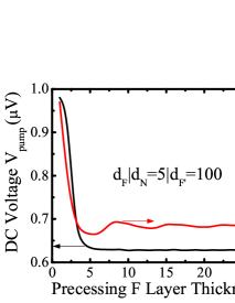
To provide reference values for understanding the magnitude of pumping voltages in tunnel junctions, as well as to connect our theory to a “standard model” of interfacial spin pumping provided by the scattering theory, Tserkovnyak2005 ; Watts2006 ; Heinrich2007 we first compute the dc voltage generated in multilayers. The chosen cone angle and FMR frequency GHz are within the range of typical values encountered in experiments Costache2006 where the results in Figs. 4 and 5 can easily be rescaled for other values of these two parameters using the general and dependence in Eq. (13). Figure 4 demonstrates that pumping involves only a thin layer of material around the interface. However, while in the scattering theory Tserkovnyak2005 adiabatic pumping develops over the atomistically short ferromagnetic coherence length , which in our junction is , we find that pumping in Fig. 5 involves about five monolayers of the ferromagnetic material. Here we assume that the magnitude of pumped current generated on this length scale is not affected Tserkovnyak2008 by spin-relaxation processes [not included in Hamiltonian (1)] that typically occur on a much longer length scale. Bass2007 The pumped voltages in both P (parallel) and AP (antiparallel) configuration are below the maximum Tserkovnyak2005 ; Xiao2008 expected voltage V (for the explanation of P and AP junction setups in the context of pumping by precessing magnetization, see Fig. 3).
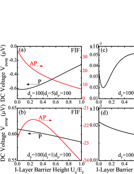
The dc pumping voltage for tunnel junctions is shown in Fig. 5. Although the presence of the potential barrier within layer of junction increases the resistance of the junction in Eq. (17), the pumped charge current decreases faster so that decreases with increasing barrier height . In contrast to the scattering result of Ref. Xiao2008, where increases with increasing for all thicknesses of the layer, we find in Fig. 5(b) such increase only if the layer consists of a single monolayer. The large difference between and configuration stems from huge TMR ratio for this junction while the magnitude of pumped charge current remains virtually the same for both P and AP configurations.
These results are quite close to V for observed in MTJs with Al2O3 barriers, and an order of magnitude larger voltages in MTJs with MgO barriers. Moriyama2009 The experimentally observed Moriyama2009 change in sign of depending on the type of the barrier (Al2O3 vs. MgO) or its thickness might be related to a difference in sign between Figs. 5(a) and 5(b). We also compute the pumped spin currents in the left and right electrodes, which do not depend on or in the range shown in Fig. 5.
Analogously to pumped charge current of 1D model in Fig. 2(b), we find nonzero charge current and corresponding dc pumping voltage in junctions shown in Figs. 5(c) and 5(d). Nevertheless, of the order of pV are way to small to explain recent experiments on junctions Moriyama2008 where V is measured at frequencies of the applied rf field in the range – GHz and the precession cone angle – tuned by the microwave input power.
IV Concluding Remarks
In conclusion, we have demonstrated that pumping of spin and charge currents by the precessing magnetization of a ferromagnetic layer within various multilayer setups consisting of , , and layers of nanoscale thicknesses can be understood within the framework of NEGF rotated into the frame moving with the magnetization as a simple four-terminal dc circuit problem, as illustrated by Fig. 1(b). The four leads of this circuit are labeled as: , , , and (i.e., they act as half-metallic ferromagnetic electrodes). They are biased by the voltage difference effectively emerging between the electrodes of opposite polarization. Our formalism provides a transparent physical picture of how: (i) single precessing spin pumps pure spin current symmetrically (in the absence of any barriers) toward the left and the right in 1D; (ii) pumped spin currents are suppressed by the tunnel barrier in one direction and enhanced in the opposite direction beyond naïve sum of currents before the introduction of the barrier; (iii) pumped spin currents develop over few monolayers of material in 3D junctions; and (iv) pumped spin currents become filtered by the second layer with static magnetization which converts them into charge current and the corresponding dc pumping voltage in open circuits. Our physical picture of spin and charge pumping in MTJs with time-dependent magnetization suggests that these setups can serve as a sensitive probe of MTJ parameters, such as the properties of the tunnel barrier and damping parameters.
The pumping voltages in tunnel junctions of the order of V at FMR frequencies GHz could explain some of the recent measurements of large voltage signals in microwave driven MTJs under the FMR conditions. Moriyama2009 They are much larger than nV signal (at FMR frequencies GHz) recently predicted by the scattering theory Xiao2008 for MTJs with similar TMR, but whose infinite electrodes are assumed to have strong spin-flip scattering leading to a vanishing spin accumulation in . Xiao2008 The spin-flip scattering can easily be introduced in Hamiltonian (1) via spin-orbit (SO) coupling terms Nikoli'c2007 whose strength is tuned to match experimental values for spin-diffusion length. Bass2007 Nevertheless, here we use simpler Hamiltonian following assumptions similar to Ref. Tserkovnyak2008, —typical spin-relaxation lengths Bass2007 are much longer than the length scale (illustrated by Fig. 4) over which pumping develops so that it does not affect the strength of pumped currents. On the other hand, computation of realistic patterns of spin accumulation Chui2008 throughout the device requires to consider balance between transport and relaxation processes. Also, the NEGF formalisms developed here, with spin-diffusion length vs selected layer thickness tuned via microscopic SO scattering terms, can tackle complicated spin pumping multilayer setups involving layers where conventional approaches are not applicable (because of spin accumulation not being well defined in an insulator). Taniguchi2008a
Although we do find nonzero charge current in multilayers when potential barrier is introduced in the device through the layer, the voltage signal pV is several orders of magnitude smaller than V observed in experiments on such devices. Moriyama2008 Also, this charge current is proportional to , rather than for spin and charge currents in junctions or experimentally observed dc voltage signal in junctions. Moriyama2008 Its origin is in asymmetry of transmission coefficients connecting the four electrodes of the dc circuit in the rotating reference frame. While the magnitude of measured voltages remains a puzzle for a variety of approaches Xiao2008 ; Tserkovnyak2008 ; Chui2008 utilized very recently to address some of the aspects of the experiment in Ref. Moriyama2008, , we believe that combining NEGF approach to spin pumping outlined here with the density functional theory (DFT) to take into account nonequilibrium self-consistent spin and charge densities (akin to NEGF-DFT approach Heiliger2008b to spin-transfer torque in spin valves and MTJs) could be capable of addressing this problem.
Acknowledgements.
We thank G. E. W. Bauer, T. Moriyama, and Y. Tserkovnyak for illuminating discussions. This work was supported by DOE Grant No. DE-FG02-07ER46374 through the Center for Spintronics and Biodetection at the University of Delaware. S.-H. Chen and C.-R. Chang also gratefully acknowledge financial support by the Republic of China National Science Council Grant No. 95-2112-M-002-044-MY3 and NSC-096-2917-I-002-127.References
- (1) D. D. Awschalom and M. E. Flatté, Nat. Phys. 3, 153 (2007).
- (2) D. C. Ralph and M. D. Stiles, J. Magn. Magn. Mater. 320, 1190 (2008).
- (3) Y. Tserkovnyak, A. Brataas, G. E. W. Bauer, and B. I. Halperin, Rev. Mod. Phys. 77, 1375 (2005).
- (4) N. Nagaosa, J. Phys. Soc. Jpn. 77, 031010 (2008).
- (5) S. M. Watts, J. Grollier, C. H. van der Wal, and B. J. van Wees, Phys. Rev. Lett. 96, 077201 (2006).
- (6) S. Mizukami, Y. Ando, and T. Miyazaki, Phys. Rev. B 66, 104413 (2002).
- (7) T. Gerrits, M. L. Schneider, and T. J. Silva, J. Appl. Phys. 99, 023901 (2006).
- (8) B. Heinrich and G. J. Woltersdorf, J. Supercond. Novel Magnetism 20, 83 (2007).
- (9) T. Taniguchi and H. Imamura, Phys. Rev. B 76, 092402 (2007).
- (10) E. Saitoh, M. Ueda, H. Miyajima, and G. Tatara, Appl. Phys. Lett. 88, 182509 (2006).
- (11) M. V. Costache, M. Sladkov, S. M. Watts, C. H. van der Wal, and B. J. van Wees, Phys. Rev. Lett. 97, 216603 (2006); M. V. Costache, S. M. Watts, C. H. van der Wal, and B. J. van Wees, Phys. Rev. B 78, 064423 (2008).
- (12) X. Wang, G. E. W. Bauer, B. J. van Wees, A. Brataas, and Y. Tserkovnyak, Phys. Rev. Lett. 97, 216602 (2006).
- (13) T. Taniguchi, S. Yakata, H. Imamura, and Y. Ando, Appl. Phys. Express 1, 031302 (2008).
- (14) L. Lagae, R. Wirix-Speetjens, W. Eyckmans, S. Borghs, and J. De Boeck, J. Magn. Magn. Mater. 286, 291 (2005).
- (15) K. Xia, P. J. Kelly, G. E. W. Bauer, A. Brataas, and I. Turek, Phys. Rev. B 65, 220401(R) (2002).
- (16) T. Moriyama, R. Cao, X. Fan, G. Xuan, B. K. Nikolić, Y. Tserkovnyak, J. Kolodzey, and J. Q. Xiao, Phys. Rev. Lett. 100, 067602 (2008).
- (17) T. Moriyama, R. Cao, X. Fan, G. Xuan, B. K. Nikolić, J. Kolodzey, and J. Q. Xiao, in preparation.
- (18) J. Xiao, G. E. W. Bauer, and A. Brataas, Phys. Rev. B 77, 180407(R) (2008).
- (19) Y. Tserkovnyak, T. Moriyama, and J. Q. Xiao, Phys. Rev. B 78, 020401(R) (2008).
- (20) S. T. Chui and Z. F. Lin, Phys. Rev. B 77, 094432 (2008).
- (21) H. Haug and A.-P. Jauho, Quantum Kinetics in Transport and Optics of Semiconductors 2nd Ed. (Springer, Berlin, 2007).
- (22) B. K. Nikolić, L. P. Zârbo, and S. Souma, Phys. Rev. B 73, 075303 (2006).
- (23) B. Wang, J. Wang, and H. Guo, Phys. Rev. B 67, 092408 (2003).
- (24) K. Hattori, Phys. Rev. B 75, 205302 (2007); J. Phys. Soc. Jpn. 77, 034707 (2008).
- (25) L. Arrachea and M. Moskalets, Phys. Rev. B 74, 245322 (2006); L. Arrachea, Phys. Rev. B 72, 125349 (2005).
- (26) T. Taniguchi and H. Imamura, Phys. Rev. B 78, 224421 (2008).
- (27) C. Heiliger, M. Gradhand, P. Zahn, and I. Mertig, Phys. Rev. Lett. 99, 066804 (2007).
- (28) C. Heiliger and M. D. Stiles, Phys. Rev. Lett. 100, 186805 (2008).
- (29) C. Heiliger, M. Czerner, B. Yu. Yavorsky, I. Mertig, and M. D. Stiles, J. Appl. Phys. 103, 07A709 (2008).
- (30) D. Waldron, L. Liu, and H. Guo, Nanotechnology 18, 424026 (2007).
- (31) B. K. Nikolić, L. P. Zârbo, and S. Souma, Phys. Rev. B 72, 075361 (2005).
- (32) I. Theodonis, N. Kioussis, A. Kalitsov, M. Chshiev, and W. H. Butler, Phys. Rev. Lett. 97, 237205 (2006).
- (33) P. Fazekas, Lecture Notes on Electron Correlations and Magnetism (World Scientific, Singapore, 1999).
- (34) L. E. Ballentine, Quantum Mechanics: A Modern Development (World Scientific, Singapore, 1998).
- (35) J. Bass and W. P. Pratt, J. Phys.: Condens. Matter 19, 183201 (2007).
- (36) B. K. Nikolić and L. P. Zârbo, Europhys. Lett. 77, 47004 (2007).