Slow Light of an Amplitude Modulated Gaussian Pulse in Cesium Vapor
Abstract
Slow light of an amplitude modulated Gaussian (AMG) pulse in cesium vapor is demonstrated and studied, as an appropriate amplitude modulation to a single pulse can expand its spectrum and thus increase the utilization efficiency of the bandwidth of a slow light system. In a single- type electromagnetically induced transparency (EIT) system, the slowed AMG pulse experiences severe distortion, mainly owing to the frequency dependent transmission of medium. Additionally, due to its spectral distribution, the frequency dependent dispersion of the medium causes simultaneous slow and fast light of different spectral components and thus a certain dispersive distortion of the AMG pulse. Further, a post-processing method is proposed to recover the slowed (distorted) pulse, which indicates that by introducing a linear optical system with a desired gain spectrum we can recover the pulse in an “all-optical” way. Finally, we discuss the limitations during this compensation procedure in detail. Although it is demonstrated in the cesium vapor using EIT, this method should be applicable to a wide range of slow light systems.
keywords:
Electromagnetically induced transparency (EIT) , slow light, Gaussian pulse , distortion, cesium vapor , amplitude modulation , delay line.PACS:
42.50.Gy , 42.50.Ct , 42.30.Lr1 Introduction
Recently, slow light has attracted tremendous attention for its potential applications in optical communication. Group velocity of an optical pulse can be slowed down using various effects, such as electromagnetically induced transparency (EIT) [1, 2], double absorption line [3, 4], coherent population oscillations [5, 6, 7], stimulated Brillouin scattering [8, 9] and stimulated Raman scattering [10], etc. Note that, most of the slow light experiments are performed using a Gaussian pulse, while a few non-Gaussian (such as rectangularly [11] and exponentially [12] shaped) pulses are studied. These studies are based on the pulse shaping, while an additional amplitude modulation to the pulse has not been well investigated yet. Moreover, the study on the slow light of a pulse with more complex spectrum should be very promising to the applications. So, we believe that an amplitude modulated pulse has a potential application in the optical communication. In this paper, we demonstrate the slow light of a cosine-type AMG pulse experimentally, and study both the absorptive and the dispersive properties of this pulse in depth.
2 Experiment
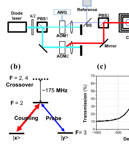
Our experimental setup is schematically illustrated in Fig. 1(a). An 852 nm narrowband (300 kHz) diode laser (output power 30 mW) is stabilized to the transition of 133Cs atom: crossover. By the combination of (half-wave plate) and PBS1, the laser is divided into two beams, the coupling and the probe, with perpendicular polarizations and adjustable proportions. The frequency of coupling laser is redshifted 175 MHz by AOM2, with the power 2.35 mW and beam diameter 2.0 mm. The probe pulse is generated by passing a weak (10 W) continuous-wave laser through AOM1, with the frequency redshifted 175 MHz and beam diameter 2.0 mm. The amplitude of probe field (nonnegative for convenience in data processing) is proportional to the amplitude of the driving RF (radio frequency) wave to AOM1, which is directly controlled by an arbitrary waveform generator (AWG). After that, both the coupling (vertically polarized) and the probe (horizontally polarized) lasers are resonant with the transition of 133Cs atom [see Fig. 1(b)], and combined at PBS2. Then, the two overlapped lasers copropagate through the cell in order to reduce the total Doppler broadening [13]. The beam splitter (BS) in front of the cell splits an appropriate portion of the probe to APD1 as reference, whose intensity is set to be equal to that of the output when the probe is detuned far off-resonant from all atomic transitions. Thus, the background absorption in experiment is eliminated and the reference can be treated as “input” in the following analysis. A 10 cm-long paraffin-coated cesium (133Cs) vapor cell at room temperature (25 ∘C) is placed in the magnetic shield (MS) to screen out the earth magnetic field in lab. The exiting beams are separated by PBS3 and only the slowed probe pulse beam reaches APD2 as the “output” in the following analysis.
In experiment, both the optical intensities of the reference (treated as “input”) and output pulses are recorded on a 100 MHz digital oscilloscope triggered by the AWG. Thus, the amplitudes of both input and output (slowed) pulses can be obtained from this relation: , which is the reason of requiring the amplitudes of probe pulses to be nonnegative in experiment. The intensities of two probe (input) pulses in time domain are chosen as
where and are the intensities of two pulses, respectively; (= 700 kHz) is the modulation frequency, (= 1) is the modulation depth, and ( 6.5 s) is the temporal duration (FWHM) of the intensity of the Gaussian pulse.
Experimental results are shown in Fig. 2. The Gaussian and the AMG pulses exhibit quite different slow light effects. In the Gaussian case, the pulse [Fig. 2(a)] is delayed by 0.47 s, with relatively low loss and little pulse distortion. Hence, we can compensate for the loss by directly amplifying the intensity of the pulse with a constant magnitude determined by the system. However, in the AMG case [Fig. 2(b)], the output pulse undergoes relatively high loss and significant distortion [meanwhile the delay time (0.14 s) is obviously decreased]. Thus, the direct amplification is not feasible any more [see the “rescaled” pulse in Fig. 2(b)].
3 Distortion due to absorption and dispersion
It is known that the pulse distortion is caused by both absorption and dispersion [14]. In an ideal EIT medium, when the coupling field () keeps unchanged both temporally and spatially, the frequency response function of the slow light system can be expressed as , where (proportional to the intensity of coupling laser) is the bandwidth of EIT spectrum, (proportional to the atomic number and cell length) is the normalized propagation length, and is the detuning of probe laser. Suppose the EIT slow-light system is linear, we have
where represents the amplitude spectrum of the input (output) pulse. Real functions [corresponding to the measured transmission spectrum in Fig. 1(c)] and are related to the absorption and dispersion, respectively.
3.1 Absorptive distortion
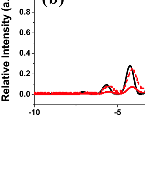
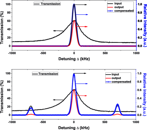
In this section, we analyze the “absorptive distortion” using the transmission spectrum [see Fig. 1(c)]. The intensity spectrums of the input and output pulses are calculated out using discrete Fourier transform (DFT) based on the experimental results. It can be seen that the intensity spectrum of the Gaussian pulse keeps unchanged with the FWHM bandwidth of 74.4 kHz [Fig. 3(a)]; by contrast, the intensity spectrum of the AMG pulse has not only a resonant Gaussian component, but also two non-resonant Gaussian sidebands with 700 kHz detunings symmetrically [Fig. 3(b)]. Since the amplitudes of the optical field and the spectrum satisfy the Fourier transform relation, this effect of generating sidebands can be analyzed through the Fourier intensity spectrums of the two input pulses:
where and are the intensity spectrums of two pulses, respectively; () is the relative intensity of the two sideband components; (determined by ) is the FWHM bandwidth of intensity spectrum of the Gaussian pulse. From the spectrum [] of the AMG pulse, we can see that the “oscillation” of intensity in time domain [, in Fig. 2(b)] is due to the interference of its three spectral components: , , and .
Note that, we have , where the phase information is eliminated, and is just the transmission spectrum of the system [see Fig. 1(c)]. Three spectral components experience different transmission rates according to the detuning (). In the AMG case, two sideband components of the pulse undergo much more severe absorptions than the resonant one. Thus, a compensation method is proposed to recover the output slowed pulse. As shown in Fig. 3, we obtain the compensated spectrums by simply amplifying the output spectrums according to the transmission spectrum, i.e., . As the compensated and the input spectrums are well overlapped in Fig. 3, we can see that it is the frequency dependent absorption that mainly causes the distortion of the AMG pulse owing to the different loss of three spectral components.
It should be mentioned that, the noise is not considered in this paper for its limited influence. Further, for a good compensation, in experiment we use a scanning probe laser with slightly higher intensity to obtain the transmission spectrum with a high SNR (signal-noise-ratio), which also causes the 10% “background transmission” as shown in Fig. 1(c). Note that, on the other hand, the probe laser (10 W) is weak enough compared to the intensive coupling laser (2.35 mW) and its influence on the transmission spectrum can be ignored. To further confirm the compensation result, we transform the compensated spectrum back to time domain using the inverse discrete Fourier transform (IDFT), and plot the input and the recovered pulses in time domain together as shown in Fig. 4. The recovered pulses of Gaussian and AMG, with different time delays, are both in good agreement with their corresponding input pulses in shape and intensity. Especially in the AMG case, even with the significant loss and distortion, both the intensity and the shape of the slowed pulse are well recovered. In addition, although this presented method is a post-processing one, a linear optical system with the corresponding gain spectrum is able to achieve this recovered result in an “all-optical” way.

3.2 Dispersive dispersion
The different spectral components, according to , also experience different phase shift, which leads to different dispersion and introduces a certain distortion that is not severe in our case. By separately transforming each spectral component back to time domain using IDFT, we obtain three Gaussian pulses with absolutely different “time-delays”. For the resonant component, we obtain the “slow light” of a Gaussian pulse [0.47 s, see Fig. 5] with an identical time delay to the non-modulated Gaussian one [0.47 s, see Fig. 4(a)]. On the contrary, for each sideband (left or right) component, we obtain a Gaussian pulse even with a little time advancing [0.18 s or 0.20 s, see Fig. 5], namely “fast light”. It should be pointed out that this phenomenon, called “simultaneous slow and fast light”, is of different spectral components of a single pulse while that presented in [15] is of two fields with the opposite polarizations in the cold Rb atoms. The intensities of the left and right sideband spectral components (fast light) in Fig. 5 have a minor difference, since they experience different absorptions due to the asymmetry of energy level structure [see Fig. 1(c)]. As a result, the time delay of the slowed AMG pulse is decreased since it is a result of the interfering superposition of these three separate spectral components, which also tells why the Gaussian and AMG pulses experience different time-delays [see Fig. 2].
On the other hand, this “simultaneous slow and fast light” effect in a single pulse will inevitably cause an additional pulse distortion (“dispersive distortion”), but here it is negligibly small for such a single- type system [16, 17]. Actually, a good compensating result has been obtained without eliminating the dispersive distortion here. However, if the dispersive distortion is so severe that a single AMG pulse splits into two or three pulses, the compensation method we proposed is no longer valid. In addition, the modulation frequency (), determining the detuning and thus the absorption and dispersion of the sideband components, have a significant impact on the compensation result. Further, there is always a residual dispersive distortion unless is small enough that all the spectral components are within the linear dispersion region of EIT spectrum. As another influencing factor, the spectral bandwidth [, inversely proportional to the temporal FWHM ()] of three components has a relatively small impact to the compensation, as long as () is not too large (small). Finally, by using the totally opposite dispersive regions, a single EIT medium can simultaneously generate slow and fast light for a single cosine-type AMG pulse with the suitable modulation frequency. In this way, this amplitude modulation increases the utilization efficiency of the bandwidth of the EIT-based slow light system.
Further, the delay time of the Gaussian pulse [0.47 s, see Fig. 2(a)] remains approximately unchanged after compensation [0.46 s, see Fig. 4(a)], because its spectrum has relatively intensive distribution within the transmission spectrum. By contrast, the delay time of the recovered AMG pulse [0.11 s, see Fig. 4(b)] is decreased after the compensating process [compared with the delay 0.14 s of the output pulse in Fig. 2(b)]. That is to say, to a certain extent, the compensation method weakens the slow light effect of the AMG pulse. This is because that, these separate spectral components propagating with definitely different group velocities (in our case, slow and fast light), are amplified by different magnitudes during the compensating process. The fast light effect of the two sideband components are enlarged more than the slow light effect of the resonant one, so that the delay time of the recovered AMG pulse, which is the interfering superposition of the three spectral components, is undoubtedly reduced. In addition, obviously, a larger modulation depth () will lead to the larger delay reduction and more significant residual distortion (caused by frequency dependent dispersion) after compensation. Therefore, when applying this compensation, two aspects need to be considered. Firstly, we should evaluate the impact of three parameters of the amplitude modulated pulse, i.e., modulation frequency (), temporal FWHM () and modulation depth (), and then determine whether a well-recovered (the residual distortion is small enough) pulse can be obtained. Secondly, we need to make a trade-off between the pulse shape (intensity) and time delay, i.e., to determine whether it is worth while to compensate the loss and distortion with such a reduction of time delay.
4 Conclusion
To our knowledge, the slow light of a cosine-type AMG pulse, which can be used to increase the utilization efficiency of the bandwidth of slow light system by using the different dispersion regions of the EIT spectrum, is demonstrated and studied for the first time. Taking the cosine-type AMG pulse as an example, we focus on studying the significant pulse distortion (loss) in a single- EIT system. Then we point out that the distortion is mainly caused by the frequency dependent transmission. Accordingly, we present a compensation method to recover the slowed pulses in shape and intensity with high fidelity, and the results also indicate that, by introducing a linear optical system with desired gain spectrum, the pulse can be recovered in an “all-optical” way. On the other hand, due to the spectral distribution of the cosine-type AMG pulse, the frequency dependent dispersion causes an (minor) additional distortion and a reduction of time delay. Meanwhile, distinguished from [15], we reveals the “simultaneous slow and fast light” effect of different spectral components in a single amplitude modulated optical pulse. Further, according to the absorptive and dispersive properties of slow light medium, the group delay and shape distortion of a pulse can be manipulated respectively, while the absorptive distortion is well compensated using the method presented in this paper. In principle, this method is applicable to any other amplitude modulated pulses, and is also extendable to many other slow light systems. It is reasonable to believe that the methods of an additional amplitude modulation to a single pulse and recovery of slowed (distorted) pulse in slow light would have potential applications in the optical communication and the low-distortion optical delay lines.
Acknowledgement
The authors appreciate A. Dang, S. Yu, C. Zhou, S. Gao, and W. Wei for the helpful discussions. This work is supported by the Key Project of the National Natural Science Foundation of China (Grant No. 60837004), and the Open Fund of Key Laboratory of Optical Communication and Lightwave Technologies (Beijing University of Posts and Telecommunications), Ministry of Education, P. R. China.
References
- [1] S. E. Harris, “Electromagnetically Induced Transparency,” Phys. Today, vol. 50, no. 7, pp. 36 C42, 1997.
- [2] M. Fleischhauer, A. Imamolu, and J. P. Marangos, “Electromagnetically induced transparency: Optics in coherent media,” Rev. Mod. Phys., vol. 77, pp. 633-673, 2005.
- [3] R. M. Camacho, M. V. Pack, J. C. Howell, A. Schweinsberg, and R. W. Boyd, “Wide-Bandwidth, Tunable, Multiple-Pulse-Width Optical Delays Using Slow Light in Cesium Vapor,” Phys. Rev. Lett., vol. 98, p. 153601, 2007.
- [4] R. M. Camacho, C. J. Broadbent, I. Ali-Khan, and J. C. Howell, “All-Optical Delay of Images using Slow Light,” Phys. Rev. Lett., vol. 98, p. 043902, 2007.
- [5] S. W. Chang, S. L. Chuang, P.-C. Ku, C. J. Chang-Hasnain, P. Palinginis, and H. Wang, “Slow light using excitonic population oscillation,” Phys. Rev. B, vol. 70, p. 235333, 2004.
- [6] P. Palinginis, F. Sedgwick, S. Crankshaw, M. Moewe, and C. J. Chang-Hasnain, “Room temperature slow light in a quantum-well waveguide via coherent population oscillation,” Opt. Express, vol. 13, pp. 9909-9915, 2005.
- [7] S. Chang, P. Kondratko, H. Su, and S. Chuang, “Slow light based on coherent population oscillation in quantum dots at room temperature,” IEEE J. Quantum Electron., vol. 43, pp. 196-205, Feb. 2007.
- [8] Y. Okawachi, M. S. Bigelow, J. E. Sharping, Z. Zhu, A. Schweinsberg, D. J. Gauthier, R. W. Boyd, and A. L. Gaeta, “Tunable All-Optical Delays via Brillouin Slow Light in an Optical Fiber,” Phys. Rev. Lett., vol. 94, p. 153902, 2005.
- [9] L. Yi, L. Zhan, W. Hu, and Y. Xia, “Delay of broadband signals using slow light in stimulated Brillouin scattering with phase-modulated pump,” IEEE Photon. Technol. Lett., vol. 19, pp. 619-621, Apr. 2007.
- [10] J. E. Sharping, Y. Okawachi, and A. L. Gaeta, “Wide bandwidth slow light using a Raman fiber amplifier,” Opt. Express, vol. 13, pp. 6092-6098, 2005.
- [11] A. B. Matsko, D. V. Strekalov, and L. Maleki, “On the dynamic range of optical delay lines based on coherent atomic media,” Opt. Express, vol. 13, pp. 2210-2223, 2005.
- [12] S. Chin and L. Thevenaz, “Optimized shaping of isolated pulses in Brillouin fiber slow-light systems,” Opt. Lett., vol. 34, pp. 707-709, 2009.
- [13] J. Gea-Banacloche, Y. Li, S. Jin, and M. Xiao, “Electromagnetically induced transparency in ladder-type inhomogeneously broadened media: Theory and experiment,” Phys. Rev. A, vol. 51, pp. 576-584, 1995.
- [14] M. D. Stenner, M. A. Neifeld, Z. Zhu, A. M. Dawes, and D. J. Gauthier, “Distortion management in slow-light pulse delay,” Opt. Express, vol. 13, pp. 9995-10002, 2005.
- [15] J. Zhang, G. Hernandez, and Y. Zhu, “Copropagating superluminal and slow light manifested by electromagnetically assisted nonlinear optical processes,” Opt. Lett., vol. 31, pp. 2598-2600, 2006.
- [16] R. W. Boyd, D. J. Gauthier, A. L. Gaeta, and A. E. Wilner, “Maximum time delay achievable on propagation through a slow-light medium,” Phys. Rev. A, vol. 71, p. 023801, 2005.
- [17] R. M. Camacho, M. V. Pack, and J. C. Howell, “Low-distortion slow light using two absorption resonances,” Phys. Rev. A, vol. 73, p. 063812, 2006.