Measuring the Neutron Lifetime Using Magnetically Trapped Neutrons
Abstract
The neutron beta-decay lifetime plays an important role both in understanding weak interactions within the framework of the Standard Model and in theoretical predictions of the primordial abundance of 4He in Big Bang Nucleosynthesis. In previous work, we successfully demonstrated the trapping of ultracold neutrons (UCN) in a conservative potential magnetic trap. A major upgrade of the apparatus is nearing completion at the National Institute of Standards and Technology Center for Neutron Research (NCNR). In our approach, a beam of 0.89 nm neutrons is incident on a superfluid 4He target within the minimum field region of an Ioffe-type magnetic trap. A fraction of the neutrons is downscattered in the helium to energies neV, and those in the appropriate spin state become trapped. The inverse process is suppressed by the low phonon density of helium at temperatures less than 200 mK, allowing the neutron to travel undisturbed. When the neutron decays the energetic electron ionizes the helium, producing scintillation light that is detected using photomultiplier tubes. Statistical limitations of the previous apparatus will be alleviated by significant increases in field strength and trap volume resulting in twenty times more trapped neutrons.
keywords:
Beta decay , Extreme ultraviolet , Liquid helium , Magnetic trap , Neutron lifetime , Scintillation , Superthermal , Ultracold neutrons , Weak interactionPACS:
14.20.Dh , 13.30.Ce , 23.35.-s , 29.25.Dz1 Introduction
The neutron lifetime is an important parameter in models of Big Bang Nucleosynthesis (BBN) as well as other aspects of physics including the number of neutrino flavors. Along with precise measurements of the neutron beta-decay correlation coefficients, the neutron lifetime can help to experimentally determine the first element in the Cabibbo-Kobayashi-Maskawa (CKM) matrix, . Precision measurements of the first row yield a strong test of the unitarity of this matrix. See recent review articles [1], [2], and [3] for a complete overview of the importance of the neutron lifetime.
A currently published average value of the neutron lifetime, () s [4], is composed of seven statistically consistent measurements using two techniques commonly referred to as “beam” and “material bottle” measurements. A single material bottle measurement, however, dominates the precision of this average. Additionally, the most recent material bottle measurement has comparable precision [5] but is not included in this average as it is more than six standard deviations discrepant from the Particle Data Group’s value. This paper describes the development of a third technique that combines magnetic confinement of neutrons with event-by-event detection of decays [6, 7]. This new approach has a fundamentally different set of systematic uncertainties than those of previous work and offers the promise of comparable statistical precision as the recent material bottle results. As such, it should play a significant role in the resolution of the current experimental situation.
2 Experimental Method
Our method utilizes ultracold neutrons (UCN) confined within a three-dimensional magnetic trap. Energy dissipation of the neutrons must occur within the trapping region due to the conservative nature of the trap. This occurs when 12 K neutrons (0.89 nm) downscatter in superfluid 4He to near rest via single phonon emission [8]. The UCN then interact with the magnetic field via their magnetic moment, . For the neutron, is anti-parallel to its spin, thus when the spin is aligned with the magnetic field, it will seek to minimize its potential energy by moving towards low field regions. The energy of the downscattered neutrons is low enough that the spin adiabatically follows the direction of the magnetic field throughout the orbit. Thus UCN with energies below the trap depth and in the low-field-seeking state are trapped.
The UCN population is thermally detached from the helium bath allowing accumulation of UCN to a density as high as , where is the superthermal production rate and is the UCN lifetime in the source. Neutron decay events are detected by turning off the cold neutron beam and observing the scintillation light created by the beta-decay electrons. When an electron moves through liquid helium, it ionizes helium atoms along its track. These helium ions quickly recombine into metastable He molecules that are in excited states. About 35 % of the initial electron energy goes into the production of extreme ultraviolet (EUV) photons from singlet decays, yielding approximately 22 photons/keV. These EUV photons are frequency down-converted to blue photons using the organic fluor tetraphenyl-butadiene (TPB) coated onto a diffuse reflector surrounding the trapping region. This light is transported via optics to room temperature and detected by two photomultiplier tubes operating in coincidence. Our detection method allows us to observe neutron decay events in situ and therefore directly measure the full decay curve.
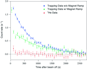
Using our prototype apparatus, neutron trapping data was taken in a number of different experimental configurations primarily for investigating systematic effects. This data is discussed in detail in Ref. [9] and shown in Fig. 1. The raw neutron decay curve exhibits a trap lifetime of s. The low central value suggests that there exist neutron trap loss mechanisms other than beta decay. These losses are a result of the presence of above threshold neutrons. We have shown that these neutrons can be removed from the trap by briefly lowering the magnetic field immediately after the loading period, causing the neutron orbits to expand and intersect the material walls where absorption can occur. As seen in Fig. 1, data collected using this field-ramping procedure exhibits a lifetime consistent with the world average, s, albeit with a large statistical uncertainty. In this data, the field was lowered to 30 % of its maximum value immediately after the neutron beam was turned off. In addition to any above threshold neutrons, the ramp flushes approximately 50 % of the fully trapped neutrons from the trap.
Using these results and our continuing studies of systematic effects, a next generation apparatus has been designed and is close to being operational. Our experimental exploration of systematic effects using the previous apparatus was severely limited by counting statistics. However, of the significant systematic uncertainties, including marginally trapped neutrons, 3He contamination, gain drift, and background subtraction, the largest were of the same order as the statistical precision. Additional studies with that apparatus would not have been productive. For example, each systematic study required approximately 7-10 days of beam-time and the entire set of data took close to one year to collect. It was essential that we incorporate our previously developed KEK trap into the apparatus to move forward.
3 Newly Developed Apparatus
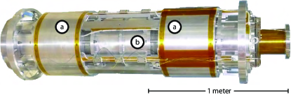
At the heart of our new apparatus is a high-current Ioffe-type magnetic trap. This trap consists of an accelerator-type superconducting quadrupole magnet that provides radial confinement combined with two aligned low-current solenoids that provide axial confinement. The quadrupole magnet is on loan from the High Energy Accelerator Research Organization (KEK) laboratory in Japan while the two solenoids were designed and constructed in collaboration with American Magnetics Inc. The new trap has a depth of 3.1 T and trapping volume of 8 l. A complete description of this and our lower-current prototype traps can be found in Ref. [10] and a photograph of the KEK trap is shown in Fig. 2.
The quadrupole operates at a current of 3400 A and the solenoids at 250 A, with both magnets protected with either silicon-controlled rectifiers (SCR) or diodes. The protection for the quadrupole, for example, uses SCRs coupled to a dump resistor to attenuate 95 % of the stored energy within 1.5 s. The current from the room-temperature power supplies is transported into the cryogenic helium bath using a pair of 5000 A high-temperature superconducting (HTS) current leads [11]. These leads significantly reduce the heat loads to the cryostat as compared to conventional vapor-cooled leads. A second set of HTS leads are used for the 250 A entry. To additionally reduce helium consumption, we incorporated into the apparatus two cryocoolers, each with 1.5 W of cooling power at 4.2 K. The total liquid helium consumption of the apparatus is held to below 100 l/day.
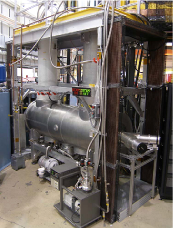
The trap assembly has been tested in the new cryostat (Fig. 3) and reached % of its design value before the first quench. Successive magnet training was not possible on this first attempt due to a malfunction in one of the cryocoolers. However, in a separate test with the magnet oriented vertically, the magnet was trained to the limit of the vapor-cooled current leads in the dewar, reaching % of the load line.
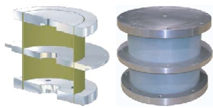
To mechanically support the magnetic trap while minimizing the heat-load into the liquid helium bath, we designed and tested two cryogenic support posts (Fig. 4) based on a design by T. Nicol et al. at Fermilab [12]. The body of each post is a 19 cm long, 19 cm diameter G-10 fiberglass tube with 1 mm wall thickness. Equally spaced aluminum flanges at 300 K, 77 K, and 4.2 K provide lateral mechanical support for the tube and bolt holes for attachments to the dewar. The posts were load tested with an active load of 1360 kg at room temperature. The heat-load from each post is calculated to be 0.35 W at 4.2 K.
A “U”-shaped dewar houses the magnetic trap and is shown in Fig. 3. On the beam-entrance end, the vertical tower houses an Oxford111Any mention of commercial products or reference to commercial organizations is for information only; it does not imply recommendation or endorsement by NIST nor does it imply that the products mentioned are necessarily the best available for the purpose. 400 3He-4He dilution refrigerator that is used for cooling the helium-filled target cell. The second tower houses the current leads for the magnets and provides a liquid helium reservoir for the superconducting magnets.
Neutrons enter the trapping region through a series of perfluoroalkoxy (PFA) Teflon/beryllium windows on the dewar [13]. Interlocking tubes of boron nitride (BN) surround the beam and shield the dewar from scattered neutrons to minimize backgrounds from neutron-induced activation. The remaining beam is absorbed at the end of the cell by the acrylic light guide. We have shown that the neutrons absorbed in the acrylic do not cause significant color center formation at our present fluences and hence will not degrade the light detection efficiency [14]. Non-trapped neutrons scattered within the helium-filled trapping region are absorbed by high-purity BN shielding (3mm wall) exterior to the light detection system. Thin carbon tubes (1mm wall) line the BN to absorb any neutron-induced luminescence originating from color center formation in the BN. The helium is contained in a stainless steel (SS) tube that extends through the length of the magnet and houses the shielding and light guides. Thermal isolation of the 25 kg cell assembly is achieved by suspension at each end by three pre-tensioned 2.6 mg/cm Zylon yarns.
The trapping region contains isotopically pure 4He (less than parts 3He [15])222For more information on Accelerator Mass Spectrometry (AMS) measurements to directly verify the isotopic purity see Ref. [16].that is cooled to mK to reduce phonon upscattering. The helium in the trapping region is thermally connected to the dilution refrigerator using a superfluid helium heat link as opposed to copper links. In addition to acting as a helium fill line, the helium heat link minimizes eddy-current heating in the cell when the magnetic field strength is changed.
The light detection system consists of a 11.4 cm outer diameter Goretex tube with a thin layer of TPB evaporated onto the inner surface. The end of the tube is viewed by a 11.4 cm diameter acrylic rod that transports the light outside the magnet bore. The light exits the mK region, passes through a 0.6 cm thick acrylic window at 4.2 K, and then into a 14 cm diameter acrylic rod that transports the light outside of the apparatus. Once exiting the vacuum region, the diameter of this light guide is reduced to 11.4 cm in order to better couple with downstream photomultiplier tubes (PMTs) through a Winston cone optimized for this geometry [17]. The light is then divided using a Y-shaped acrylic splitter to couple the light into two 12.7 cm diameter PMTs that are operated in coincidence mode to reduce uncorrelated low-temperature luminescence and dark-current backgrounds.
Pulses are digitized using transient waveform digitizers and stored for off-line analysis. This allows one to vary lower-level thresholds in software. Background events arising from cosmic rays passing through the acrylic and helium are actively vetoed using an array of scintillation paddles that surround the lower half of the apparatus. Background radiation from instruments in the surrounding area could also introduce background events, so the whole lower section of the apparatus is shielded by 10 cm of lead and 5 cm of polyethylene at room temperature. The remaining backgrounds arise from neutron-induced activation of materials within the detection region, neutron-induced luminescence, and gamma-rays Compton scattering within the acrylic.
4 Improvements and Future Directions
Data taken using our previous apparatus (Fig. 1) indicated that we were trapping approximately 3000 neutrons per fill cycle. Once the magnetic field ramping procedure was complete, approximately 1600 neutrons remained in the trap. Scaling to both the larger volume and greater depth of the new KEK trap, the number of trapped neutrons at NIST is expected be approximately , or about 5 cm-3, after a similar 30 % field ramp. Assuming that the overall detection efficiency shows the same behavior as a function of position within the trap, the observed decay rate will be increased by a factor of , allowing systematic tests to be performed in days now as opposed to the weeks required previously.
The UCN production rates have been calculated using a Monte Carlo simulation that begins with the polychromatic neutron beam, incorporates Bragg diffraction from the 0.89 nm neutron monochromator, and propagates the 0.89 nm neutrons into the measurement cell. With this code, we were able to reliably predict the number of trapped neutrons in the previous apparatus [14]. Estimates made at the early stages of this project did not fully incorporate the loss of sensitivity due to the higher-than-expected background counting rates and were thus overly optimistic.
The overall design and composition of the new apparatus has not changed significantly. That is, the cell construction, detection system, cooling system, and neutron optics are scaled versions of the previous design. This gives us high confidence in the predictions of the number of neutrons trapped as well as the detection efficiency for the new apparatus. For the sensitivity estimates, we have assumed both that the backgrounds scale appropriately with the volumes of the various components of the system and that detection efficiencies have remained the same even though improvements in both of these systems are being implemented.
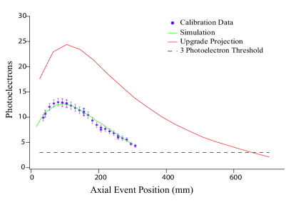
An experimental calibration of the detection efficiency using a 364 keV 113Sn beta line source was performed during the previous data collection run and has been used as a benchmark for optimizing our light collection system using the CERN Monte Carlo code called GuideIt. Modifications to this code were implemented to more realistically generate a photon source distribution in the modeled TPB geometry due to a point source of EUV photons. In reality this will be along ionization tracks in the helium with lengths on the order of a centimeter. However a point source satisfactorily reproduces the data (Fig. 5).
It was determined that two components of the previous light collection system resulted in excessive attenuation of photons and have been eliminated in the current design; the B2O3 beam stop and a sapphire window at 77 K. The beam stop was originally installed to minimize any activation and color center formation in the acrylic light guides. In independent tests, we have determined that neither of these issues are a problem and thus have removed this component in the new design. The sapphire window was included to provide good thermal conductivity for cooling the 77 K light guide, thereby reducing the heat-loads to the experimental cell. In the new design, we have extended the distance between the 77 K and 300 K end flanges such that a longer guide can be used. Based on results from an ANSYS finite element analysis of the heat flow in the new 77 K guide, the sapphire will no longer be needed. From these improvements and optimizations, we expect to gain a factor of 1.9 in average light collection efficiency, as can be seen in Fig. 5. Such an improvement will allow us to increase the lower discrimination levels and thus significantly reduce the component of the signal arising from background events.
Additionally, new designs for thermal and mechanical clamps to the 77 K light guide element will also improve performance of the new apparatus. In order to ensure the full thermal contact at 77 K and a vacuum seal at 300 K two flanges were precisely machined to have an inner diameter smaller than the outer diameter of the acrylic rod. The rod was then cooled to 77 K such that thermal contraction allowed it to slide through the room temperature flanges. However, upon simultaneous cooling of the aluminum and the acrylic, the dimensions are such that full contact of the mating surfaces will remain until temperatures are well below 77 K. Upon repeated vacuum, and cooldown cycling this guide element has reliably performed its functions.
The apparatus is presently on the beamline at the NCNR (Fig. 3). It has been successfully cooled, the magnet has been tested, helium has been liquefied into the cell and cooled with the dilution refrigerator. During our next cooldown, the goal is to introduce neutrons into the trapping volume and confirm the expected number of trapped neutrons.
In addition, we will continue to address our understanding of the largest potential source of systematic uncertainty, marginally trapped or above threshold neutrons. A 3-dimensional numerical grid of the solenoidal and quadrupole magnetic field was computed using the Radia plug-in to Mathematica software. Using a symplectic integration code [18], neutrons are then tracked through the resultant potentials in both cases where fields are static, and where the quadrupole field is ramped down and the solenoid field is fixed. Based on an optical approximation for the material Fermi potential [19] at the TPB/Goretex, BN and graphite walls of the trap, this model predicts the likelihood of the tracked neutron to be absorbed in a material surface or to be reflected back into the cell region. Thus it is used to determine the cumulative survival probability of each neutron as a function of time. We plan to quantify the ratio of the integrated survival probabilities of UCN above threshold and below threshold for various field ramping strategies. In an idealized theoretical study, we will quantify the systematic error in the mean lifetime estimate as a function of the relative fraction of surviving above threshold UCN and a decay time parameter for their survival in the trap. As a physical grounding, neutron reflectometry measurements of the cell wall materials will be performed, and these measured values will be updated in the model.
A significant benefit of the new apparatus is that the increased count rates expected will give us ample time to perform a series of systematic checks such as measuring the neutron loss due to phonon upscattering and a careful characterization of the background subtraction. Additionally, a benchmark for the model of above threshold neutrons could be obtained from the scaling of measured trap lifetime as a function of field ramp parameters. Once these systematic studies are successful, we will then pursue measuring the neutron lifetime.
Assuming the same detection efficiency (although we expect a significant improvement) and the same backgrounds from other instruments (scaled appropriately with the increased volumes of the new apparatus), we anticipate that we will be able to perform a measurement with a statistical precision corresponding to s in a 40 day reactor cycle. With the improvements discussed above, a more optimistic estimate places this value at 1.5 s. Such a measurement would play in important role in clarifying the current uncertainty surrounding the neutron lifetime.
This work was supported by the National Science Foundation under Grant Nos. PHY-0354264 and PHY-0354263 and by NIST. The neutron facilities used in this work were provided by the U.S. Department of Commerce.
References
- [1] H. Abele, Progress in Particle and Nuclear Physics 60, 1–81 (2008).
- [2] J. S. Nico and W. M. Snow, Annual Reviews of Nuclear and Particle Science 55, 27–69 (2005). arXiv:nucl-ex/0612022v1
- [3] N. Severijns, M. Beck, and O. Naviliat-Cuncic, Reviews of Modern Physics 78, 991 (2006). arXiv:nucl-ex/0605029v1
- [4] W.-M. Yao et al. (Particle Data Group), J. Phys G 33, 1 (2006)
- [5] A. Serebrov et al., Phys. Lett. B 605, 72-78 (2005). arXiv:nucl-ex/0408009v2
- [6] P. R. Huffman et al., Nature 403, 62-64 (2000). arXiv:nucl-ex/0001003v1
- [7] C. R. Brome et al., Phys. Rev. C 63, 055502 (2001). arXiv:nucl-ex/0103003v1
- [8] R. Golub and J. M. Pendlebury. Phys. Lett. 53A, 133-135 (1975).
- [9] S. N. Dzhosyuk. Magnetic Trapping of Neutrons for Measurement of the Neutron Lifetime. PhD thesis, Harvard University, 2004.
- [10] L. Yang, et al. Rev. Sci. Instrum. 79, 031301 (2008).
- [11] J. M. Lock Cryogenics 9, 438 (1969).
- [12] T. H. Nicol, J .D. Gonczy and R. C. Niemann, Design and Analysis of the SSC Dipole Magnet Super Collider 1, Plenum Press, New York, 637-649 (1989).
- [13] J. S. Butterworth et al., Rev. Sci. Instrum. 69, 3998 (1998).
- [14] C. E. H. Mattoni. Magnetic Trapping of Ultracold Neutrons Produced Using a Monocromatic Cold Neutron Beam. PhD thesis, Harvard University, 2002. Theses available at http://www.doylegroup.harvard.edu/
- [15] P. V. E. McClintock. Cryogenics 18, 201 (1978).
- [16] L. Yang. Towards Precision Measurement of the Neutron Lifetime using Magnetically Trapped Neutrons. PhD thesis, Harvard University, 2006.
- [17] W. T. Welford, and R. Winston, High Collection Nonimaging Optics (San Diego: Academic Press, 1989)
- [18] B. Yerozolimsky,et al., Phys. Lett. B 412, 240 (1997).
- [19] R. Golub, D. J. Richardson, and S. K. Lamoreaux, Ultra-Cold Neutrons (Hilger, Bristol, 1991).