Nano-indentation of circular graphene flakes
Abstract
Nano-indentation of circular graphene flakes are studied by using Molecular Dynamics simulation. We show that the theory of continuum elasticity based on nonlinear Föpple-Hencky equations is applicable on a circular suspended graphene flake. Our simulation results are plenty compatible to those results calculated by the nonlinear elasticity theory. We find the force-displacement curves in good agreement with the recent experimental measurements and conclude they are temperature independent. In addition, we find the vibration frequency for such a system and monitor that it behaves as a sinusoidal manner at small circular graphene size.
pacs:
81.05.Uw, 62.20.-x, 46.25.-y, 71.15.PdIntroduction— Understanding of the mechanical properties of graphene, a newly realized two-dimensional electron system novoselov ; geim is crucial in guiding its growth and applications. Booth et al Giem2008 have measured mechanical properties in a series of experiments on a suspended graphene and showed that graphene has an extraordinary stiffness which can supports an additional weight of many crystalline copper nano-particles. A nonlinear behavior of stress-strain response of free standing monolayer graphene has been found by Lee et al Changgu in pushing down a rigid tip of atomic force microscopy (AFM) which is placed over graphene. They determined that graphene is a very strong material as much strong as diamond. Furthermore, based on experimental measurements, a linear slope of force-displacement curves (FDCs) has been measured. frank ; scott
The physical scales available to computer simulations strongly depend on the model. In general, the level of detail that the model encompasses reduces both the number of atoms and length of times that can be simulated. A sophisticate approach is the density functional theory dft where the electronic structure of the atoms is calculated self-consistently and it can generally treat only on the system incorporate in order of several hundred atoms. Classical Molecular Dynamics simulation (MD), on the other hand is a common method to do several physical calculations for nano-indentation on various materials thesis ; diamondjournal to analysis systems containing huge number of particles with time scales on the order of nanoseconds. Accordingly, we use MD to study nano-indentation of a circular graphene flake (CGF) and to the best of our knowledge there is no any systematic study of simulated nano-indentation of the CGF.
In experiment, since the hardness of AFM’s tip is required the diamond tip material is typically used. In general, geometrical properties of the three dimensional indenter on a bulk material are important either in experiments or simulations of nano-indentation. thesis In order to check whether or not the existence of a geometric dependency, we examined two different structures, the diamond structure with carbon atoms and a face-centered cubic structure incorporating Platinum atoms, for an indentation simulation and found no indication of geometrical dependence in two dimensional graphene flake. In other words, our results indicate that the results are independent of the geometry of indenter at least in the two structures considered for the indentation problem in graphene.
The deformation of CGF under a central point load by carrying out molecular mechanics simulations has been investigated. duan In the recent work, authors used properly selected parameters and showed that the von Krmn plate theory can provide a remarkable accurate prediction of the graphene sheet behavior under linear and nonlinear bending and stretching. In the present letter, we have used the theory of elasticity based on Föpple-Hencky equations for a CGF and shown that the theory is applicable to graphene sheets by comprising the results of theory with those results calculated by MD simulations.
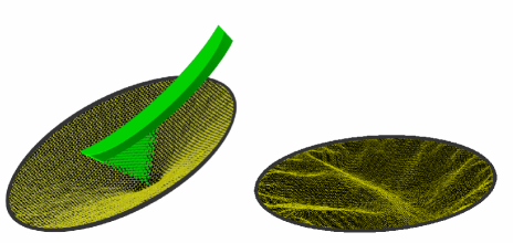
Theory and Model— We have used MD method to simulate nano-indentation of a suspended CGF. Number of carbon atoms in our simulation varies from to correspond to graphene surfaces with radius to nm, respectively. A rigidly clamped boundary condition has been employed. In our simulations, the indenter is composed of atoms. We have simulated the system at room temperature, () by employing Nos’e-Hoover thermostat. The Brenner’s bond-order potential brenner ; neek-amal has been used for carbon-carbon interactions and Van der-Waals potential for the indenter-graphene interactions erkoc2001 . For a two-component system, as studied here, the parameters for the mixed interaction between two type of atoms can be estimated by the simple average suggested by Steel et al steel . In the beginning of simulation, the lowest position of tip’s atoms is considered a few angstroms, i.e. above graphene sheet. In the load process, the indenter is pushed down slowly as over which is equivalent to a velocity equal to m/s. To avoid unphysical effects due to step time, the length of moving indenter steps was chosen to be small with respect to the force cutoff length for the interatomic potential. The indenter atoms interact only with graphene atoms via the Lennrad-Jones interactions. The shape of the indenter was chosen as a square-based pyramid as shown in Fig. 1.
We have also applied the theory of elasticity landau for the CGF under concentrated force at large deflection, . Note that a typical size of system is much larger than the deflection values, and in addition the thickness of flake is much smaller than deflection amounts.
The energetics considerations of a graphene in the limit of large deflections include both bending and stretching energies. landau The condition of minimum energy for graphene flake yields the Föppl equation. The solutions of equations can be given by using the Hencky transformations. The governing equations in planar-polar coordinate are written as follow
| (1) |
where is the radial position, is the radius of CGF, is the deflection, is the thickness of graphene approximated by 1 Å, is the Young’s modulus, is the radial stress of flake and is the concentrated load on the flake. We are interested on rigidly clamped boundary condition or fixed boundary condition in the absent of residual stress, i.e., at and it impose the following equation landau
| (2) |
where is Poisson’s ratio. Expressions given by Eq. (Nano-indentation of circular graphene flakes) are nonlinear equations. At large deflection value, the set of equations can be solved analytically cong with considering Eq. (2) and the concentrated force leads where is a complicated function of the Poisson ratio. Here where is graphene deflection at the center of CGF, in the direction. has almost a linear behavior with respect to Poisson’s ratio of desired systems and mostly varies from to for given to . Surprising enough, our simulation results confirm the concentrated force behavior which we will discuss that in discussion Section.
The mechanical properties of the free standing graphene can be probed by the tip of AFM. The experimental results have obtained for deflections greater than . Recently, the FDCs have been measured by Lee et al Changgu and they have shown that the FDCs can be approximated by a simple polynomial function having a linear term due to tension effect and a cubic term due to bending effect,
| (3) |
and thus the bending term will dominate at large deflection. The radius dependence of Hooke coefficient can be determined from the theory of elasticity safran in which the Euler-Lagrange (EL) equation of minimization of the free energy is where the and are respectively the tension and the bending rigidity and . Accordingly, the Hooke coefficient of Eq. (3) has a complicated dependence on . We have from the EL equation and it leads that . In this work, we therefore try to find a relationship between the parameter with the radius of CGF.
Discussions— Figure 1 (left panel) shows a snapshot of simulated CGF with an indenter placed over graphene (the arm of tip is shown only for clarity). The -component of forces from graphene atoms on indenter are calculated by summing over total reaction forces. Note that the deflection or displacement , of CGF is equivalent to the indenter displacement in each step. It is essential to compare the simulation results of FDCs with those measured in experiments for the cramped CGF.
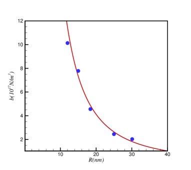
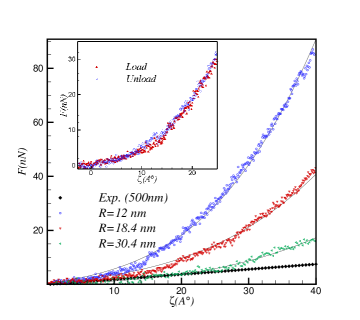
Figure 2 (top) shows the variation of applied load at as a function of graphene’s deflection in -direction. Corresponding values for parameters and have been obtained by fitting the numerical results with the expression given by Eq. (3). The size dependence of FDCs is determined in the figure. It is worthwhile to note that the sample size in the experiment possessing radius nm is much larger than the one in our simulation samples. The FDC results for nm where N/m and N/m3, are very close to the data of experiments. Note that there are defects and impurities in a real sample and those would reduce the FDCs values. Apparently, studying the indentation properties for either a tiny graphene sheet or a tiny tip should be complicated in experiment. Obviously, the physics of indentation for tiny graphene sheet can be understood based on our MD simulations.
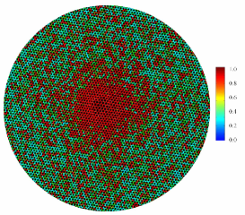
One important physics which can be extracted from our simulation is unload FDCs. In the unload case where graphene was already loaded and reached to a maximum deflection value where nm and then the indenter is pulled up, we have found that the force result in this case is the same as it in loaded case. In the inset of Fig. 2, the force results as a function of displacement for both load and unload cases are shown. It is physically known that the load and unload FDCs would be different when a bulk material is used. The physical reason is the deformation of structure make in the unload process. The distribution of stress landman on the CGF which depends on a mass density, Young’s modulus and Poisson’s ratio is shown in Fig. 2 (bottom) as well. The large stresses generated near the indenter at the center and decays fast as a function of radial value since the interaction of carbon-carbon is nonharmonic in the model interaction. In addition, the distribution of stress is no longer uniform on the surface due to the thermal fluctuations.
In order to get quantitative results, we compare the concentrated force calculated from the theory and simulation results fitted by Eq. (3) to describe the radial dependence of parameter . The parameter is given by . We have obtained the value of by simulating many CGF sizes and results are shown in Fig 3 as a function of . The value of decreases by increasing and it is fitted very well to function ( the slop of line in log-log plot is quite close to -2). It obviously means that the theory of elasticity is applicable for graphene flakes. Furthermore, we obtained that (N/m) using the fitting coefficient. Using approximated values for and , the Young modules can be obtained and it is about Terra Pascal which is very close to the value predicted by recent experiments and theoretical calculations Changgu ; scott ; fasolino . Moreover, the and are respectively obtained about N/m and eV from the fitting values of Hooke coefficient which are very close to values have been predicted for graphene. Giem2008 ; tu
Interestingly, the mechanical vibration in suspended few-layer graphene has been illustrated in experiment by using a scanning prob microscopy and found a resonance frequency about MHz. garcia From the simulation point of view, when the indenter is pulled upward from its initial position there will be a position, () where graphene sheet separates from the indenter (after the range of interaction between the carbon atoms and the indenter atoms) and the surface vibrates with high frequency. We have obtained the size dependence of frequency for one layer graphene and , and in units of GHz for , and nm, respectively shown that decreases by increasing . We monitor that the vibration frequency behaves as a sinusoidal manner at small CGF size, ( nm). Our finding regard to the frequency at small graphene size would be verified by experiments.
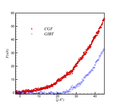
In the other hand, graphene under influence of boundary tension (GIBT) has been studied in several experiments. meyer ; Changgu It would be worth to explore the FDCs behavior of GIBT. To this purpose, we generated a GIBT by compressing the boundary of CGF about of its initial diameter and then the indenter over the GIBT is loaded with cramping boundaries condition.
We have shown a snapshot of a GIBT in Fig. 1 (right panel). The out-of plane height on the surface is around which is much bigger than the CGF where extra tensions are zero. The results of FDCs for the both cases have been shown in Fig. 4 for nm. Apparently, the force value of GIBT is smaller than one calculated for the CGF. The reason is that the number of atoms in the board range of interaction potential in the GIBT is larger than the one in the CGF and hence the attractive part of total force increases. Accordingly, the total force in this case might be smaller than the one calculated in the CGF. Consequently, the effect of boundary tension is essential for studying FDCs in comparison with the experiment measurements.
In summary, our simulation results show that the FDCs is almost independent of ordinary temperatures( up to 400 K) and they are close to the experimental data. Moreover, we found that the force on indenter in the CGF is larger than the GIBT. Importantly, the vibration frequency of the CGF in order of GHz is calculated and shown that it decreases by increasing the CGF sizes and essentially a particular vibration having a resemblance to a sinusoidal behavior occurs at small . Eventually we would like to emphasize that our numerical results show that the continuum elasticity theory can be used for the indentation problem in graphene.
We gratefully acknowledge valuable comments and discussions from F. Guinea, F. Peeters, A. Naji. M. N was supported by Sh. R. Univ. under grant program.
References
- (1) K. S. Novoselov, A. K. Geim, S. V. Morozov, D. Jiang, Y. Zhang, S. V. Dubonos, I. V. Grigorieva, and A. A. Firsov, Science 306, 666 (2004) .
- (2) A. K. Geim and K. S. Novoselov, Nature Mater. 6, 183 (2007) ; A. H. Castro Neto, F. Guinea, N. M. Peres, K. S. Novoselov and A. K. Geim, Rev. Mod. Phys. 81, 109 (2009) .
- (3) Tim J. Booth, Peter Blake, Rahul R. Nair, Da Jiang, Ernie W. Hill, Ursel Bangert, Andrew Bleloch, Mhairi Gass, Kostya S. Novoselov, M. I. Katsnelson and A. K. Geim , Nano Lett. 8, 2442 (2008) .
- (4) Changgu Lee, Xiaoding Wei, Jeffrey W Kysar and James Hone, Science 321 ,385 (2007) .
- (5) I. W. Frank, D. M. Tanenbaum, A. M. van der Zander and P. L. McEuen, J. Vac. Sci. Technol. B 25 ,2558 (2007) .
- (6) J. Bunch et al., Science 315, 490 (2007); J. Scott Bunch et al., Nano. Lett. 8 ,2458 (2008) .
- (7) W. Kohn and L. J. Sham, Phys. Rev. A 140, 1133 (1964) .
- (8) Jin-Yuan Hsieh, et al. Nanotechnology, 18, 415701 (2007); Francis Brent Neal, Ph.D Thesis, Dept. Phys and Astr. Phys. North California University (2008).
- (9) A. Richter, R. Ries, R. Smith, M. Henkel and B. Wolf, Diamond and related materials 9, 170 (2000) .
- (10) W. H. Duan and C. M. Wang, Nanothechnology 20, 075702 (2009) .
- (11) D. W. Brenner, Phys. Rev. B 42, 9458 (1990) .
- (12) N. Abedpour, M. Neek-Amal, R. Asgari, F. Shahbazi, N. Nafari, and M.R. Tabar, Phys. Rev. B 76, 195407 (2007); M. Neek-Amal, R. Asgari and M. R. Rahimitabar, Nanotechnology 20, 135602 (2009) .
- (13) S. Ercok, Ann. Rev. Comp. Phys. IX 1, 103(2001) .
- (14) H. A. Steel The Introduction of Gases with Solid Surfaces, Oxford, Pergamon (1974) .
- (15) L. D. Landau , L. P. Pitaevskii , A. M. Kosevich , E.M. Lifshitz Theory of Elasticity, Third Edition.
- (16) JIN Cong-rui, Appl. Math. Mech. -Engl. Ed. 29, 889 (2008) .
- (17) Samuel Safran Statistical Thermodynamics of Surfaces, Interfaces, and membranes (Addison-Wesley Publishing Company) (1994); Eun-Ah Kim, A. H. Castro Neto, Europhysics Letters 84, 57007 (2008) .
- (18) U. Landman, W. D. Luedtke, J. Ouyang, T. K. Xia, Jpn. J. Appl. Phys. 32, 1444 (1993) .
- (19) K. V. Zakharchenko, M. I. Katsnelson and A. Fasolino, Phys. Rev. Lett. 102, 046808 (2009) .
- (20) D. Garcia-Sanchez, et al, Nano Letter 8, 1399 (2008) .
- (21) C. Z. Tu and Z. C. Ou-Yang, Phys. Rev. B65, 233407 (2002) .
- (22) J. C. Meyer, A. K. Geim, M. I. Katsnelson, K. S. Novoselov, T. J.Booth and S. Roth, Nature 446, 60 (2007); M. Ishigami, J.H. Chen, W.G. Cullen, M.S. Fuhrer, and E.D. Williams, Nano Lett. 7, 1643 (2007) .