Phase-Induced Amplitude Apodization on centrally obscured pupils: design and first laboratory demonstration for the Subaru Telescope pupil
Abstract
High contrast coronagraphic imaging is challenging for telescopes with central obstructions and thick spider vanes, such as the Subaru Telescope. We present in this paper the first laboratory demonstration of a high efficiency PIAA-type coronagraph on such a pupil, using coronagraphic optics which will be part of the Subaru Coronagraphic Extreme-AO (SCExAO) system currently under assembly. Lossless pupil apodization is performed by a set of aspheric PIAA lenses specifically designed to also remove the pupil’s central obstruction, coupled with a Spider Removal Plate (SRP) which removes spider vanes by translating four parts of the pupil with tilted plane-parallel plates. An ”inverse-PIAA” system, located after the coronagraphic focal plane mask, is used to remove off-axis aberrations and deliver a wide field of view.
Our results validate the concept adopted for the SCExAO system, and show that the Subaru Telescope pupil can properly be apodized for high contrast coronagraphic imaging as close as 1 with no loss of sensitivity. We also verify that off-axis aberrations in the system are in agreement with theory, and that the inverse PIAA system recovers a wide usable field of view for exoplanet detection and disks imaging.
1 Introduction
While the existence of large numbers of extrasolar planets around solar type stars has been unambiguously demonstrated by radial velocity (RV), transit and microlensing surveys, attempts at their direct imaging with AO-equipped large telescopes remain largely unsuccessful. Due to modest AO performance and lack of high performance coronagraphs, the planet-rich inner parts of solar systems (including the habitable zones) are still out of the reach of current imaging surveys, which are only sensitive to planets beyond . Several recent surveys (Lafrenière et al., 2007; Biller et al., 2007; Kasper et al., 2007) indicate that massive planets on such wide orbits are rare, although recent observations have found candidates around the young A-stars HR 8799 (Marois et al., 2008), Pictoris (Lagrange et al., 2008) and Fomalhaut (Kalas et al., 2008).
Many coronagraph concepts have been developped over the last ten years, most of them derived from Bernard Lyot’s original design (Lyot, 1939). While most designs theoretically offer very high contrast, the performance is in practice severely compromised by residual wavefront errors after correction by the AO system (Racine et al., 1999; Guyon, 2005; Cavarroc et al., 2006) and by the optical layout of telescopes, especially the presence of a central obscuration and spider vanes due to the secondary mirror (Sivaramakrishnan & Lloyd, 2005; Martinez et al., 2008).
Yet a new generation of high-contrast imaging instruments is coming online: GPI on Gemini South (Macintosh et al., 2008), SPHERE on VLT (Beuzit et al., 2006) and SCExAO/HiCIAO on Subaru (Hodapp et al., 2008). They all use so-called extreme AO systems which employ deformable mirrors (DM) with large number of fast actuators and new wavefront control techniques to provide the best raw contrast () accessible from the ground in the near infrared.
In the first phase of the SCExAO project (spring 2010), a high performance PIAA coronagraph will be implemented with a 1024-actuator MEMs-based deformable mirror (DM) as an upgrade that will feed Subaru’s newly commissioned coronagraphic imager instrument HiCIAO (Hodapp et al., 2008) in the context of the Subaru Strategic Exploration of Exoplanets and Disks (SEEDS) campain. One of the key scientific drivers of HiCIAO is to use direct imaging to investigate the presence of Jovian-mass planets around young stars. Current HiCIAO observations in Angular Differential Imaging (ADI) mode using Subaru’s AO system (AO188) can only efficiently probe for companions at angular separations greater than 0.5″and reach maximum sensitivity around 1 ″. For instance, Lafrenière et al. (2007) respectively report H-band contrasts sensitivities of 9.5 and 12.9 magnitudes for these separations. SCExAO was designed to complement this search parameter space and allow to probe the innermost parts of extrasolar planetary systems. It is essentially an optical bench that will replace HiCIAO’s current fore-optics (standard Lyot coronagraph), for follow-up observations of challenging targets that would benefit from better AO corrections.
At a given angular separation, the achieveable raw contrast level in an Extreme-AO system is mostly driven by the speed and accuracy of the wavefront control system. The coronagraphic solution we report in this paper and adopted for SCExAO was designed to achieve a raw contrast at 1 angular separation in the absence of wavefront aberrations at the input of SCExAO. The system is optimized for the H-band (1.6 m).
It the first installment of the SCExAO bench, the SCExAO DM will be used to calibrate the slowly varying aberrations in order to reduce the level of quasi-static and slow moving speckles (Guyon et al., 2009). Fast correction (1 kHz correction frequency) will be provided by the 188-actuator Subaru curvature system ahead of SCExAO. A subsequent upgrade of the system will include an internal fast visible wavefront sensor that will feed the SCExAO DM and actually run in extreme AO mode. The raw contrast is then expected to improve to (detailed performance estimates are indicative rather than predictive, and subject to performance validation in a laboratory prototype currently under design). The to gain between raw contrast and detection limit will be achieved through time averaging of speckles in the focal plane, augmented by calibration and differential imaging techniques. Consequently, the coronagraph system must be designed so that it does not create fixed speckles much above the contrast level.
While static phase errors in the coronagraph can be removed by the DM, speckles or diffraction features due to amplitude errors are harder to remove by using phase on the DM: they can require large stroke and can only removed from one side of the focal plane in a relatively narrow spectral bandwidth. The SCExAO system is therefore designed to minimize such features by amplitude apodization of the pupil (including removing the large central obstruction) with a Phase Induced Amplitude Apodization (PIAA) (Guyon, 2003; Guyon et al., 2005) and removal of the pupil spider vanes by a custom Spider Removal Plate (SRP). This paper shows that these techniques do not compromize throughput or angular resolution, and allow high contrast imaging as close as 1 from the optical axis.
We introduce in §2 the design of these two key optical components of the SCExAO system and present laboratory results (§3) that validate their basic functionality. We also show that that the static aberrations these components introduce are within the correction range of the SCExAO deformable mirror, and will therefore not affect the overall SCExAO performance. Finally, our laboratory demonstration shows how the pupil remapping distorts images of off-axis sources (§4). We however demonstrate that these aberrations are well compensated by an inverse PIAA.
The tests reported in this paper were conducted with no wavefront control system, and we therefore provide no measurement of contrast performance for the SCExAO system at this time. The implementation of a wavefront control system within SCExAO will be the next step of development for this project. High contrast results with an integrated PIAA coronagraph + wavefront control system are reported in a separate paper (Guyon et al., 2009).
2 Lossless apodization of a centrally obscured beam
With a central obscuration and spider vanes, the pupil of large ground based telescope is incompatible with most high performance coronagraph concepts, although a few notable exceptions exist (see for example Roddier & Roddier (1997); Soummer (2005)).
On the Subaru Telescope pupil, the size of the central obstruction (30 %, linear) and spider thickness (22cm) require that the coronagraph is designed to remove the diffraction features they create in the focal plane. The spiders, if left uncorrected, create 4 spikes at contrast. These spikes are especially problematic at small angular separation, where their cover most of the position angle space. The central obscuration, at 30 %, creates its own set of diffraction rings with a contrast level at the peak of the central obstruction’s first ring (approximately 10 ). Any coronagraph which is designed to offer contrast better than on Subaru Telescope therefore needs to take into account the spiders and central obstruction. We note that several coronagraph concepts can be designed to mitigate the effects of such features. For example, in Lyot type coronagraphs, the pupil Lyot plane can mask most of the diffraction due to the central obstruction and spiders. This is usually achieved at the expense of coronagraph throughput (for example, a larger fraction of the pupil is masked by the Lyot mask). Martinez et al. (2008) show that this option is suitable for a contrast goal of , a spider thickness equal to 1.8 % of the pupil diameter and a coronagraph with a 2.4 inner working angle. We have not carefully evaluated this option for SCExAO, but we note that it may be difficult to implement given the large spider thickness (2.8 % of the telescope diameter) on Subaru, and the SCExAO goal to keep diffraction features due to spiders at or below contrast level at 1 from the optical axis.
The small inner working angle of the SCExAO coronagraph makes this Lyot mask approach much less efficient, as the small focal plane mask diameter creates a correspondingly large halo around the spiders ( larger than for a 2.4 inner working angle coronagraph), so a larger area would need to be masked by the Lyot stop. A variant, proposed by Abe et al. (2006) consists in inserting a complex amplitude filter in the pupil Lyot plane designed to produce a fully cleared output pupil, which can improve the throughput.
In this paper, we demonstrate the feasibility of a different approach: our coronagraph is designed to remove (or at least greatly reduce) both the spiders and central obstruction by geometrically remapping the pupil. Indeed, the classical apodization technique used on most coronagraphs reduces the effective diameter of the telescope, therefore affecting the inner working angle (to ) as well as the overall throughput. SCExAO uses a PIAA-based coronagraph, which preserves both qualities. Compared to classical apodization, this “boost” in resolution allows to probe for the presence of companions at angular separations close to one .
First, a device based on geometrical optics removes the spider vanes by translating the four ”pupil quadrants” they define toward the center of the pupil. This device, called the Spider Removal Plate (SRP), as well as its manufacturing are introduced in details in §2.1. The beam is then apodized using a Hybrid Phase Induced Amplitude Apodization scheme (Pluzhnik et al., 2006), compatible with the presence of a central obscuration. The apodizer is presented in §2.2.
2.1 A plate to remove the spider vanes
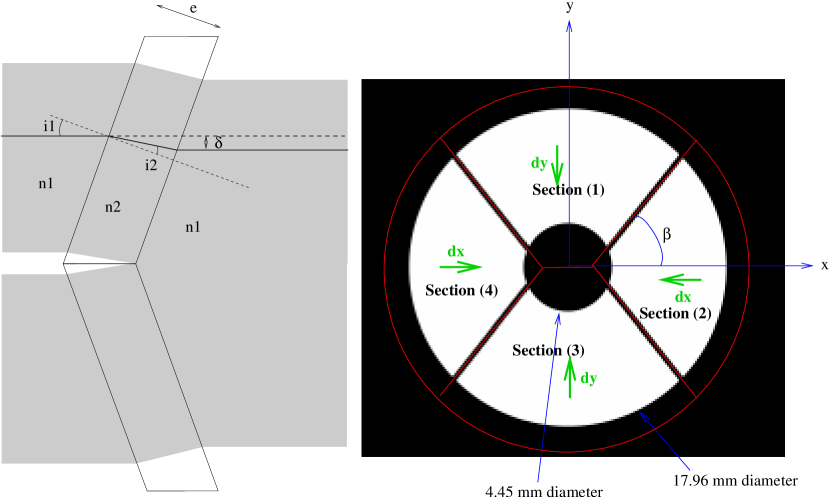
Our approach, illustrated in Figure 1, is to translate each of the four parts of the beam with a single tilted plate of glass, in a manner reminiscent of the technique of pupil densification (Labeyrie, 1996). The translations are computed to fill the gap due to the spiders. The spider vanes of the Subaru Telescope are 224 mm thick, for a total pupil diameter of 7.92 m. To account for alignment errors between the SRP and the pupil, we have chosen to design the SRP for slightly thicker (250 mm) spider vanes. The coronagraph we are assembling for Subaru is designed for an input beam of 17.96 mm in diameter. At this scale, the gap due to the spider vanes is therefore 0.453 mm. The SRP consists of four tilted plane-parallel plates, each translating a part of the pupil inwards, as shown in Figure 1. It can be best described as a “pyramid-shaped rooftop” of constant thickness. All four plates were cut from the same same plane-parallel plate (a.k.a. optical window), to guarantee, within tolerances, a constant thickness.
Commercially available optical windows have, for typical specifications, a parallelism better than five arc seconds, that is about 2.5 radians. Across a 1 cm long piece cut from such a window, the maximum wedge is going to be 0.25 microns ( in H-band) which is well within the comfort zone of a deformable mirror. All four plates of or custom component were cut from a single window of thickness mm and parallelism better than three arc seconds and the geometry of the cuts and assembly was optimized to avoid pasting together areas which originated from distant parts of the original window.
To translate a quadrant, each of the four segments of the SRP is tilted by an angle that is a function of the amplitude of the desired translation. One respectively calls and the horizontal and vertical translation of the pupil quadrants (cf. Fig. 1), and the angle between the horizontal axis and the top right vane of the Subaru Telescope pupil. The goal of the SRP beeing to fully fill the spider gap = 0.453 mm, and must verify:
| (1) |
Tilting a SRP segment by an angle not only displaces the corresponding quadrant by , it also introduces an optical path difference (OPD) relative to a hypothetical undeflected beam. The relation between the tilt angle (identical to in Fig. 1), the deplacement and the OPD come from equations of geometric optics (cf. left panel of Fig. 1):
where is the refractive index of the glass (index of air considered to be exactly one). In the small angle approximation, these relations reduce to:
| (2) | |||||
| (3) |
For the SRP to be useful, one must ensure that the OPD is the same for all four quadrants at all wavelengths, so that the wavefront of an on-axis source remains continuous at all wavelengths after the remapping. This can only be achieved when the four plates have simultaneously the same tilt angle . The solution to Eq. 1 is therefore to have = = .
For a window of thickness mm and index (Fused Silica for = 1.6 m), each plate needs to be tilted by an angle (cf. Eq. 2). To guarantee the continuity of the wavefront on-axis after remapping within , one can derive Eq. 3 relative to and find that the tolerance for the OPD translates into a constraint on the tilt angle of each plate:
| (4) |
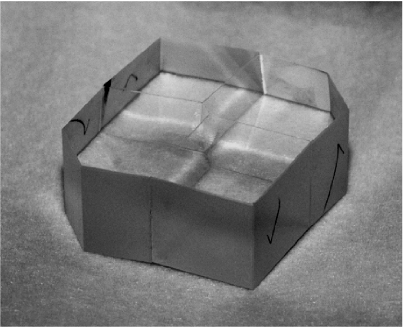
which gives a tolerance of 0.02∘ for the tilt angle. Fig. 2 shows a picture of the SRP that was assembled for the SCExAO system.
The refractive index of fused silica beeing a monotonous decreasing function of the wavelength, a simple way to ensure that the SRP fully fills the spider vanes over the entire H-band (1.485 - 1.785 m) is to optimize it for the “red side” of the band which is less deflected than the “blue side”. The two main non-ideal effects of the SRP are:
-
•
The amplitude of the lateral shifts is chromatic, and the pupil size at the SRP output is therefore wavelength dependent. This effect is however small (0.3 % over the entire H-band) and can be accounted for in the coronagraph design.
-
•
The output wavefront for off-axis sources contains “steps” which produce aberrations. These aberrations limit the useful field of view and will be quantified in §4.1. One solution to this problem is to include a “reverse-SRP” after the coronagraph but before the science camera to recover a wide field of view.
After the SRP, the beam has no spiders, but still has a central obstruction.
2.2 PIAA with a central obscuration


Although not part of the original design of Lyot (1939), apodization of the pupil has been demonstrated to provide a major enhancement of most coronagraphs (Aime & Soummer, 2003). The best apodizing function depends on the pupil geometry as well as the type of coronagraph, but prolate spheroidal functions in general have been shown to be natural apodizers for Lyot-type coronagraphs (Soummer et al., 2003), and solutions can be found for centrally obscurated pupils (Soummer, 2005).
The simplest way of performing an apodization is to insert a mask whose radial transmission profile follows such a prolate spheroidal function, the so-called classical pupil apodization (CPA). While extremely robust, and insensitive to moderate tip-tilt residuals, this approach has two main drawbacks: the throughput is low (as low as 0.1 for a contrast (Kasdin et al., 2003; Guyon et al., 2006)), and the effective pupil diameter is reduced by a factor approximately equal to the square root of the throughput (due to the fact that apodizers remove the light mostly at the edges of the pupil), which translates into a loss of angular resolution.
The Phase Induced Amplitude Apodization (PIAA) (Guyon, 2003) addresses these issues and apodizes the beam using a very different approach. It uses a set of two tailored optics working in pair: inserted in the pupil plane, the first changes the distribution of light, while the second collimates the beam for an on-axis source. While this idea has already been studied in great details (Guyon, 2003; Guyon et al., 2005; Martinache et al., 2006), this paper presents a design adapted to the presence of a central obscuration.
Pluzhnik et al. (2006) have already shown that a PIAA/CPA hybrid system is an attractive design that eases the manufacturability of the first of the two PIAA optics near the outer edge of the pupil. This is the design we have adopted for the SCExAO system. These PIAA optics are designed as a refractive system (lenses instead of mirrors). While such a choice would clearly be a risky option for a space-based coronagraph aimed at reaching very high contrast (), refractive optics can safely be used in coronagraphs for ground-based telescopes.
The set of PIAA lenses is an afocal system that leaves the pupil diameter unchanged. A low dispersion material was chosen (CaF2) to keep chromatic aberrations small. Such a refractive PIAA system has several advantages: its circular symetry makes it easier to manufacture and it is quite compact ( mm long for a 20 mm beam). Radial sag profiles of the PIAA lenses are presented in Fig. 3. The profile for L1 exhibits four main features:
-
1.
a central flat corresponding to what is left of the central obscuration after the SRP (cf. §. 2.1).
-
2.
a convex (convergent) ring that densifies the inner part of the pupil and concentrates the distribution of light toward the center of the pupil.
-
3.
a concave (divergent) ring that dilutes the outer part of the pupil. The telescope beam only illuminates L1 out to 8 mm (vertical dashed line on Fig. 3), which corresponds to the bottom of the well, where the curvature radius is smallest.
-
4.
an external flat ring that provides a convenient way of mounting the lens.
The exact shape of the lens around the outer edge of the beam is critical to the beam shaping, and greatly conditions the efficiency of the downstream coronagraph. Yet because the curvature radius of the lens is the smallest in that region, it is also where the biggest manufacturing difficulty arises.
In order to relax the manufacturing tolerances, the PIAA was designed to provide a partial apodization only, that will later be completed by a binary mask (cf. §2.3). Also, while apparently superfluous, the right-hand side of the well in the profile of L1 acts as a safeguard making the system independent of slight changes of scale in the pupil that typically accompany realignment of upstream optics. Thus, an oversized pupil that would otherwise induce light leaks sees its outermost part deflected away from the beam, preserving the performance at an acceptable (a few percents) cost in throughput.
The sag profile for L2 is complementary of L1 and exhibits three main features:
-
1.
a concave (divergent) central part that collimates the light that was densified by part of L1.
-
2.
a convex (convergent) ring that collimates the light that was remapped by part of L1.
-
3.
a flat external ring to facilitate mounting.
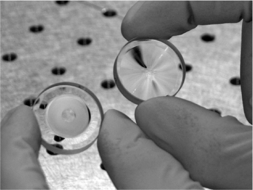
Figure 4 shows a picture of the manufactured PIAA lenses before beeing tested in the lab. The lenses are designed to be separated by 96 mm exactly at m, and adapted for a 16mm-diameter beam.

2.3 Binary mask to complete the apodization
As explained in Section 2.2, the PIAA leaves a small amount of light (0.82 % of the central surface brightness) in the outer part of the apodized pupil. To be effective, the apodization therefore needs to be completed by a CPA mask (Pluzhnik et al., 2006) in order to turn the (still) hard outer edge of the pupil into a smooth transition. To perform this complementary apodization, we chose to use a binary mask (Kasdin et al., 2005) with a series of narrow opaque rings blocking light. With this approach, the apodizer is achromatic and its transmission variations do not introduce phase variations on the pupil.
The position and width of the rings is optimized to best approximate the ideal continuous apodization profile shown in Figure 5 as the “Apodizer transmission” curve. Several constraints were imposed on the design to ensure manufacturability: no ring should be less then 1.6 m wide and the gap between consecutive opaque rings should be no less than 15 m. The resulting design is composed of 155 opaque rings for a total apodizer diameter of 11.09 mm (defined by the outer edge of the last opening between opaque rings). The apodizer was manufactured by lithography on a transmissive substrate. Figure 6 shows a microscope image of the mask.
The minimum width of the rings was limited to 1.6 m to ease manufacturing and avoid sub-wavelength features which could create strong chromatic and polarization effects. We have not done a diffraction analysis of the mask to quantify such effects, but we note that (1) a similar design with 0.8 m wide rings working in the visible did not show significant deviation from Fraunhofer diffraction theory (Guyon et al., 2009) (2) the rings are mostly affecting the outer part of the pupil where there is little incoming light.
The post-apodizer throughput over the 11.09mm diameter is 95.4%, but due to the narrow rings in the apodizer, some of the light transmitted is diffracted at large angles. The “effective” throughput of the apodizer is therefore lower, at 92.3%, and would be equal to the “raw” throughput if the apodizer were continuous instead of binary. An additional 4.8% transmission is lost because the beam is clipped by the apodizer at 69.3% of the nominal 16 mm beam diameter. This clipping is equivalent to clipping the outer 2.5% of the input telescope beam at the entrance of the PIAA system, and relaxes pupil alignment tolerances at the expense of a 4.8% throughput loss and a 2.5% angular resolution loss. The combined throughput from (1) absorption in the apodizer, (2) diffractive losses in the apodizer and (3) beam clipping is 87.5%. We note that most of these losses could be reduced with a more aggressive design with tighter tolerances, but we decided for this first on-sky PIAA system to keep the design more conservative.
3 Laboratory testing
3.1 Optical layout
Because of its specific design: incoming and outcoming beams are collimated, and the aspheric surfaces face each other, the PIAA can work over a broad range of wavelengths. The distance between the two PIAA lenses can compensate for the change of refraction index when changing wavelength. This allowed us to test the optics in visible light, using a standard laser diode ( nm) as our light source, although the system is optimized for the H-band (m).
We have chosen to test the remapping optics (PIAA optics and SRP) with visible light for convenience. The optics were designed for near-IR wavelength, but their functionality can be tested with visible light although near-IR optimized anti-reflection coatings create ghosts. We note that a high contrast coronagraphic imaging test would require near-IR light in addition to wavefront correction with a deformable mirror, but in the absence of wavefront control, testing at a wavelength almost three times shorter than nominal provides much higher sensitivity to aberrations as well as alignment errors.
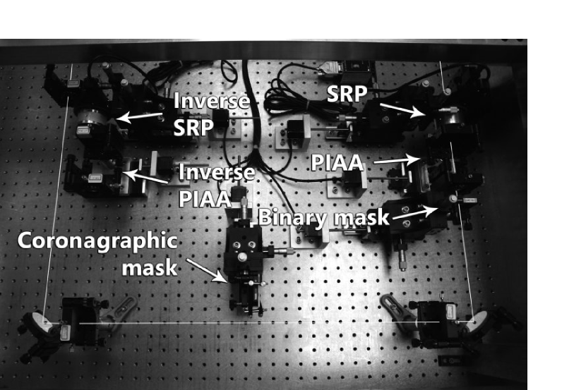
Except for the wavefront control system that is not tested in this laboratory demonstration, the test bed is close to the system to be installed onto the Nasmyth platform of the Subaru Telescope, after the 188-actuator AO system and before HiCIAO (Hodapp et al., 2008). Figure 7 provides an overview of the system. On the sketch, a 17 mm collimated beam comes horizontally from the bottom-right corner, and goes through a mask simulating the Subaru pupil. The beam then goes through the SRP (see §2.1), the PIAA (see §2.2) and the binary mask (cf. §2.3). At this point, the beam is suitably shaped for high-performance coronagraphy.
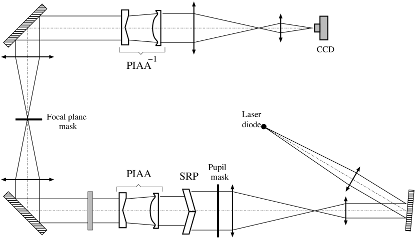
The light reflects off a flat mirror and travels from bottom to top through a first achromatic doublet that provides the first focal plane where a coronagraphic mask is inserted, and another achromatic doublet that provides another pseudo-pupil plane downstream.
The light then reflects off the top-left flat mirror and goes toward the left, through an exact replica of the first PIAA system, only mounted backwards. The motivation for this will be discussed in §4.2. A two-doublet system makes an image on a CCD camera that can be placed either in the pupil or the image plane.
Each element (c.f. bottom picture of Fig. 7) is mounted on a motorized translation stage to be removed from the optical train in a few seconds. This provides good flexibility, and permits the testing of multiple combinations for diagnostic, to the extent that even if all “active” elements (SRP and PIAA) are taken off the beam, the system still works as a perfectly functional non-apodized Lyot coronagraph.
3.2 Image acquisition and processing
All acquisitions are made by a 1600x1200 pixels CCD camera (7.4 m square pixels). A optical density of 2 is used to avoid saturation. Each image is cleaned by removing bias and hot pixels, and for each simulation, we align and coadd 20 acquisitions to reduce readout and photon noises.
The final two-doublet system mentioned in §3.1 was chosen to provide sampling better than Nyquist in the image plane, while still allowing to image the pupil with a sufficient number of pixels to observe the effect of the PIAA and the SRP. With these “active” elements out of the beam, the retained configuration provides 2.3 pixels per and 390 pixels in diameter for the pupil of the telescope.
3.3 Effect of the SRP

Figure 8 demonstrates the effect of the SRP, whose design and specifications are discussed in §2.1. The figure compares images of the pupil (left column) and the corresponding PSFs (right column) taken with and without the SRP in the beam.
The effect of the suppression of the spider vanes is clearly visible as the diffraction spikes present in the standard imaging mode PSF (top right image of Fig. 8) are diminished when the SRP is introduced into the beam (bottom right image of same figure). Thinner spiders are however still present and contribute to weak diffraction spikes in the images. This incomplete suppression of the spiders can be attributed to the finite thickness of the glue holding the quadrants together in the SRP.
Since no wavefront control system was used while conducting these tests, nothing compensates the aberrations introduced by the SRP, which beeing imperfect, necessarily deteriorates the quality of the PSF. In order to offer a basis for comparison, the central column of figure 8 presents simulated versions of the same images. Each PSF simulation was calculated by using the square root of its corresponding pupil image for amplitude and constant phases. Without the SRP, a comparison of simulated and experimental images is convincing evidence that the relaying lenses and mirrors are sufficiently well-aligned not to introduce any obvious aberrations.
When inserting the SRP, the deterioration of the image quality is non-negligible. Repeated measurements of a Strehl ratio with the SRP ( without) offer an estimate of the RMS aberration it introduces through:
| (5) |
which for nm gives a RMS wavefront aberration nm. For reference, for m, the same component would provide a Strehl ratio .
This wavefront error, since it is static, does not have an impact on the final PSF quality as long as (1) it is measured by the wavefront sensor and (2) it is within the correction range of the deformable mirror. The SCExAO architecture will include a wavefront sensor at the science focal plane, and the SCExAO’s DM stroke is about 1 m. Since the remapping introduced by the SRP will turn a continuous wavefront error into a sharp step, a DM located after the SRP cannot easily correct such wavefront errors. The SCExAO’s DM will therefore be located before the SRP.
Because it is index-dependent (see equation 2), the displacement is a function of the wavelength and will go from = 0.402 mm for m to = 0.410 mm for nm.
We note that beeing optimized for the near-infrared, the coating of the SRP is partially reflective (transmission T=0.89) at the test wavelength. The pupil image with the SRP (Fig 8, lower left) shows that each quadrant of the SRP creates a ghost toward the outside of the pupil. These ghosts will be considerably fainter in the near-IR wavelength for which the coatings have been designed.”
For now the tip-tilt of the SRP is controlled by two manual micrometer drives, with an accuracy of a few arc seconds. In the final system, higher accuracy remotely controlled actuators will be used.
3.4 Pupil apodization

The role of the apodization is to turn the hard-edge pupil, responsible for the presence of rings in the PSF into the ideal prolate spheroidal that will maximize the coronagraphic null. In this system, the apodization is a three-step process that combines the SRP, the PIAA and the binary mask.
Figure 9 plots pupil radial profiles measured with our experiment using different combinations of these three elements, to illustrate how each affects the pupil.
The effect of the SRP on the pupil profile is minimum. To fill up the gap due to the spider vanes, it moves the four quadrants inwards by 0.4 mm. The pupil beeing 9 mm in radius, this translates into the 4.5 % pupil size reduction observed when comparing the solid and dashed line profiles in Fig. 9. Note that the central obscuration shrinks by the same amount. Section 4.2 will show how this apparent reduction of the pupil diameter does not also translate into a penalty in angular resolution.
The PIAA has a much more dramatic effect on the pupil. It takes the light that was uniformly distributed in the original pupil and concentrates its toward the center, filling up the void left by the central obscuration. The PIAA therefore turns the hard-edge (solid-line) profile into a bright lobe (curve labeled SRP+PIAA on Fig. 9) surrounded by a weak (30 times fainter than originally), slightly oversized uniform background. The binary mask completes the apodization. It essentially substracts the background (additional attenuation by a factor 10) and puts the finishing touches to the central lobe, to maximize the rejection by the occulting mask.
While looking at Fig. 9, the reader may be under the impression that the binary mask sabotages the hard work put in by the PIAA and the SRP, by reducing the effective diameter of the pupil by a factor of 2. The reader should be reassured by two things (1), the vertical scale on the plots of Fig. 9 is logarithmic and this apparent reduction of the pupil diameter is much less significant than it appears and (2) the binary mask is located downstream of the PIAA which leaves very little light on the edge of the pupil, where the binary mask absorbs the most. Overall, the transmission of the system is 92.3 % excluding losses due to coatings and beam clipping introduced to relax pupil alignment tolerances. To achieve the same apodization profile on a non-obstructed pupil, a CPA would have a 17.5 % throughput.

Figure 10 shows images of the illumination of the apodized pupil taken with the SRP in and out of the beam, as well as corresponding focal plane images. The presence of the spider vanes in the top-left quadrant image offers a way of visualizing the remapping of the pupil performed by the PIAA: not only do the spider vanes get thinner toward the center of the pupil as the distribution of complex amplitude gets concentrated, because they do not exactly converge toward the geometric center, the spider vanes are distorted by the remapping. The images in the middle column show the corresponding simulated PSFs, calculated from the experimental distribution of amplitude in the pupil with a perfectly corrected wavefront (i.e. phase = 0). These images demonstrate the effect of the SRP as it reduces the diffraction spikes of the spiders by a factor . The images in the right column are their experimentally obtained counterparts. Although essential features of the PSFs are reproduced, in the absence of wavefront control, the performance is obviously not as good as the simulations predict. The elliptic (astigmatic) experimental PSF obtained with the SRP can be attributed to an error of alignment at the time of data acquisition. Nevertheless, the fact that in both cases, these PSFs contain an pseudo-Airy disk shows that the RMS of aberrations is below , that is 150 nm. The DM the SCExAO Project will use offers a peak-to-valley wavefront correction amplitude of 3 m. The correction of this static 150-nm aberration will therefore not represent a large fraction of the mirror stroke, which would otherwise limit the SCExAO performance.
4 Off-axis imaging performances
It is a basic rule of conventional optics never to alter the pupil if the basic object-image convolution relation is to be preserved. With components such as the SRP and the PIAA, the system presented in this paper obviously violates this rule and this section explores the consequences of their respective action on the field of view.
By design, SCExAO aims at complementing HiCIAO’s parameter space toward small angular separations. A strong constraint on the extent of the extreme AO field of view on the actual system will come from the DM used for the wavefront correction. Indeed, the finite number of actuators projected across the pupil of the telescope sets the outer working angle (OWA) of such a system to . The SCExAO DM offers at most such actuators. On the 8-meter Subaru Telescope observing in H-band, this OWA is therefore limited to 0.6″().
4.1 SRP field of view: simulations and results

Being fairly achromatic and inducing no light loss, the remapping of the pupil performed by the SRP can be undone, after the coronagraphic mask, by an inverse system, and two SRPs were manufactured in that scope (cf. Fig. 7). After testing, one of the two however turned out of lesser quality, which suggested to investigate how much the best SRP would alter the “wide-field” imaging capabilities of the SCExAO system.
Indeed, as explained in §2.1, each quadrant of the SRP adds an OPD that is a function of the tilt angle for an on-axis source (cf. Eqs. 2.1 and 3). The design however guarantees, within tolerances, that the OPD is the same for all quadrants, so that the wavefront of an on-axis source is continuous after the SRP.
Although the tilt angle is the same, the azimuth of the tilt is different for each quadrant. As a consequence, for an off-axis source, the incidence angle will be different, resulting in a different OPD for each quadrant. At a given wavelength , this will translate into a phase offset that can be calculated using Eq. 3, and substituting by , with (legitimate approximation since ):
| (6) |
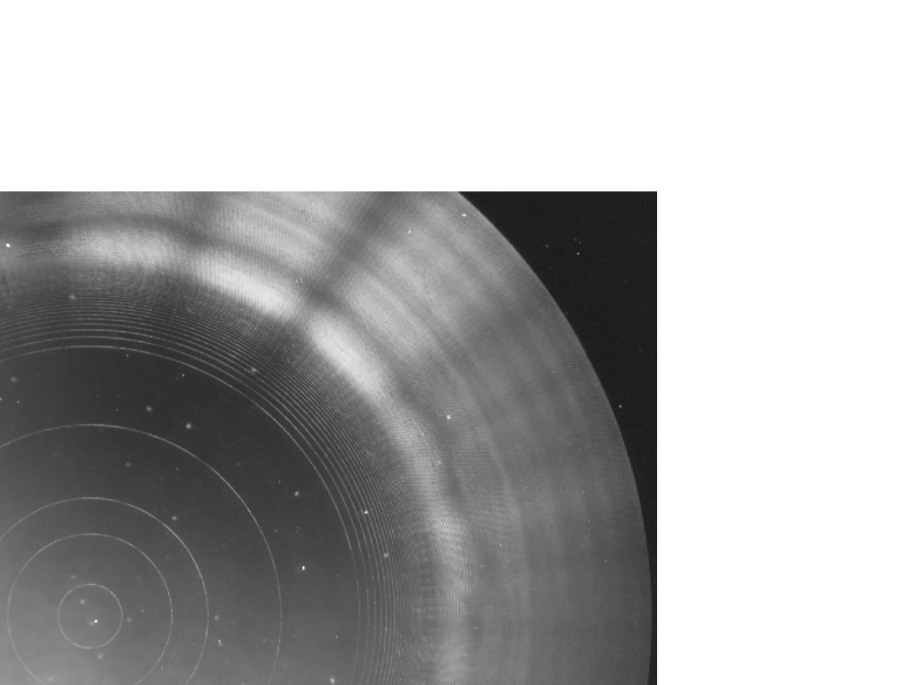
The dependence on the tilt azimuth is expressed in the use of the dot product . We have used this equation to predict how the off-axis affects the quality of the PSF. Fig. 11 presents the result of these predictions and compares them to laboratory images taken at different off-axis angles with the SRP only. The agreement between the simulations and the data over a fairly large field of view (20 ) is excellent and incidentally confirms the validity of the proposed approximations.
One sees that for angular separations up to 10 , the SRP produces an image with a pseudo-Airy disk. To better understand the off-axis PSF degradation by the SRP, Fig. 11 also plots the energy encircled within the pseudo-Airy disk for the relevant cases. Theoretical values of this quantity for a non-obstructed and a 30 % obstructed telescope like Subaru are respectively 85 % and 69 %. Because the SRP incidentally also reduces the size of the obscuration, simulations show that on-axis, the encircled energy is 72 %. It degrades by an acceptable 7 % for sources at a , and by an unfortunate 30 % at . Experimental images and measurements conform to these simulations, although the on-axis performance is reduced to 41 %. This lesser performance can be attributed to the absence of wavefront control in this experiment.
Over a sufficiently large (10 in diameter) field of view, the image quality appears very satisfactory, despite the absence of wavefront control, whithin which high contrast imaging is performed: an inverse SRP is not necessary in this observing mode. For non-coronagraphic ”wide field” observations, however, the SRP should be removed from the beam.
4.2 Off-axis imaging with a PIAA
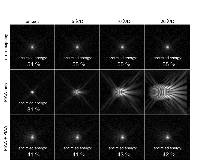
For an off-axis source, the pupil-remapping the PIAA performs introduces large aberrations to the wavefront, which translate into very unsually shaped PSFs. The matter is not new and has been extensively described by Guyon et al. (2005) in the case of a non-obstructed aperture. The novelty in the PIAA that will equip the SCExAO system is that it must accomodate the presence of a central obscuration, and as presented in Section 3.4, the PIAA lenses used in combination with the SRP manages to suppress it completely. This however requires a somewhat brutal remapping, with dramatic consequences on the PSF which finds itself pineapple-shaped at separations greater than 10 (cf. Fig. 12).
Fortunately, just like with any pupil remapping (Guyon & Roddier, 2002; Guyon, 2003), the aberrations the PIAA introduces can entirely be corrected using an exact copy of the PIAA, only plugged backwards, which restores the original pupil and provides wide field of view imaging capabilities. In practice, this so-called inverse PIAA is located in the pseudo pupil plane located after the occulting mask (cf. Fig. 7). While this idea of using an inverse system to recover wide-field of view capabilities after a PIAA coronagraph has often been mentioned in PIAA related publications (Guyon, 2003; Guyon et al., 2005; Martinache et al., 2006; Pluzhnik et al., 2006), this paper reports the first successful implementation of such an inverse system.
Figure 12 shows a series of off-axis images taken with and without the inverse PIAA and compares them to their equivalent without any remapping at all (except for the SRP). These images show that the inverse PIAA (bottom row) efficiently corrects the huge aberrations the PIAA introduces in the first place (middle row), and turns the pineapple-shaped off-axis images into more conventional Airy-like images, virtually identical to the ones the system produces with no beam apodization at all (top row).
Just as was done for the SRP (c.f. §4.1), Fig. 12 also shows the energy encircled within the pseudo-Airy disk of the PSFs (except for the pineapples). The theoretical value of this quantity for the Subaru Telescope pupil is 69 %. In the absence of remapping (first row), the experimentally measured encircled energy is 55 %. Despite the absence of wavefront control, the apodization by the PIAA manages to bring it a little over 80 % on-axis. With the inverse PIAA, the encircled energy stabilizes a little over 40 %, whatever the angular position of the source. This 20 % loss (relative to the initial 55 %) can be attributed to imperfection of the optics. Nevertheless, this result, achieved in the absence of wavefront control is remarkable: the obtention of an actual Airy disk after the inverse PIAA shows that the wavefront residuals RMS is better than . Observations in the near infrared and the deformable mirror on the actual SCExAO system should significatively improve this performance.
5 Conclusion
The Subaru Coronagraphic Extreme AO system is an instrument to be installed onto the Subaru Telescope, as an upgrade to the recently commissioned infrared camera HiCIAO (Hodapp et al., 2008). The SCExAO system offers the means to probe the innermost part of planetary systems by using technologies optimized for high contrast at small angular separation.
Because it is constrained by the fundamental limits of diffraction and the practical limits of actual telescopes, each high angular resolution imaging system is the result of a multi-variable optimization process: contrast versus angular separation versus field of view. While nothing fundamental prevents a PIAA-based coronagraph to achieve high contrast simultaneously with a small inner working angle and over a very wide field of view, practical limits like a large central obscuration and thick spider vanes, impose some level of specialization for high performance. The SRP+PIAA-based architecture of the SCExAO project was chosen to open a unique niche of high contrast with a small inner working angle for an 8-meter telescope. While focusing on a 10 -diameter field of view may seem restrictive, the recent results of other high angular resolution techniques working on a very small field of view, like aperture masking interferometry (Martinache et al., 2009) which SCExAO will also implement, show that such specialization pays off.
In that scope, this paper introduces two critical components of the system: a new design for the PIAA apodizer that accomodates the presence of a central obscuration and a compound phase plate that suppresses the spider vanes present in most modern telescope designs. The intensive tests conducted on these advanced optical components, at a wavelength three times shorter than nominal, demonstrate satisfactory performance despite the absence of wavefront control. We are now integrating these optics with the wavefront control system necessary to produce high contrast images.
The SCExAO system, in its first installment, is designed to provide high contrast imaging in the 1 to 4 separation range in imaging mode only (no spectroscopy). By using achromatic near-IR lenses for relay optics and a low dispersion material (CaF2) for the PIAA lenses, chromatic effects in SCExAO are mitigated. Polychromatic operation of SCExAO (for spectroscopy) has however not been explored at this point, and will likely require redesign of several components in the optical train (most importantly to compensate for the linear dependancy of the diffraction limit with wavelength in the focal plane). The effect of SCExAO residual chromatic effects on Simultaneous Differential Imaging (SDI) has also not been evaluated, but is believed to be manageable over the wide spectral band covered by each of the SDI filter. We note that SCExAO does not rely on SDI for differential detection: thanks to the high order SCExAO DM, coherence-based techniques to separate residual speckles from true sources (as demonstrated in Guyon et al. (2009)) will be the the primary speckle calibration mode.
References
- Abe et al. (2006) Abe L., Murakami N., Nishikawa J., Tamura M., 2006, A&A, 451, 363
- Aime & Soummer (2003) Aime C., Soummer R., 2003, in EAS Publications Series, edited by C. Aime, R. Soummer, vol. 8 of EAS Publications Series, 79–92
- Beuzit et al. (2006) Beuzit J.-L., Feldt M., Dohlen K., et al., 2006, The Messenger, 125, 29
- Biller et al. (2007) Biller B. A., Close L. M., Masciadri E., et al., 2007, ApJS, 173, 143
- Cavarroc et al. (2006) Cavarroc C., Boccaletti A., Baudoz P., Fusco T., Rouan D., 2006, A&A, 447, 397
- Guyon (2003) Guyon O., 2003, A&A, 404, 379
- Guyon (2005) Guyon O., 2005, ApJ, 629, 592
- Guyon et al. (2005) Guyon O., Pluzhnik E. A., Galicher R., Martinache F., Ridgway S. T., Woodruff R. A., 2005, ApJ, 622, 744
- Guyon et al. (2006) Guyon O., Pluzhnik E. A., Kuchner M. J., Collins B., Ridgway S. T., 2006, ApJS, 167, 81
- Guyon et al. (2009) Guyon O., Pluzhnik E. A., Martinache F., et al., 2009, PASP, submitted
- Guyon & Roddier (2002) Guyon O., Roddier F., 2002, A&A, 391, 379
- Hodapp et al. (2008) Hodapp K. W., Suzuki R., Tamura M., et al., 2008, in Society of Photo-Optical Instrumentation Engineers (SPIE) Conference Series, vol. 7014 of Society of Photo-Optical Instrumentation Engineers (SPIE) Conference Series
- Kalas et al. (2008) Kalas P., Graham J. R., Chiang E., et al., 2008, Science, 322, 1345
- Kasdin et al. (2005) Kasdin N. J., Vanderbei R. J., Littman M. G., Spergel D. N., 2005, Appl. Opt., 44, 1117
- Kasdin et al. (2003) Kasdin N. J., Vanderbei R. J., Spergel D. N., Littman M. G., 2003, ApJ, 582, 1147
- Kasper et al. (2007) Kasper M., Apai D., Janson M., Brandner W., 2007, A&A, 472, 321
- Labeyrie (1996) Labeyrie A., 1996, A&AS, 118, 517
- Lafrenière et al. (2007) Lafrenière D., Doyon R., Marois C., et al., 2007, ApJ, 670, 1367
- Lagrange et al. (2008) Lagrange A. ., Gratadour D., Chauvin G., et al., 2008, ArXiv e-prints
- Lyot (1939) Lyot B., 1939, MNRAS, 99, 580
- Macintosh et al. (2008) Macintosh B. A., Graham J. R., Palmer D. W., et al., 2008, in Society of Photo-Optical Instrumentation Engineers (SPIE) Conference Series, vol. 7015 of Society of Photo-Optical Instrumentation Engineers (SPIE) Conference Series
- Marois et al. (2008) Marois C., Macintosh B., Barman T., et al., 2008, ArXiv e-prints
- Martinache et al. (2006) Martinache F., Guyon O., Pluzhnik E. A., Galicher R., Ridgway S. T., 2006, ApJ, 639, 1129
- Martinache et al. (2009) Martinache F., Rojas-Ayala B., Ireland M. J., Lloyd J. P., Tuthill P. G., 2009, ApJ, 695, 1183
- Martinez et al. (2008) Martinez P., Boccaletti A., Kasper M., et al., 2008, A&A, 492, 289
- Pluzhnik et al. (2006) Pluzhnik E. A., Guyon O., Ridgway S. T., et al., 2006, ApJ, 644, 1246
- Racine et al. (1999) Racine R., Walker G. A. H., Nadeau D., Doyon R., Marois C., 1999, PASP, 111, 587
- Roddier & Roddier (1997) Roddier F., Roddier C., 1997, PASP, 109, 815
- Sivaramakrishnan & Lloyd (2005) Sivaramakrishnan A., Lloyd J. P., 2005, ApJ, 633, 528
- Soummer (2005) Soummer R., 2005, ApJ, 618, L161
- Soummer et al. (2003) Soummer R., Aime C., Falloon P. E., 2003, A&A, 397, 1161