Scattering of surface and volume spin waves in a magnonic crystal
Abstract
The operational characteristics of a magnonic crystal, which was fabricated as an array of shallow grooves etched on a surface of a magnetic film, were compared for magnetostatic surface spin waves and backward volume magnetostatic spin waves. In both cases the formation of rejection frequency bands was studied as a function of the grooves depth. It has been found that the rejection of the volume wave is considerably larger than of the surface one. The influences of the nonreciprocity of the surface spin waves as well as of the scattering of the lowest volume spin-wave mode into higher thickness volume modes on the rejection efficiency are discussed.
pacs:
75.50.Gg, 75.30.Ds, 75.40.GbMagnonic crystals, which are periodically structured magnetic materials, attract special attention in view of their applicability for both fundamental research on linear and nonlinear wave dynamics in artificial media, and for signal processing in the microwave frequency range MC review ; MC skyes ; MC MSSW ; Gubbiotti1 ; Gubbiotti2 ; Chumak_MC . An array of parallel grooves formed on the surface of a magnetic film seems to be one of the most effective methods to create a magnonic crystal MC review ; MC skyes ; MC MSSW ; Chumak_MC .
Thin magnetic films support propagation of different types of spin-waves depending on the angle between the wave propagation direction and the external magnetic field orientation. Backward volume magnetostatic spin wave (BVMSW) and magnetostatic surface spin wave (MSSW) configurations are characterized by parallel and perpendicular wave propagation relative to the magnetizing field applied in the film plane Damon-Eshbach . Both types of spin waves can be used in the magnonic crystal. As a whole, MSSW devices offer more benefits for microwave applications in comparison to BVMSW devices, in particular, because of more efficient excitation and reception by means of microwave antennas. Furthermore, MSSW devices possess a noteworthy specificity: they are nonreciprocal, which means that waves propagating in opposite directions in the film plane are localized at different film surfaces. They also couple differently to surface scatterers (for example to microstrip antennas) which results in nonreciprocal excitation of these waves PRB_Kostylev . Thus, the investigation of propagation of magnetostatic surface spin waves in an artificial magnonic crystal establishes the general problem of propagation and scattering of nonreciprocal waves in structured media.
In our recent paper Chumak_MC we presented results on scattering of BVMSW from a quasi-one-dimensional periodic structure of grooves in a film surface. The main advantage of BVMSW-based magnonic crystals was the excellent spin-wave signal rejection ratio of more than 30 dB. In contrast to MSSW, BVMSW are reciprocal waves. In this work we compare the operational characteristics of MSSW-based magnonic crystals with characteristics of BVMSW-based magnonic crystals.
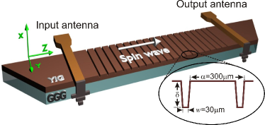
To fabricate magnonic crystals, a m thick yttrium iron garnet (YIG) film was used. Photolithographic patterning followed by hot orthophosphoric acid etching was used to form the grooves. The etch mask had 20 parallel lines of width m spaced m away from each other, so that the lattice constant is m Chumak_MC (see Fig. 1). The grooves depth was varied from 100 nm to m by controlling the etching time and was measured using a surface profilometer. Two microstrip antennas placed 8 mm apart on each side of the grooved area were used to excite and receive spin waves as shown in Fig. 1. A bias magnetic field of A/m was applied in the plane of the YIG film, either along or perpendicular to the -axis depending on the type of spin waves under investigation. A microwave network analyzer was used to measure transmission characteristics of these magnonic crystals.
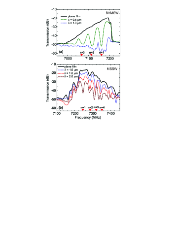
The experimental BVMSW transmission characteristics for the unstructured film as well as for the gratings with and 1000 nm are shown in Fig. 2(a). In this case the bias magnetic field was applied along the -axis (see Fig. 1). The BVMSW transmission characteristics for the unstructured film is limited from above by the ferromagnetic resonance frequency and from below by a drop in the microwave antenna excitation efficiency for shorter wavelengths. The insertion loss is determined by the energy transformation efficiency by the input and the output antennas and by the spatial decay of spin waves. As can be seen in Fig. 2(a) grooves as shallow as nm result in the appearance of a set of pronounced rejection bands (or transmission gaps), where spin-wave transmission is highly reduced. The onset of the rejection bands corresponds to a groove depth of 100 nm Chumak_MC . For m the insertion loss in the whole spin-wave band is so pronounced that almost no spin-wave propagation is observed (see Fig. 2(a)). Triangles in the figure show theoretically calculated positions of rejection bands, with denoting the number of respective Bragg reflection band.
The measured MSSW transmission characteristics for the unstructured film as well as for the gratings with =1, 1.6, and 2 m are shown in Fig. 2(b). In this case bias magnetic field was applied perpendicular to the spin-wave propagation direction (i.e. along the -axis in Fig. 1). The MSSW transmission characteristics for the unstructured film is limited by the ferromagnetic resonance frequency from below and by the microwave antenna excitation efficiency from above, thus it looks like a mirror reflection to the BVMSW transmission characteristics. Several rejection bands in the transmission characteristics for the unstructured YIG film can be seen in Fig. 2(b). These bands are formed due to “exchange gaps” in the MSSW spectrum. Their origin is hybridization of MSSW with higher-order standing-wave resonances across the film thickness Kalinikos86 ; PRL_restoration . Positions and depths of these rejection bands are determined by the film thickness and conditions for magnetization pinning at the film surface. Obviously, the potential formation of exchange gaps is a drawback of the MSSW configuration.
Upon formation of the groove arrays on the surface of the YIG film new rejection bands appear (see Fig. 2(b)). Some of them overlap the exchange gaps. A groove depth =0.5 m (not shown in Fig. 2(b)) results only in a slight modification of the MSSW transmission, while for BVMSW the same structure shows rejection bands of approximately 30 dB in depth (see Fig. 2(a)). An increase in to 1 m results in the appearance of pronounced rejection bands (while for BVMSWs one sees complete rejection for this groove depth). Further increase in results in an increase in the rejection efficiency and in insertion loss in the pass bands. Thus, the operational characteristics of magnonic crystals with =2.0 m is completely unsatisfactory.
Triangles in Fig. 2(b) show positions of the rejection bands calculated based on Bragg’s law. Apart from the formation of rejection bands two more effects occur. These effects are weak, but noticeable. First, with increase in the rejection bands are slightly shifted towards lower frequencies for the MSSW-based crystal. A similar shift but towards higher frequencies was previously shown experimentally and theoretically for the BVMSW geometry Chumak_MC . In both cases this shift corresponds to a slight decrease in wave vectors of the waves, for which the Bragg condition is fulfilled. Another effect, which seems to take place, is the increase in the depth of exchange gaps. We suppose that it is caused by chemical processing of the film surface at the place of the grooves etching . Chemical etching increases magnetization pinning at the film surface which leads to an increase in rejection band depth. Simultaneously the positions of these gaps are also slightly shifted because the film thickness changes at the groove positions.
As seen in Fig. 2, the groove depth determines the transmission characteristics of the fabricated magnonic crystals for both types of spin waves. In order to investigate this effect, the insertion loss for the first-order rejection band and the parasitic loss in the first pass band for the BVMSW and MSSW-based magnonic crystals are plotted in Fig. 3 as functions of the groove depth . The central frequency for the first-order gap for BVMSW is 7160 MHz, and it is 7245 MHz for MSSW.
It can be seen from Fig. 3 that the behavior of the operational characteristics for MSSW and BVMSW-based crystals is qualitatively similar: with increase in the groove depth the loss in the rejection bands increases as well as the loss in the pass bands, but the latter effect is smaller. However, one sees that for MSSW-based magnonic crystals the increase in loss is weaker, or, in other words, MSSW is not as sensible to inhomogeneities at the film surface as BVMSW. For example, for a 5.5 m-thick YIG film and for the BVMSW configuration the rejection efficiency reaches 30 dB for m, while for the MSSW configuration this groove depth results in a rejection about six hundred times smaller (2 dB).
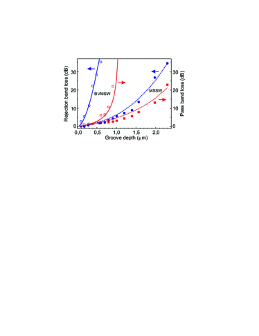
The dependencies shown in Fig. 3 can be approximated by the simple model we previously presented in Ref. Chumak_MC . This model is based on the analogy of a spin-wave waveguide with a microwave transmission line. In the framework of this theory it was assumed that spin-wave reflection is caused by periodical variation of the effective characteristic impedance of the spin-wave waveguide due to the periodic variation of the YIG-film thickness in the grooved area. As it is seen from Fig. 3 the theory agrees well with the experimental data for the BVMSW-based magnonic crystal. However, in order to achieve the qualitative agreement with the experimental data we had to multiply the theoretical reflection coefficient with an empirical coefficient Chumak_MC . For MSSW one also obtains good qualitative agreement with the experiment, however to obtain quantitative agreement a much smaller value for the empirical coefficient is necessary. This phenomenological theory does not reveal physical mechanisms underlying the drastic difference in the spin-wave scattering efficiencies for these two types of waves. However, it suggests that the behavior of both types of waves is qualitatively the same. In order to explain the difference in rejection one has to explain the factor 12 in the strength of scattering from a single groove.
The problem of scattering of spin waves from inhomogeneities can be posed as a conventional integral-equation formulation of the scattering problems scattering . In the case of BVMSW Chumak_MC the integral equation is scalar, but for MSSW it is a vector one and makes use of the whole tensorial Green’s function of excitation of spin waves by an external source PRB_Kostylev . Both types of spin waves possess an in-plane and an out-of-plane component of the dipole field. However, only the out-of-plane component of the dipole field exerts a torque on the magnetization vector in the BVMSW case, while for MSSWs both field components contribute to the torque. The vector character of the integral equation for MSSW reflects the latter fact. MSSW are non-reciprocal waves, which is also reflected in the Green’s function of excitation PRB_Kostylev . However, solving the scattering problem for the periodical potential of grooves in the first Born approximation scattering gives a result which is of the same form as was previously found for BVMSWs in Ref. MC_JAP . No effect of nonreciprocity is seen in the expressions derived for MSSW. Furthermore, in the first Born approximation the amplitude of the wave transmitted through the groove structure is of the same order of magnitude for both BVMSW and MSSW. This result is in clear contradiction with the experimental data.
Thus, accurate numerical modeling of both BVMSW and MSSW cases (which is out of the scope of this paper) is necessary to explain the observed large difference in the depths of rejection bands for these two cases. In contrast to Ref. scattering ; PRB_Kostylev ; MC_JAP , this model should be two-dimensional, i.e. it should include dynamic-field variations across the film thickness, since one of the possible contributions to this difference is coupling of the incident BVMSW to higher-order BVMSW thickness modes in the grooved area. The latter is seen in the thickness-resolved integral equation formulation of the problem of BVMSW scattering. More efficient transfer of energy of the incident lowest-order mode of BVMSW into the higher-order modes when the condition for the standing-wave resonances (Bragg’s law) in the grooved area is met, can be responsible for the increased depths of the rejection bands in the BVMSW case.
In conclusion, we have experimentally demonstrated the strong difference of operational characteristics of chemically etched one-dimensional magnonic crystals for cases when reciprocal backward volume magnetostatic spin waves or nonreciprocal magnetostatic surface spin waves were used as signal carriers. It has been shown that even small regular distortions of the surface of a magnetic film result in the appearance of pronounced rejection bands in the BVMSW frequency spectrum. At the same time such distortions only slightly affect the propagation of the surface spin wave. The scattering of the lowest BVMSW mode to the higher-order thickness modes is assumed as a possible mechanism of the observed effective rejection of this wave.
Financial support by the DFG SE 1771/1-1, Australian Research Council, and the University of Western Australia is acknowledged.
References
- (1) K. W. Reed, J. M. Owens, and R. L. Carter, Circ. Syst. Signal Process. 4, 157 (1985).
- (2) C. G. Skyes, J. D. Adam, and J. H. Collins, Appl. Phys. Lett. 29, 388 (1976).
- (3) J. P. Parekh and H. S. Tuan, Appl. Phys. Lett. 30, 667 (1977).
- (4) M. Kostylev, P. Schrader, R. L. Stamps, G. Gubbiotti, G. Carlotti, A. O. Adeyeye, S. Goolaup, and N. Singh, Appl. Phys. Lett. 92, 132504 (2008).
- (5) G. Gubbiotti, S. Tacchi, G. Carlotti, N. Singh, S. Goolaup, A. O. Adeyeye, and M. Kostylev, Appl. Phys. Lett. 90, 092503 (2007).
- (6) A. V. Chumak, A. A. Serga, B. Hillebrands, and M. P. Kostylev, Appl. Phys. Lett. 93, 022508 (2008).
- (7) R.W. Damon and J.R. Eshbach, Phys. Chem. of Solids, 19, 308 (1961).
- (8) T. Schneider, M. P. Kostylev, A. A. Serga, T. Neumann, and B. Hillebrands Phys. Rev. B 77, 214411 (2008)
- (9) B. A. Kalinikos and A. N. Slavin, J. Phys. C 19, 7013 (1986).
- (10) A. A. Serga, A. V. Chumak, A. Andre, G. A. Melkov, A. N. Slavin, S. O. Demokritov, and B. Hillebrands, Phys. Rev. Lett. 99, 227202 (2007).
- (11) J. Basterfield, J. Phys. D: Appl. Phys. 2, 1159 (1969).
- (12) M. P. Kostylev, A. A. Serga, T. Schneider, T. Neumann, B. Leven, B. Hillebrands, and R. L. Stamps, Phys. Rev. B 76, 184419 (2007).
- (13) A. V. Chumak, A. A. Serga, S. Wolff, B. Hillebrands, and M. P. Kostylev, J. Appl. Phys. 105 (6) (2009) in press.