A Large TPC Prototype with MPGD Readout: Status and Plans
Abstract
The use of a TPC in future collider experiments needs significant research and development. Within the EUDET program an infrastructure has been designed and built to allow the efficient testing of TPC prototypes under realistic conditions. The infrastructure consists of a test beam facility, located at DESY Hamburg, and a multi-purpose TPC field cage.
1 Introduction
Time projection chambers have been successfully used in many experiments at colliding beam facilities. The latest example is the ALICE TPC, which has very recently been commissioned, and which is scheduled to start recording collisions as soon as the LHC commences operation. The next generation of TPCs is now planned for future collider projects, for example the international linear collider. These future chambers need to deliver excellent precision, need to operate stable and reliable, and will need to operate in a high luminocity collider where many bunch collisions take place during one readout cycle of a TPC. An important criterion in addition is the amount of material presented by the detector, which should be minimal.
A traditional TPC based on a wire chamber readout does to meet all requirements. Alternatives solutions have been studied over the past few years, which are based on readout systems using micro pattern gas detectors, e.g. Gas Electron Multipliers (GEM) or Micro Mesh Gas Amplifiers (MicroMegas). Both promise to deliver a potentially better spatial resolution, due to the smaller intrinsic size of the gas amplification structures, they offer stable and simple operation, and they promise in addition to operate even in a multi-bunch crossing scenario like the ILC since they naturally suppress the amount of ions back-drifting into the TPC volume.
2 The EUDET TPC facility
The LC-TPC collaboration [1] has been formed to develop the case for a TPC at the linear collider. In the past the feasibility of a MPGD based TPC has been successfully demonstrated, both for GEM and MicroMegas readout, using small scale prototypes. The next step now is a larger system test of a TPC with beam, with a significant number of readout channels, to prove that the resolution and overall performance requirements of a TPC at the ILC can be met.
The EUDET project [2] is developing a test infrastructure, which is well suited for the needs of the LC-TPC collaboration. It consists of a beam line, located at the electron test beam facility at DESY Hamburg, equipped with a 1 T superconducting magnet, and needed auxiliary equipment. It also includes a multi-purpose field cage built to be used with different readout modules for a TPC. The field cage is designed such that it fits into the magnet, and can optimally exploit the EUDET facility.
The LC-TPC collaboration is the first major user of this facility. It is equipping the field cage with two types of readout systems (GEM and MicroMegas), and will test several different readout electronics systems with the same chamber. The collaboration is also contributing significantly to the commissioning and further development of the EUDET infrastructure.
3 Status of the superconducting Magnet
The EUDET facility is equipped with a superconducting magnet, which can provide a solenoidal field of around 1.0 T. The magnet is on lease from KEK, where it has been developed for a balloon based experiment. It has a number of special features, which make it particularly well suited for the EUDET facility. Its construction has been optimized for low mass. The amount of material in the walls of the magnet is less than of a radiation length per side, which makes it possible that an electron beam can penetrate the walls of the magnet and still be used for a test inside the magnet. The magnet is also designed so that it can be moved while cold, so that the magnet as a whole can be placed on a movable stage in the beam, and the complete active area of the chamber inside the magnet can be scanned with beam. Due to the requirements of low mass, the magnet is not equipped with an iron return yoke. This has a significant impact on the field quality inside the magnet.
The magnet was delivered to DESY in 2007, and installed and commissioned in 2008. First experiment using the magnet were conducted at the end of 2008.
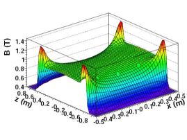
An important step was the precise measurement of the magnetic field map of the magnet. Using a system of hall probes mounted on a precision arm, several thousand points were recorded inside the magnet volume. The resulting field map was parametrized based on a model of the expected field shape [3]. In Figure 1 the result of the parametrization is shown. The variations of the field are as large as 0.2 T. Point by point, the largest deviations between the model and measurements are as much as 10 G, or . This is somewhat worse than the goal of a few times , but still good enough for most of the planned measurements.
At the moment the magnet is installed in a fixed position in the beam line at DESY. In the first half of 2009 the area will be equipped with a remote controllable table, which can move the magnet vertically, horizontally through the beam, and also rotate the magnet relative to the beam by up to degree.
4 Field Cage
4.1 Overall program goals
Testing different readout mechanisms of a TPC under comparable conditions require that a multi-purpose TPC is built, which can equally well operate with different readout systems. The goal of the LC-TPC collaboration together with the EUDET program has been to develop such a multi purpose infrastructure. A central part of this is a field cage, which fits inside the magnet described in the previous section, and which can be equipped with a wide range of different readout modules.
4.2 Field Cage Construction
The field cage is a light-weight cylindrical structure. Its main parameters are summarized in table 1.
Parameter value Outer Diameter (cm) 77 Inner active Diameter (cm) 72 Length (cm) 61 Drift Length (cm) 58 Wall thickness (% X0) 1.3 Cathode Al disk
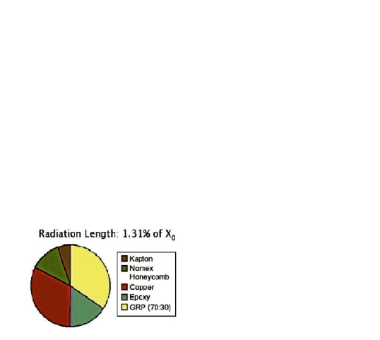
The walls are a light weight composite structure, build around a core of Nomex with thin skins of glas-fibre reinforced epoxy on either side. Electrically Kapton sheets provide both insulation and - on the inside - a pattern of field shaping strips. Overall one wall of the TPC corresponds to of a radiation length (see Figure 2). The largest contribution comes from the epoxy/ glas fibre system and from the copper used for the field shaping strips and a grounding layer on the outside [4].
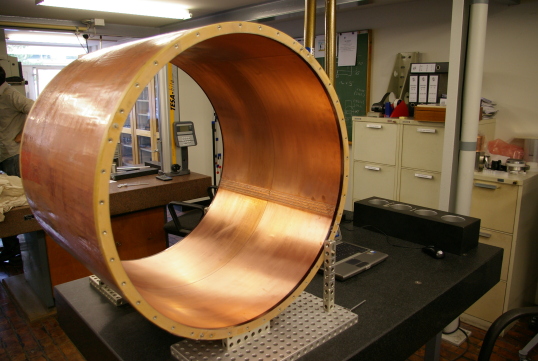
The two ends of the cylinder are terminated with flanges, built from a high density foam. The end plate and the cathode plate are attached to these flanges with a ring of M6 stainless steel screws. An O-ring ensures the necessary gas tightness. The cathode is a disk of aluminum copper coated on the inside. It is supported at three points from a lid which is used to close off the field cage. The three point support is designed in a way that the cathode can be aligned parallel to the field strips, to ensure an optimal field quality inside the field cage.
The building of the field cage was done by an outside company over a purpose built mandrel. A careful survey of the field cage after the construction showed that the dimensions of the system were within mm of the specified parameters. The two end flanges are parallel to each other to better than mrad. The flanges are however at a slight angle relative to the field cage of mrad. This corresponds to a relative displacement of the axes of the two end plates to each other of mm, which is outside the tolerance of mm. The impact of this on the ultimate precision with which the electric field in the chamber is know, is under evaluation.
A picture of the finished field cage is shown in figure 3.
4.3 TPC End Plate
The readout modules of the TPC are help by an aluminum end plate, which is described in more detail elsewhere. In the first iteration the end plate has been built from aluminum, with openings for seven readout modules. The readout modules are arranged on a circle which corresponds to the expected circle in the final TPC at the ILC. Frames machined from Aluminum are pulled against this end plate from the inside of the TPC, so that they cover the complete area, without any dead area. The readout modules are then built up on these frames. A system of dowel pins ensures that the frames are precisely positioned relative to the end plate.
A major challenge of the TPC developments for the linear collider is the minimization of material in the end plate. The Aluminum model clearly is not optimized in this direction, but serves as a first and stable platform to develop and test readout modules. It is planned to replace the end plate by a lighter one in a second step. The design of this lighter end plate is not yet finished. Possibly it will be based on Carbon-fibre technology, or another advanced composite material system. A reduction of the material in the endplate of at least a factor of two is envisioned.
4.4 Commissioning of the TPC
After delivery of all parts the TPC was commissioned during the fall of 2008. After initial assembly and gas tightness and high voltage tests, the chamber was equipped with a single sensitive module, based on the MicroMegas technology. More details about the readout module may be found in [5]. No major problems were encountered during the commissioning phase. The field cage stood the high voltage without problems. The gas tightness of the system was achieved with minimal problems.
5 Conclusion
A light weight field cage for a TPC has been designed and built. It is equipped with a readout system which can support up to seven readout modules. A total material equivalent of of a radiation length has been achieved for one wall of the field cage. Excellent mechanical properties were obtained. Equipped with an aluminum end plate the chamber was commissioned in the fall of 2008 without major problems. It will be operated at the DESY electron test beam for the next years equipped with different readout modules based on a range of different technologies.
6 Acknowledgments
The construction and building of the TPC infrastructure is the result of a collaboration of many different people, whose support and help in writing this report is acknowledged.
References
- [1] see http://www.lctpc.org
- [2] see http://www.eudet.org
- [3] C. Grefe, “Magnetic field map for a large TPC prototype,”, DESY-THESIS-2008-052
- [4] P. Schade et.al., ”Status and Plans of the Large TPC Prototype for the ILC”, EUDET-Memo-2007-37
- [5] P. Colas, in these proceedings