Comment on “Band structure engineering of graphene by strain: First-principles calculations”
Abstract
In their first-principles calculations of the electronic band structure of graphene under uniaxial strain, Gui, Li, and Zhong [Phys. Rev. B 78, 075435 (2008)] have found opening of band gaps at the Fermi level. This finding is in conflict with the tight-binding description of graphene which is closed gap for small strains. In this Comment, we present first-principles calculations which refute the claim that strain opens band gaps in graphene.
pacs:
73.22.f, 73.61.Wp, 72.80.RjGui et al. Gui et al. (2008) have used first-principles calculations to investigate the effect of planar strain on the electronic band structure of graphene, and have found opening of band gaps at the Fermi level resulting from arbitrarily small uniaxial strains, applied parallel or perpendicular to the C-C bonds. However, tight-binding (TB) model on the honeycomb lattice with different nearest-neighbor hoppings in the three directions has been rigorously shown to be closed gap as long as the hoppings satisfy the triangle inequality. Hasegawa et al. (2006); Wunsch et al. (2008) The closed-gap TB model, which contains zero modes, has been further developed recently to include the effects of magnetic fields Goerbig et al. (2008); Dietl et al. (2008) and corrugations in graphene. Wehling et al. (2008) The discrepancy between the first-principles calculations of Ref. 1 and TB model has already been discussed Pereira et al. (2009) but the reason has not been identified. One suggested explanation Pereira et al. (2009) is that this band gap opening is an artifact of density-functional theory (DFT) calculations. However, the possibility that the nearest-neighbor TB model is an incomplete description has not been ruled out. Pereira et al. (2009); Kishigi et al. (2008)
We remind that the DFT methods essentially solve single-particle Schrödinger equations (Kohn-Sham equations) for effective potentials based on the underlying lattice, and the TB model solves the same problem in a simplified approximation. Therefore, it seems unlikely that qualitative differences exist between DFT and TB band structures. We also see indications of possible error in Ref. 1. First, Figs. 3(c) and 5(c) of Ref. 1 show a peculiar peak whose underlying cause is not explained. Second, an energy gap is incorrectly ascribed to the TB band structure which is then plotted in Fig. 4 of Ref. 1 with large symbols that hide the important band crossing.
In this Comment, we check directly the first-principles calculations of Ref. 1 by one of the available DFT codes. We used the Quantum-ESPRESSO Giannozzi et al. package based on the pseudopotential plane-wave method. We obtained the pseudopotential C.pw91-van_ak.UPF also from Ref. 9 and used a kinetic-energy cutoff of 40 Ry, a Monkhorst-Pack -point mesh of , and a vacuum separation of Å along the axis. We chose these parameters as close as possible to those of Ref. 1 for a more meaningful comparison. vasp
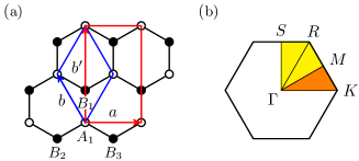
First, we determined the equilibrium lattice constant of graphene in the absence of strain. We found a value of Å, defined in Fig. 1(a), which is not significantly different from the 2.4669 Å found in Ref. 1. We then made calculations on graphene under uniaxial strain for two special cases, for which Ref. 1 has found maximum values for band-gap openings. These two cases are (i) 12.2% strain applied parallel to the C-C bond, i.e, along direction in Fig. 1(a), and (ii) 7.3% strain applied perpendicular to the C-C bond. For comparison, recent experimental studies of strain in graphene have applied strains of up to 1.3% by stretching or bending a flexible substrate, on which graphene was deposited, and have measured them by Raman spectroscopy. Ni et al. (2008, 2009); Mohiuddin et al. (2009) Relatively large strains used in our calculations are more convenient to demonstrate the effects but the conclusions apply equally to smaller strains. The uniaxial strain deforms the triangular lattice of graphene into centered rectangular lattice, shown in Fig. 1. Thus for case (i), is fixed at 12.2% larger value than its unstrained value of , and the value of is varied until the stress in the direction becomes vanishingly small. Of course, for each choice of , the positions of the atoms must be relaxed until interatomic forces become sufficiently small. We found Poisson’s ratio to be for case (i). A similar procedure is used for case (ii), with fixing at a value of 7.3% larger than the original value, and then optimizing . Here Poisson’s ratio was found .
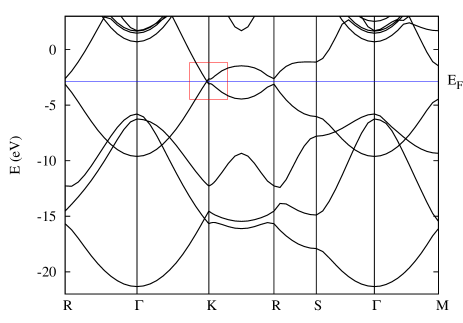
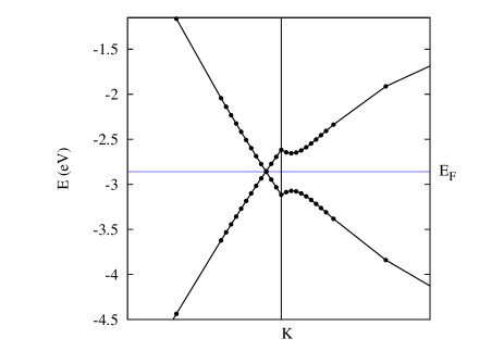
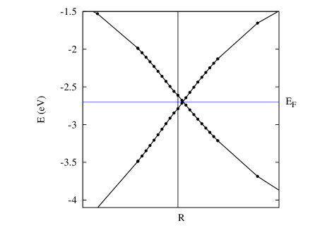
The band structure we obtained for case (i) along the -point path of Fig. 1(b) is shown in the top panel of Fig. 2, with its important portion magnified in the bottom panel. In the band plots, we used a regular -point mesh of 60 points for the entire path and refined it by the addition of 20 extra points as shown in the magnified part. The existence of a contact is clearly seen between the conduction and valence bands near on the line of the Brillouin zone. The displacement of the Dirac cone along toward is in agreement with the TB description of Ref. 2. Our Fig. 2 is to be compared with Fig. 3 of Ref. 1, where they give a value of 0.486 eV for the band gap. In our calculation, we find a value of 0.498 eV for the energy splittings at and in the top panel of Fig. 2, which is probably what is taken, in this case, as the band gap by Ref. 1, having missed the nearby band crossing.
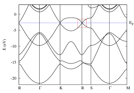
The band structure corresponding to case (ii) is shown in Fig. 3, and must be compared with Fig. 5 of Ref. 1. The main difference with case (i) is that here the band crossing occurs near the point on the line. This is equivalent to a shift of the Dirac point along the line away from , i.e., in the opposite direction to that of case (i). In Ref. 1 a value of 0.170 eV is given for the band gap for this case. We found a value of 0.178 eV for the energy splittings at and , which is, as in the other case, close to the band gap given in Ref. 1.
In conclusion, our first-principles calculations establish that graphene under uniaxial strain is gapless in agreement with the tight-binding model. Our numerical values and the general shape of band structures are quite similar to those found in Ref. 1. However, accidental degeneracies in the band structure have been disregarded in Ref. 1, and this has resulted in the appearance of spurious maxima in band gaps as a function of strain.
ACKNOWLEDGMENTS
M.F. acknowledges funding from the Iranian Nanotechnology Inititiative, and H.R.-T. from the Iran National Science Foundation.
References
- Gui et al. (2008) G. Gui, J. Li, and J. Zhong, Phys. Rev. B 78, 075435 (2008).
- Hasegawa et al. (2006) Y. Hasegawa, R. Konno, H. Nakano, and M. Kohmoto, Phys. Rev. B 74, 033413 (2006).
- Wunsch et al. (2008) B. Wunsch, F. Guinea, and F. Sols, New J. Phys. 10, 103027 (2008).
- Goerbig et al. (2008) M. O. Goerbig, J.-N. Fuchs, G. Montambaux, and F. Piéchon, Phys. Rev. B 78, 045415 (2008).
- Dietl et al. (2008) P. Dietl, F. Piéchon, and G. Montambaux, Phys. Rev. Lett. 100, 236405 (2008).
- Wehling et al. (2008) T. O. Wehling, A. V. Balatsky, A. M. Tsvelik, M. I. Katsnelson, and A. I. Lichtenstein, EPL 84, 17003 (2008).
- Pereira et al. (2009) V. M. Pereira, A. H. Castro Neto, and N. M. R. Peres, Phys. Rev. B 80, 045401 (2009); arXiv:0811.4396.
- Kishigi et al. (2008) K. Kishigi, R. Takeda, and Y. Hasegawa, J. Phys.: Conf. Ser. 132, 012005 (2008).
- (9) P. Giannozzi et al., J. Phys.: Condens. Matter 21, 395502 (2009).
- (10) We note that the vasp code was used in Ref. 1. However, with correct usage and interpretation, we expect any standard DFT code to produce the same gapless spectrum that we obtained.
- Ni et al. (2008) Z. H. Ni, T. Yu, Y. H. Lu, Y. Y. Wang, Y. P. Feng, and Z. X. Shen, ACS Nano 2, 1033 (2008).
- Ni et al. (2009) After submission of our manuscript we became aware of a correction article to Ref. 11 which addresses a similar issue as our Comment: Z. H. Ni, T. Yu, Y. H. Lu, Y. Y. Wang, Y. P. Feng, and Z. X. Shen, ACS Nano 3, 483 (2009).
- Mohiuddin et al. (2009) T. M. G. Mohiuddin, A. Lombardo, R. R. Nair, A. Bonetti, G. Savini, R. Jalil, N. Bonini, D. M. Basko, C. Galiotis, N. Marzari, K. S. Novoselov, A. K. Geim, A. C. Ferrari, Phys. Rev. B 79, 205433 (2009).