Galactic Warps in Triaxial Halos
Abstract
We study the behaviors of galactic disks in triaxial halos both numerically and analytically to see if warps can be excited and sustained in triaxial potentials. We consider the following two scenarios: 1) galactic disks that are initially tilted relative to the equatorial plane of the halo (for a pedagogical purpose), and 2) tilted infall of dark matter relative to the equatorial plane of the disk and the halo. With numerical simulations of 100,000 disk particles in a fixed halo potential, we find that in triaxial halos, warps can be excited and sustained just as in spherical or axisymmetric halos but they show some oscillatory behaviors and even can be transformed to a polar-ring system if the halo has a prolate-like triaxiality. The non-axisymmetric component of the halo causes the disk to nutate, and the differential nutation between the inner and outer parts of the disk generally makes the magnitude of the warp slightly diminish and fluctuate. We also find that warps are relatively weaker in oblate and oblate-like triaxial halos, and since these halos are the halo configurations of disk galaxies inferred by cosmological simulations, our results are consistent with the fact that most of the observed warps are quite weak. We derive approximate formulae for the torques exerted on the disk by the triaxial halo and the dark matter torus, and with these formulae we successfully describe the behaviors of the disks in our simulations. The techniques used in deriving these formulae could be applied for realistic halos with more complex structures.
1 INTRODUCTION
The outer parts of the disks in most spiral galaxies, even in isolated ones, are warped (Ann & Park 2006 and references therein), and this implies that the warps must be either long-lived or be repeatedly excited. Early proposals for the excitation mechanism of disk warps include the intergalactic gas flow past the disk (Kahn & Woltjer 1959), tidal distortion due to the Magellanic Clouds (Elwert & Hablick 1965), and the free mode of oscillation of a disk (Lynden-Bell 1965).
Extending the work by Lynden-Bell, Hunter and Toomre (1969) studied the warp in terms of discrete modes of oscillation of an isolated, thin, self-gravitating disk and found that a long-lived warp can correspond to a simple discrete mode only when the disk has an unrealistically sharp edge. Later, Sparke and Casertano (1988) showed that self-gravitating disks even with realistic density profiles may have long-lived discrete modes if the disk is embedded in the fixed potential of an axisymmetric halo (such modes are called the modified-tilt mode).
Dekel & Shlosman (1983) and Toomre (1983) suggested a misalignment between the disk and the non-spherical halo as the cause of the warp, and Dubinski & Kuijken (1995) and Ideta et al. (2000), among others, performed simulations for such configuration. With simulations of tilted disks in fixed, axisymmetric halos, Ideta et al. found that prolate halos could sustain galactic warps while the warping in oblate halos continues to wind up and disappears fairly quickly.
However, dynamical friction between the disk and halo may cause the warp to disperse within timescales much shorter than a Hubble time (Nelson and Tremaine 1995). Numerical studies employing live halos (Dubinski & Kuijken 1995; Binney, Jiang, & Dutta 1998), which can properly consider the reaction of the halo to the disk, confirmed that dynamical friction may play an important role in the disappearance of galactic warps on a time scale shorter than a Hubble time. Thus a successful scenario for the warp should not give rise to significant dynamical friction. Plausible scenarios that do not suffer the damping problem include the reorientation of a massive galactic halo by the cosmic infall (Ostriker & Binney 1989; Jiang & Binney 1999; Shen & Sellwood 2006) and the external torque produced in the disk by the accretion of the intergalactic medium (Revaz & Pfenninger 2001; Lopez-Corredoira et al. 2002).
Shen & Sellwood (2006) performed simulations of an idealized form of cosmic infall on to a disk galaxy and obtained warps that persist for a few Gyr. They found that the damping from the live halo is very weak compared to that in initially tilted disk scenarios, and attributed the difference to the facts that 1) the source of the torque in their model resides in the outer halo only, 2) the precession rate of their disk is very low, and 3) the effect of the torque in their model kicks in gradually.
It appears that the model by Shen & Sellwood (2006) is a highly feasible way of exciting and sustaining a warp, because their warps closely resemble those observed and do not significantly suffer the damping problem. But their halo is modeled to be spherical, wherease many numerical studies on the shape of the dark matter halos anticipate that the triaxiality of the dark matter halos is not negligible (Jing & Suto 2002; Bailin & Steinmetz 2005; Allgood et al. 2007, among others). Thus it is worth checking if the results of the cosmic infall scenario are significantly altered when the halo is modeled to be axisymmetric or triaxial. Furthermore, as the triaxiality of the halo exerts a torque that periodically increases and decreases the inclination angle of the tilted disk (see §2), the initially tilted disk scenario deserves a revisit to see if the extra torque by the halo triaxiality can diminish the effect of the damping.
For these reasons, in the present paper we study the evolution of the self-gravitating disks in axisymmetric and triaxial halos for two scenarios: 1) initially tilted disks in triaxial halos and 2) tilted cosmic infall in axisymmetric and triaxial halos. As discussed above, the first scenario does not appear to be a plausible mechanism for real warps, but we first study this scenario in detail to understand the influence of the triaxial potential alone to the disk. After successfully describing it with simulations and some analytical formulae, we then analyze the behaviour of the warp in the second scenario.
As a first step, the halos in the present paper are fixed, and this will enable us to concentrate on studying how the axisymmetry and/or triaxiaility of the halo alters the evolution of the warp compared to the spherical or axisymmetric cases. As a subsequent study to the present one, we will examine the disks in “live” axisymmetric and triaxial halos, which can properly treat the effect of dynamical friction between the disk and the halo.
Note that the aim of the present study is to understand the fundamental dynamics between the disk and the axisymmetric or triaxial halo for the above two scenarios, rather than to find the conditions that best reproduce the various observed characteristics of the warp. Still, we will briefly compare our simulations and observed warps in §6.
Warps are generally more extended in radio observations of gas than in optical observations of stars. However, in the present study, we only consider the stellar component of the disk to avoid the model complexity and computing cost involved with the consideration of the hydrodynamic (and even magnetohydrodynamic) effects. Thus the warps in our simulations are to be compared to the inner parts of the observed, extended warps.
We describe the models and the numerical method in §2, and discuss some theoretical backgrounds necessary for the analyses of our simulations in §3. The results and analyses of our simulations for initially tilted disks are presented in §4, and those for the tilted cosmic infall scenario are presented in §5. We summarize and discuss our results in §6.
2 MODELS
For the simulations presented here, we use a parallel version of the tree N-body code named GADGET (Springel, Yoshida, and White 2001). The code can calculate hydrodynamic forces using the smoothed particle hydrodynamics (SPH) technique, but we only consider gravitational forces for the present work, i.e. we do not consider the effects of gas component in the disk. Gadget was the choice of numerical method also for a recent study on tidal structures in a disk galaxy created by gravitational interactions with a perturbing companion (Oh et al. 2008).
Our model galaxies consist of a disk and a dark matter halo. The disk is represented by 100,000 particles, and the halo is modeled by a fixed potential. Thus the evolution of the disk is governed by the self-gravity within the disk and the external gravity from the halo (plus the dark matter torus for the cosmic infall scenario), but the effect of the disk on the halo and its reaction back to the disk, such as dynamical friction, is not considered. In this way, we would be able to observe the role of various triaxial halos on the excitation and maintenance of the warp separately from the effect of mutual back reaction.
Following Ideta et al. (2000), we adopt the compound galaxy model by Hernquist (1993) and modify it for triaxial halos. The distribution of the disk particles is given by
| (1) |
where is the galactocentric radius projected on to the galactic plane, the vertical height from the plane, the disk mass, the radial scale length, and the vertical scale thickness. The density profile for the triaxial halo is given by
| (2) |
where is the halo mass and is defined by
| (3) |
The triaxiality parameters , , and are the scale lengths along the , , and axes. Our triaxial halos are named either “oblate-like” or “prolate-like”: Oblate-like halos have major and intermediate axes in the equatorial plane, while prolate-like halos have minor and intermediate axes in the equatorial plane. Table 1 lists , , and values of our models.
Using the method of ellipsoidal shells (Kellogg 1953; Chandrasekhar 1969; Binney & Tremaine 2008), the halo potential can be written as
| (4) |
where
| (5) |
and we calculate the force exerted by the halo by numerically differentiating this potential.111After performing all of our simulations, we realized that Merritt & Fridman (1996) present an integral form of the force for our halo potential. They give the triaxial generalization of Dehnen (1993) models (both potentials and forces), and our halo model is a case of the Dehnen model family.
Our simulations are in units of , , and , where is the gravitational constant. If these units are scaled to physical values appropriate for the Milky Way, i.e. kpc and , unit time and velocity become yr and 262 km s-1. We set and for all of our simulations. These numbers result in the minimum Toomre parameter of about 1.5, thus the disk is stable against the bar instability. The orbital period at the half-mass radius, , is 13.4 in our system of units. We perform our simulations until , which is orbital periods at the half-mass radius of the disk. To achieve an equilibrium configuration, we sampled velocities from Gaussian distributions with means and dispersions derived from the Jeans equation following the prescription by Hernquist (1993). The total energy is conserved to better than 0.2 per cent.
In our first set of simulations (initially tilted disk models), the disks are initially tilted by with respect to the equatorial (-) plane of the halo in order to initiate the vertical oscillation of the disk particles.
In the second set of simulations, the disks are initially in the equatorial plane of the halo with no systematic vertical motions, and following Shen & Sellwood (2006), we assume that the late infallng material in hierarchical galaxy formation models forms a gradually growing torus of radius . Its mass increases linearly from 0 at to at , and its cross-section has a Gaussian density profile with a standard deviation of . The torus plane is inclined at relative to the equatorial plane of the halo, and its the ascending node aligns with the negative -axis. The torus is represented by 5,000 particles that initially have circular motions with velocities equal to the local circular speed. We assume that the torus does not precess as its precession rate due to the interaction with the disk or halo is much longer than our simulation period and also assume that the torus is dynamically stable for the sake of simplicity. To avoid the instability of a cold, self-gravitating torus, we keep the torus particles at their initial positions during the whole simulation period. Note that our models for the cosmic infall scenario are different from Shen & Sellwood (2006) in that their halo density profile is based on the King model and their torus is located at a farther distance compared to the size of the disk (). The latter implies that the self-gravity within the disk will be relatively less important in our models.
3 THEORETICAL BASIS
Following Ideta et al. (2000), we analyze the behavior of the disk in terms of the relative differences in the inclination and in the line of ascending node (LON) between the inner and outer parts of the disk. In order for the disk to be observed as a warp, the inclination of the outer disk needs to be different enough from that of the inner disk, but the LONs of both inner and outer disks should not wind up and need to nearly coincide.
The disk precesses when the torque applied to the disk has a non-zero LON component, and the precession makes the longitude of the LON, , evolves. The inclination of the disk, , evolves when the torque has a non-zero component that is normal to both the LON and the -axis. Since the components of the forementioned torques are either parallel or normal to the LON, we adopt a rotating frame where the -axis aligns with the LON of the disk and the -axis is normal to the -axis in the halo equatorial plane such that when the positive -axis aligns with the positive -axis, the positive -axis aligns with the positive -axis (see Fig. 1). In this frame, the LON evolves due to the -component of the torque, (see eq. [A17]), while the inclination evolves due to the -component of the torque, (see eq. [A16]).
Our disks have angular momenta whose -component values are positive, i.e. our disks rotate counterclockwise when viewed from the positive -axis (the values in eqs. [A16] and [A17] are defined to be positive for such rotations). Thus a positive (negative) will induce a prograde (retrograde) precession, while a positive (negative) will result in the decrease (increase) of the inclination.
3.1 Torques by the Triaxial Halo
Approximate formulae for the torques by triaxial halos are derived in Appendix A. The characteristics of the halos are described with the coefficients and (see eqs. [A5] and [A6] for their definitions, and Table 2 for their values at and 4; is a 3-dimensional galactocentric radius), which are related to the spherical harmonic functions of degree and order ,2. Oblate halos have negative values and prolate halos have positive . While both oblate and prolate halos have , triaxial halos have a non-zero . Thus equations (A14) and (A15) imply that axisymmetric halos exert only, whereas triaxial halos exert both and . As a result, axisymmetric halos can cause changes in only, but triaxial halos can cause changes in both and (see eqs. [A16] and [A17]).
Another consequence of the triaxial halo is the oscillations in the magnitudes of the torques. Equations (A14) and (A15) show that the contribution of the triaxial component to both and has a sinusoidal form ( or ). In this subsection, we discuss the behavior of the disk in triaxial halos with (all of our triaxial halos except those in models CI-OL7b and CI-PL7b have ), which have positive values. In oblate-like halos, the LON undergoes a retrograde precession (because of the negative ), thus the absolute value of decreases (increases) when is in the first and third (second and fourth) quadrants. In prolate-like halos, the LON advances forward (because of the positive ) and thus as in the oblate-like halos, the absolute value of decreases (increases) when is in the first and third (second and fourth) quadrants. These effects cause the precession rate to oscillate twice during one full precession of the LON ( decreases [increases] when is in the first and third [second and fourth] quadrants).
As for , the sign of its value is more important than the decrease or increase of the value. In both oblate-like and prolate-like halos, will be negative (positive) in the first and third (second and fourth) quadrants. This causes to oscillate twice during one full precession of the LON ( is positive [negative] in the fist and third [second and fourth] quadrants), i.e., the disk nutates as it precesses.
3.2 Torques by the Accreting Torus
The accreting torus is inclined at a small angle () relative to the halo equatorial plane, thus the torus has a negative , i.e., the most significant non-spherical component of the torus is the oblateness. Furthermore, since the mass distribution of the torus has a sinusoidal deviation from the equatorial plane with an azimuthal period of , the torus has a non-zero component (see Table 2 for these values at and 4), which is not present in triaxial halos and is much more important than the component of the torus.
Equations (B8) and (B9) show that and are sinusoidal functions of and imply that and will oscillate around certain equilibrium values. The circular velocity of the disk is nearly constant in the outer disk region, thus equations (B8), (B9), and (B2) through (B4) imply that and by the torus are approximately proportional to , whereas and by the halo decrease as increases.
3.3 Torques by the Inner Disk
We adopt a simple two-disk (inner and outer disks) model to describe the effect of the self-gravity within the disk. Equations (C3) and (C2) imply that if of the outer disk is ahead (in the sense of disk spin) of that of the inner disk (i.e., a leading spiral of the LON), is positive, and vice versa. Equations (C4), (C1) and (C2) state that by the inner disk is negative on average when the inclination of the inner disk, , is smaller than , and has a large dependence when of the outer disk is small.
4 INITIALLY TILTED DISKS
Here we present the results obtained from our simulations for the initially tilted disks and analyze them by comparing the axisymmetric and triaxial cases.
4.1 Oblate vs. Oblate-like Halos
Figure 2 shows the evolution of the initially tilted disk in an oblate halo (model TD-O). This simulation is set up in the same way as the oblate model of Ideta et al. (2000) in order to check the agreement between the two simulation results and to describe the results of our triaxial models in comparison to the axisymmetric ones. We find that our model TD-O gives almost the same result as the oblate model of Ideta et al. First we briefly discuss the evolution of the disk in model TD-O in terms of torques following the analysis by Ideta et al. (2000).
Oblate halos exert negative on the disk, and the oblate halo adopted here has the absolute precession rate that decreases as increases. Thus the LON undergoes a retrograde precession with a shape of a leading spiral. Since the LON of the outer disk is ahead (in the sense of disk spin) of the LON of the inner disk, the inclination of the outer disk increases forming a type I warp (terminology used by Sparke & Casertano 1988), which bends upward away from the halo equatorial plane. This is because the inner disk behind the outer disk exerts a negative on to the outer disk, which results in an increase of (see §3.3). However, a larger inclination causes a slower precession (; see eq. [A17]), thus the LON of the outer disk leads even further and does not have a chance to catch up the inner disk. As the LONs of the inner and outer disks become significantly misaligned, the disk is not observed as a warp anymore.
This can be clearly seen in the - diagrams (so-called “Briggs diagrams”, Briggs 1990) in panel , which effectively shows the radial profiles of and the inclination relative to that at the central region of the disk, . Each circle represents an annulus of between and . The disk particles in some of the outermost annuli tend to spread out in the projected sky making them not recognized as a part of the disk in actual observations, so we use open circles to indicate the annuli that have a peak projected density less than 20 particles per area. In such diagrams, an observable warp would be manifested as an extended alignment of filled circles. The filled circles are extended out to only until and remain inside afterwards. Panel indeed shows that a warp phenomenon is significant only until this epoch.
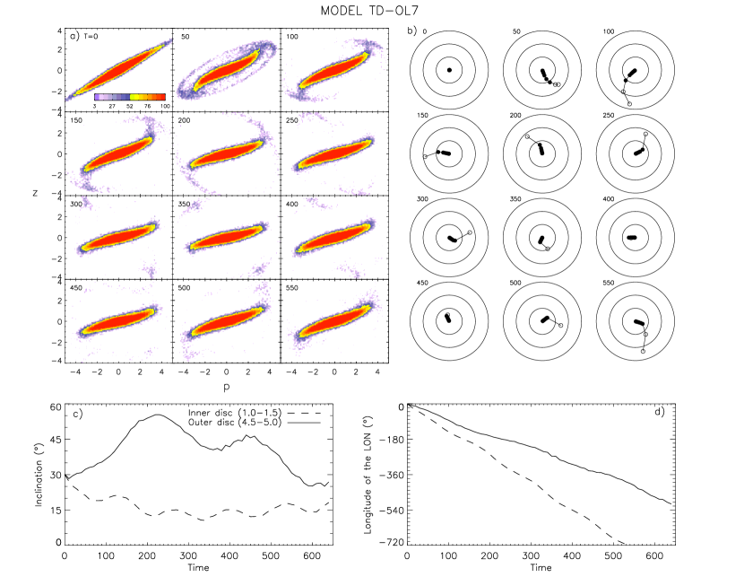
Figure 3 plots the evolution of a disk in our moderately oblate-like halo, model TD-OL7 (note that all of our oblate and oblate-like halos have similar ratios so that they have similar values and thus similar precession rates). It shows that the triaxiality of the halo does not greatly change the global aspect of the evolution. The most significant difference between the oblate and oblate-like cases is that and oscillate periodically in the latter, which is the result of - and -component torques from the triaxial component of the halo, respectively— and are sinusoidal functions when has a non-zero value (see eqs. [A14] and [A15]). The phase of the oscillation coincides with the quadrant of the LON, which indicates that the oscillation is indeed caused by the triaxial component of the halo. As discussed in § 3, when is in the first or third quadrant, the disk experiences a negative -component torque and the inclination increases. Likewise, the inclination decreases when is in the second or fourth quadrant.
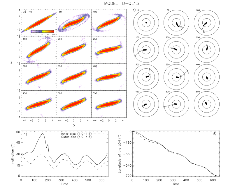
A similar evolutionary picture is observed even in the more extremely oblate-like case, model TD-OL13. Figure 4 shows that the global evolution of this model is very similar to that of model TD-OL7.
In both models TD-OL7 and TD-OL13, the magnitude of the warp slightly oscillates, but the average magnitude of the warp is similar to that of model TD-O. To summarize, when of the halo is negative, the warp in an initially tilted disk scenario is very weak except at the beginning, and even the triaxiality of the halo is not effective in increasing the magnitude of the warp.
4.2 Prolate vs. Prolate-like Halos
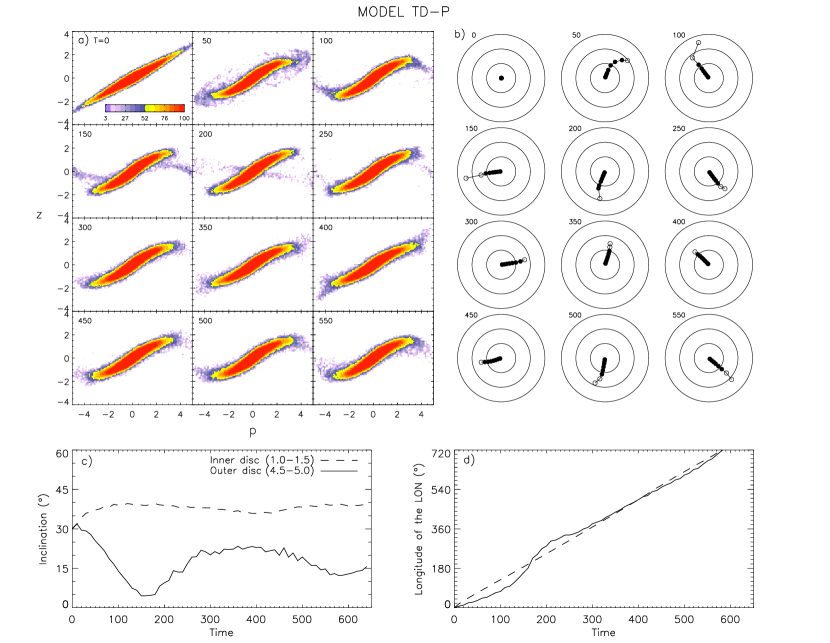
The evolution of the disk in a prolate halo, model TD-P, is shown in Figure 5. Prolate halos exert positive on the disk, and our prolate halos have an absolute precession rate that decreases as increases. Thus the LON undergoes a prograde precession with a shape of a trailing spiral. Because the LON of the outer disk is behind (in the sense of disk spin) that of the inner disk, exerted by the inner disk on to the outer disk is positive, and the inclination of the outer disk decreases (see §3.3) forming a type II warp, which bends down toward the halo equatorial plane. Since a smaller inclination causes a faster precession (; see eq. [A17]), the LON of the outer disk catches up that of the inner disk. If the LON of the outer disk outruns that of the inner disk, the outer disk will have a larger inclination and its precession rate will become smaller. Thus the self-gravity between the inner and outer disks plays a role of restoring force that leads to an alignment of the LONs between the inner and outer disks. The simulation shows that after about one revolution of the precession, the inner and outer disks settle into a stable equilibrium, and the LONs of the two disks remain close to each other afterwards, making the disk observed as a warp.
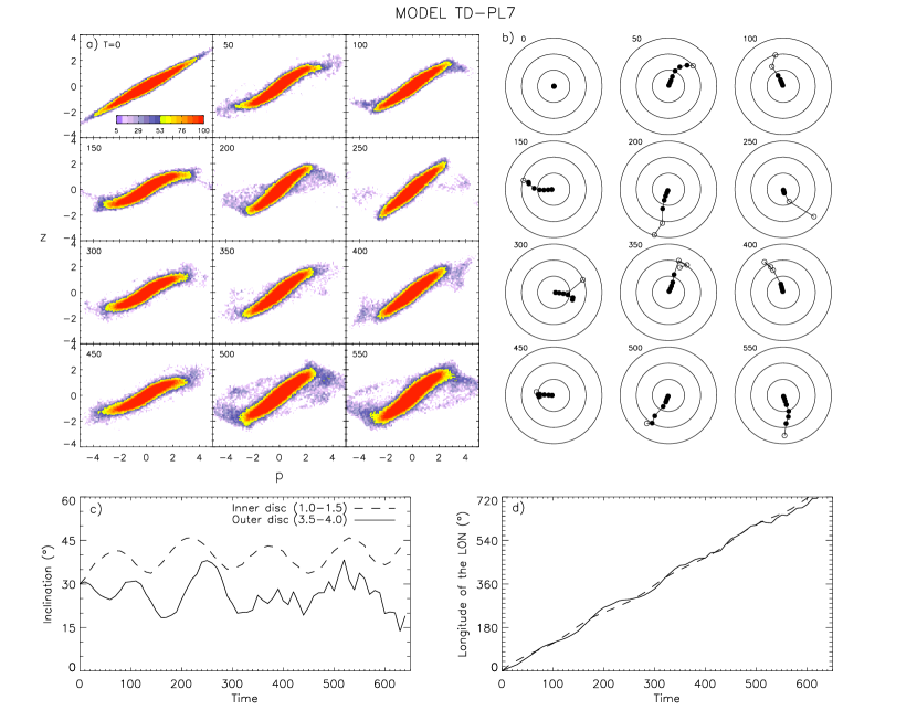
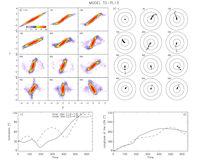
This analysis can be generally applied to the evolution of the disk in a moderately prolate-like halo, model TD-PL7 (Fig. 6). Note that all of our prolate and prolate-like halos have similar ratios so that they have similar precession rates. Again, the most considerable difference from the prolate case is the oscillation in both and . Since the LON of the inner disk advances faster than that of the outer disk in the beginning of the simulation, the oscillation phase of the inner disk is ahead of that of the outer disk afterwards. Because of this phase lag, the inclination gap between the two disks increases and decreases periodically (without the phase lag, the inclinations of the two disks would oscillate with an almost constant gap). Therefore, as seen in panels and , the magnitude of the warp oscillates with a period of precession as well. The warp nearly disappears at and 400, and grows back to its peak at and 500. Note that when the magnitude of the warp reaches its peak, it becomes larger than that of the prolate case with a similar prolateness (). The value of the outermost annulus remains inside in model TD-P, but it reaches near at and 500 in model TD-PL7. Thus the triaxiality of the prolate-like halo periodically suppresses and augments the magnitude of the warp.
In a more extremely prolate-like halo (model TD-PL13), the disk evolves quite differently from the above two cases. As seen in panel of Figure 7, the inclinations of both inner and outer disks increase fairly quickly while oscillating. This appears to be because of the factor in term (eq. [A16])–When the the magnitude of the triaxiality () is large, the peak of the oscillating can reach higher, and at a higher , is larger. Thus when is larger than a certain critical value, the peak value in each oscillation gradually increases and eventually becomes larger than . This happens at for model TD-PL13, after which the LON evolves in the reverse direction because the term in (eq. [A17]) becomes negative.
The large value and thus the large oscillation in of model TD-PL13 causes the outer disk to disperse so severely that it is not recognized as a part of the disk anymore after , making the size of the whole disk appear to be much smaller than in the beginning. The debris from the outer disk spreads out randomly around the inner disk after this epoch, and the warped configuration nearly disappears.
Although panel of Figure 7 shows the evolution up to , we have evolved model TD-PL13 up to and find that after , and of the inner disk keep oscillating around and , respectively, indicating that the disk plane tumbles about the minor axis of the halo. Such a phenomenon has been also observed in numerical and analytical studies on the dynamics of stars and gas in triaxial potentials (Aarseth & Binney 1978; Steiman-Cameron & Durisen 1984; Arnaboldi & Sparke 1994, among others): the particles in triaxial halos prefer the orbits whose principal plane tumbles about its minor axis.
To summarize, when of the halo is positive, an initially tilted disk can excite and sustain the warped configuration for a considerable time as far as the triaxial component of the halo is not too large, and a mild triaxiality can augment the peak magnitude of the warp.
5 TILTED COSMIC INFALL
Now we present and analyze our simulations for the cosmic infall scenario. In these simulations, the disk is initially in the equatorial plane of the halo and the dark matter torus, whose mass gradually increases over , is tilted at relative to the halo equatorial plane such that its ascending LON coincides with the negative -axis.
5.1 Spherical Halo
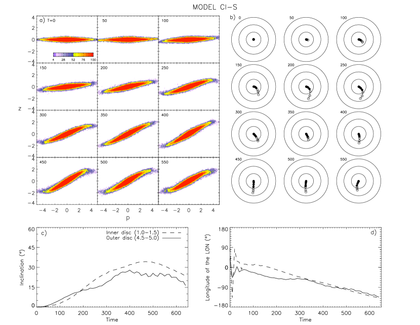
Figure 8 shows the evolution of the disk in a spherical halo (model CI-S). This model is to be compared with the axisymmetric and triaxial halo cases. As the halo in our model CI-S is perfectly spherical, the evolution of the outer disk is driven by the interaction with the torus and with the inner disk only. The tilted torus gives an effect similar to an oblate halo to the disk—it exerts a negative on the disk and makes the disk precess in a retrograde sense about the axis normal to the torus plane. But unlike in model TD-O, the precession rate caused by the torus is an increasing function of (see the Appendix A of Shen & Sellwood 2006 and our Appendix B, but note that the precession rate given in the former is along the torus plane while that in the latter is along the equatorial plane), resulting in a trailing spiral of LON. Thus the inner halo exerts a positive on the outer disk, and the inclination of the outer disk decreases forming a Type II warp.
The inclination relative to the equatorial plane evolves significantly with time (see panel ), but the inclination of the disk relative to the torus plane stays constantly (this phenomenon is to be compared with those in non-spherical halo models below). The increase and decrease of are well explained by equation (B8).
5.2 Oblate and Oblate-Like Halos
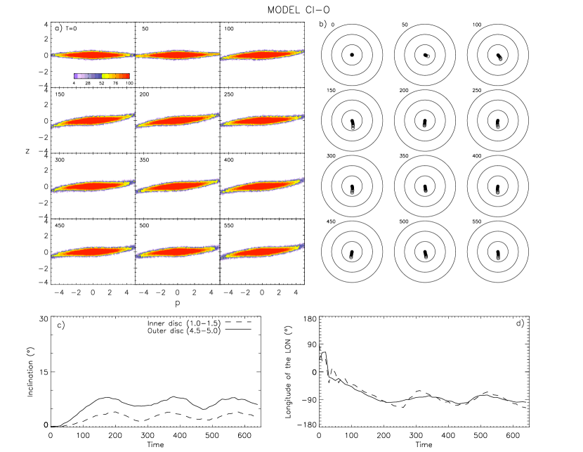
Figure 9 shows the evolution of the disk in an oblate halo (model CI-O). Since the oblate halo does not have a component, the change of is caused only by the accreting torus. Once the value departs from zero, first moves toward and then both and oscillate. The oscillatory behaviors are found to be drived by combined torques from the non-spherical halo and the tilted torus. Figure 10 shows four different sign combinations of and from the combined torques, and the arrangement of the sign combinations is in such a way that the evolution of a point on the – plane follows a round, counterclockwise revolution about the equilibrium point (the point where both and are equal to zero). Note that the center of oscillation, , coincides with the longitude of the ascending node of the torus, but the inclinations of both outer and inner disks are somewhat smaller than that of the torus.
Inclinations of both inner and outer disks oscillate, but since the equilibrium point is located at a higher for a larger , the mean value of the outer disk is higher than that of the inner disk, and thus the disk forms a type-I warp, the opposite of the spherical halo case. Thus in oblate halos, the magnitude of the warp or is determined by the radial gradient of the equilibrium inclination, and is found to be smaller than that in the spherical halo model. Unlike in model TD-O, the values of the inner and outer disks in model CI-O are not significantly separated. This is because in model CI-O, the inclinations of both inner and outer disks are so small that the factors in equations (A17) and (B9) are not so effective in making the two ’s separated as in model TD-O (i.e., the values of the inner and outer disks are similar).
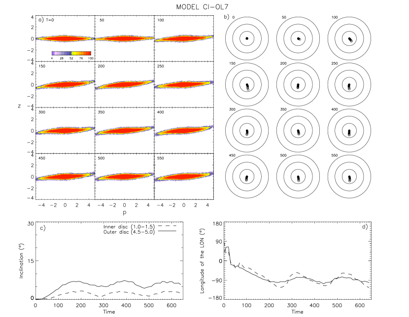
Figure 11 shows the evolution of the disk in one of our oblate-like halos (model CI-OL7). In this model, the shorter of the two halo axes in the equatorial plane aligns with the LON of the torus, thus the oblate-like halo induces a positive when is in the fourth quadrant () and a negative when is in the third quadrant (). Such dependence of is opposite to that by the torus, but the contribution on by the oblate-like halo is much smaller than that by the torus because of the small value of in equation (A16). The average inclinations of both inner and outer disks are smaller than those in the oblate halo model because the equilibrium inclination is smaller for the oblate-like halo model ( in eq. [A17] is negative when is near the equilibrium , ; see Fig. 12). Other than these lowered equilibrium inclinations for both inner and outer disks, the overall evolution of the disk in model CI-OL7 is very similar to that in model CI-O.
We find that the evolution of the disk in model CI-OL7b (figure not presented), where the longer, not the shorter, of the two halo axes in the equatorial plane aligns with the LON of the torus, is very similar to that of model CI-O as well, implying that the orientation of the tilt of the torus relative to the orientation of the oblate-like halo is not an important factor in determining the configuration and the magnitude of the warp. The only noticeable difference between models CI-OL7b and CI-OL7 is the higher average values for both inner and outer disks of the former model because of the positive value in equation (A17) for . Note that, however, all of our oblate and oblate-like halo models have nearly the same magnitudes of the warp (i.e., nearly the same ).
5.3 Prolate and Prolate-Like Halos
Figure 13 shows the evolution of the disk in a prolate halo (model CI-P), which is rather different from those in spherical and oblate halos. In a prolate halo, the magnitude of the warp is much larger, and the outermost part of the disk is even detached from the rest of the disk when the LONs of the outermost part and the main disk are apart by .
This rather large difference is thought to be because of the strong radial dependence of the combined from the halo and the torus. Figure 14 shows that the combined for the prolate halo has a significantly stronger radial dependence than that for the oblate halo. Thus unlike in the oblate halo, the outer disk in the prolate halo can evolve separately from the inner disk from the beginning of the simulation. The LON of the inner disk oscillates around the equilibrium , (see Fig. 15), whereas the LON of the outer disk, which is more affected by the self-gravity within the disk than the inner disk is, appears to experience more complicated evolution. In the beginning of the simulation (), the combined on the outer disk from the halo, torus, and the inner disk is nearly zero, so of the outer disk barely evolves. But once ’s of the inner and outer disks are apart by more than , the second term in equation (C4) becomes negative. This then breaks the subtle equilibirum and makes the outer disk precess in a retrograde fashion.
Unlike in model TD-P, the values of the inner and outer disks in model CI-P are well separated. In model TD-P, the factor in (eq. [A17]) causes the outer disk, which has a smaller than the inner disk, to catch up the of the inner disk. But in model CI-P, the inclinations of the inner and outer disks are both so small in the beginning of the simulation that the factor in the combined from the halo and the torus is not so effective in making the two ’s move together ( is smaller for small ’s).
Because of the inner disk is initially ahead (in the sense of disk spin) of that of the outer disk, the inner disk experiences a positive from the outer disk (see eq. [C3]), thus has an equilibrium value that is higher than the one determined by considering the torques from the halo and torus only as in Figure 15. The value of the outer disk increases in the first half of the simulation and decreases in the second half of the simulation because the combined by the halo and the torus is positive when is in the fourth quadrant and negative when is in the third quadrant (see Fig. 15).
While the evolution of both inner and outer disks in spherical and oblate halos can be explained by the combined torques from the halo and the torus only, in a prolate halo, the self-gravity within the disk plays a non-negligible role in the and evolutions of the disk. This is because in a prolate halo, 1) the term from the inner disk is not negligible as the LONs of the inner and outer disks are well separated from each other (see eq. [C3]), and 2) the term from the inner disk is relatively more important as the values of the halo and the torus have opposite signs.
Figures 16 shows the evolution of the disk in one of our prolate-like halo models (model CI-PL7), where the shorter of the two halo axes in the equatorial plane aligns with the ascending LON of the torus. The evolution of CI-PL7 is generally similar to that of CI-P except that the magnitudes of the warp and the detachment of the outer disk less significant than those in model CI-P. This is because the component of this triaxial halo induces a negative on to the outer disk when is in the fourth quadrant (i.e., during the first half of the simulation), causing the peak that the outer disk acquires to be smaller than that in model CI-P.
Figures 17 shows the evolution of the disk in another prolate-like halo (models CI-PL7b), where the longer of the two halo axes in the equatorial plane aligns with the ascending LON of the torus. The second term in equation (A17) now causes a positive (instead of negative as in model CI-PL7) for the outer disk when , and this apparently balances the negative from the inner disk when the ’s of the inner and outer disks are apart by more than so that of the outer disk stays near after . At this equilibrium , the combined on the outer disk from the halo and the torus is positive (see Fig. 18). Consequently, keeps increasing even after the outer disk is completely detached from the inner disk, and eventually the system resembles polar-ring galaxies.
While the evolutions of the disks in oblate and oblate-like halos are alike and can be described rather simply and coherently without a consideration of the self-gravity within the disk, those in prolate and prolate-like halos sensitively depend on the relative importances between the torques from the halo, the torus, and the disk itself, as well as on the relative orientation between the halo and the torus. The two-disk analysis that we adopted to describe the effect of the self-gravity is found to give qualitatively correct descriptions, but does not give quantitatively accurate estimates for the torques. Thus it is rather difficult to generally describe the evolution of the disk when the self-gravity is not negligible, which is the case of the disks in prolate and prolate-like halos.
6 SUMMARY AND DISCUSSION
We have performed a series of simulations of galactic warps for two scenarios: 1) stellar disks that are initially tilted relative to the equatorial plane of triaxial halos, and 2) stellar disks in axisymmetric or triaxial halos with late infall of dark matter that is modeled as a torus tilted relative to the equatorial plane of the disk and the halo.
In our initially tilted disk (TD) simulations, the triaxiality in the oblate halo does not significantly alter the characteristics and magnitude of the warp, although the latter oscillates as the disk precesses and is smaller for a larger triaxiality. Moderate () triaxiality of the prolate halo results in the warp similar to that in the axisymmetric prolate halo with an oscillatory behavior, while a larger () triaxiality makes the disk precess about the minor axis of the halo, instead of the major axis that the disk initially precessed about, and considerably reduces the magnitude of the warp.
In our cosmic infall (CI) simulations, the magnitude of the warp in the non-spherical halo is determined by the difference in the “equilibrium ” between the inner and outer disks. While the magnitude of the warp in oblate and oblate-like halos is smaller than that in the spherical halo, in prolate and prolate-like halos the warp can grow larger and the outermost part of the disk can even detach from the main disk body. For a prolate-like halo system where the ascending LON of the dark matter torus aligns with the longer of the two halo axes in the equatorial plane, the detachment becomes more extreme and the system resembles polar-ring galaxies. Note that, however, cosmological simulations show that the angular momentum vector of the halo preferentially aligns with the minor axis of the halo (see the references below), thus the disk morphologies found in our prolate and prolate-like halo simulations (detached outer disk and polar-ring configuration) are not expected to take place often.
Regardless of the warp scenario, the triaxiality of the halo causes and to oscillate (i.e., it causes the disk to nutate). the differential nutation between the inner and outer disks generally makes the magnitude of the warp slightly diminish and fluctuate, but this could also cause the outermost part of the disk to completely detach from the main body if this effect is boosted by the torque from the dark matter torus as in model CI-PL7b.
In the Appendices we derived the approximate formulae for the torques exerted on the disk by the triaxial halo and the dark matter torus, and with these formulae, we have successfully described the and evolutions of the disks. The characteristics of the halo and the torus are represented by three parameters , , and , which can be useful in predicting the evolution of a disk in various different halo and torus models, or in estimating the relative importance between the halo and the torus.
The techniques used in deriving these formulae could be applied for halos with more complex structures. Bailin & Steinmetz (2005) found from their CDM -body simulations that the principal axes of the galaxy dark matter halos are internally misaligned (i.e., the directions of the principal axes are functions of galactocentric radius). In such systems, although the stellar disk will quickly be in equilibrium with the inner halo, it may experience torques from the misaligned outer halo for an extended period, and the higher order terms than and might be important. Such configuration could be responsible for U- or L-shaped warps, and for these cases, each radial bin of the disk could be modeled with two broken half-rings, instead of a whole ring.
The main goal of the present study is to understand the fundamental dynamics between the disk and the non-spherical halo (with and without the dark matter torus), thus we have considered models that result in relatively prominent warps (a large initial tilt angle of the disk and a large non-sphericity of the halo). However, most of the observed edge-on disk galaxies have only a hint of warped structure, if any, near –5 in their stellar disks. For example, Ann & Park (2006) found that out of their 325 sample galaxies 165 (51 %) have an S-shaped warp, and 142 (86 %) of these S-shaped warps have warp angles smaller than ( is the inclination angle of the tip of the outermost isophotes from the mean disk major axis, and is very close to our ).
Our simulations for the initially tilted disk scenario show that prolate and prolate-like halo models can excite more prominent warps than oblate and oblate-like halo models. However, this does not necessarily imply that, as Ideta et al. (2000) interpreted, oblate and oblate-like models are not appropriate to explain the observed warps–they may not be able to sustain a prominent warp, but surely can resemble the majority of the observed warps, i.e., those with small values. On the other hand, prolate and prolate-like models can explain warps with both large and small values by having different initial tilt angles or halo axis ratios. Figure 19 shows that can become smaller if prolate and prolate-like models have an initial tilt angle of , instead of , or a halo axis ratio of , instead of 0.75.
Our simulations for the tilted cosmic infall scenario also show that prolate and prolate-like halo models can excite more prominent warps than oblate and oblate-like halo models. The outermost disk in those models can detach from the main disk body or even form a polar ring at least for some time, but such systems are barely observed. The magnitude of the warp is suppressed in oblate and oblate-like halos, and is even smaller than in the spherical halo. Thus for the cosmic infall scenario, the way to obtain a nice and clean, prominent warp would be to have a (nearly) spherical halo and/or dark matter infall that gives a large value.
These results appear to be consistent with the recent cold dark matter cosmological simulations. Bailin et al. (2005) found in their hydrodynamic simulations that the (inner) halo minor axes are nearly aligned with the disk axis, and Bett et al. (2007) analyzed the Millennium simulation (Springel et al. 2005) to find that the majority of halos have their angular momentum vector aligned with their minor axis. Both of these, which confirm the findings of earlier studies by Dubinski (1992) and Warren et al. (1992), imply that most of the disks are situated in an oblate or oblate-like halo, and can explain why 1) most of the observed warps are quite weak (warps are suppressed in oblate and oblate-like halos) and 2) disks with detached outer part or polar-ring systems are not observed or rare.
Appendix A Approximate Torques by the Triaxial Halo
Here we derive approximate torques exerted on a ring of disk material by triaxial halos following the procedure in Steiman-Cameron & Durisen (1984), who considered the halo mass distribution inside the ring only. We extend their work and consider the halo mass distribution both inside and outside the radius of the ring. We then derive the rates of changes in inclination and LON of the ring due to the non-spherical components of the halo.
Gravitational potential from a mass distribution can be written as an expansion in spherical harmonics ,
| (A1) |
Here are the -coefficients of the shell lying between and ,
| (A2) |
where are the spherical Legendre conjugate functions, and is the solid angle element. Then the first-order corrections to the potential can be written as
| (A3) |
where and are defined by
| (A4) |
and
| (A5a) | |||||
| (A5b) | |||||
| (A6a) | |||||
| (A6b) | |||||
Oblate halos have negative values while prolate halos have positive ’s. Also note that oblate and prolate halos have , and triaxial halos with () have positive (negative) ’s.
Now with equations (A16) to (A18) of Steiman-Cameron & Durisen (1984), the average first-order potential corrections for a ring of disk material that has a radius of , inclination , and the longitude of ascending LON become
| (A7) |
If the spin of the ring is much faster than the precession or the inclination change of the ring, the Lagrange equations of motion for the ring become
| (A8) | |||||
| (A9) |
(Habe & Ikeuchi 1985), where , the circular (spin) velocity of the ring, is defined to be positive when the ring spins counterclockwise when viewed from the positive -axis, and the Hamiltonian equations of motion for the ring yield
| (A10) | |||||
| (A11) |
(Arnaboldi & Sparke 1994). Since the -axis coincides with the LON, we have
| (A12) |
and since the -component angular momentum of the ring is , we have
| (A13) |
(see §3 for the definitions of - and - axes). Now the and components of the torque become
| (A14) | |||||
| (A15) | |||||
Finally, from equations (A8), (A9), (A14), and (A15), the rate of inclination change and the precession rate can be given by
| (A16) | |||||
| (A17) | |||||
Appendix B Approximate Torques by the Dark Matter Torus
Here we derive approximate torques exerted on a ring of disk material by the accreting torus of a mass that is inclined at from the equatorial (-) plane of the halo with the ascending LON aligned with the negative -axis. We assume that the torus has an infinitesimally small cross section and a radius of that is larger than that of the ring.
The potential by the torus does not have terms as in the case of triaxial halos, but it does have terms besides terms. Then the first-order corrections to the potential can be written as
| (B1) |
We find that the coefficients , , and have the following forms for the torus:
| (B2) | |||||
| (B3) | |||||
| (B4) |
Now with equations (A16) to (A18) of Steiman-Cameron & Durisen (1984), the average first-order potential corrections for a ring of disk material that has a radius of , inclination , and the longitude of ascending LON become
| (B5) |
Then from equations (A14) and (A15), the and component torques are given by
| (B6) | |||||
| (B7) |
and as in Appendix A, the rate of inclination change and the precession rate are given by
| (B8) | |||||
| (B9) | |||||
Note that for our torus, terms are negligible compared to the other terms (see Table 2).
Shen & Sellwood (2006) derives the precession rate of a disk due to an accreting torus by assuming that the torus lies in the equatorial plane and the disk is inclined at a certain angle relative to the equatorial plane (note that our and are defined to be the inclination and the LON respectively in the coordinates where the torus is inclined relative to the equatorial plane; when the torus lies in the equatorial plane, the inclination of the disk does not change and only of the disk evolves). The rates of changes in and can be also derived from the precession rate by Shen & Sellwood,
| (B10) |
where is the LON of the disk along the torus plane and is the inclination of the disk relative to the torus plane. By transforming the coordinates from the torus plane to the equatorial plane, one obtains the following rates of changes:
| (B11) | |||||
| (B12) |
The term in can be transformed to the equatorial coordinates by
| (B13) |
Appendix C Approximate Torques by the Inner Disk
Here we estimate approximate torques on the outer disk by the inner disk using the results obtained in Appendix B. If the inner disk is considered in place of the torus, equations (B2) and (B3) can be written as
| (C1) | |||||
| (C2) |
and the rates of changes become
| (C3) | |||||
| (C4) |
where the variables with a subscript are for the inner disk and those with no subscripts are for the outer disk.
References
- (1) Aarseth, S. J. & Binney, J. 1978, MNRAS, 185, 227
- (2) Allgood, B., Flores, R. A., Primack, J. R., Kravtsov, A. V., Wechsler, R. H., Faltenbacher, A., & Bullock, J. S. 2006, MNRAS, 367, 1781
- (3) Ann, H. B. & Park, J.-C. 2006, NewA, 11, 293
- (4) Arnaboldi, M., & Sparke, L. S. 1994, ApJ, 107, 958
- (5) Bailin, J., & Steinmetz, M. 2005, ApJ, 627, 647
- (6) Bailin, J., et al. 2005, ApJ, 627, L17
- (7) Bett,P., Eke, V., Frenk, C. S., Jenkins, A., Helly, J., & Navarro, J. 2007, MNRAS, 376, 215
- (8) Binney, J., Jiang, I.-G., & Dutta, S. 1998, MNRAS, 297, 1237
- (9) Binney, J., & Tremaine, S. 2008, Galactic Dynamics, 2nd ed., Sec. 2.5.3 (Princeton: Princeton University Press)
- (10) Briggs, F. H. 1990, ApJ, 352, 15
- (11) Chandrasekhar, S. 1969, Ellipsoidal Figures of Equilibrium (New York: Dover)
- (12) Dehnen, W. 1993, MNRAS, 265, 250
- (13) Dekel, A., & Shlosman, I. 1983, in IAU Symp. 100, Internal Kinematics and Dynamics of Galaxies, ed. E. Athanassoula, (Dordrecht: Reidel Publishing Co.), 187
- (14) Dubinski, J. 1992, ApJ, 401, 441
- (15) Dubinski, J., & Kuijken, K. 1995, ApJ, 442, 492
- (16) Elwert, G., & Hablick, D. 1965, ZA, 61, 273
- (17) Habe, A., & Ikeuchi, S. 1985, ApJ, 289, 540
- (18) Hurnquist L. 1993, ApJS, 86, 389
- (19) Hunter, C., & Toomre, A. 1969, ApJ, 155, 747
- (20) Ideta, M., Hozumi, S., Tsuchiya, T., & Takizawa, M. 2000, MNRAS, 311, 733
- (21) Jiang, I.-G., & Binney, J. 1999, MNRAS, 303, L7
- (22) Jing, Y. P., & Suto, Y. 2002, ApJ, 574, 538
- (23) Kahn, F. D., & Woltjer, L. 1959, ApJ, 130, 705
- (24) Kellogg, O. D. 1953, Foundations of Potential Theory (New York: Dover)
- (25) Lopez-Corredoira, M., Betancort-Rijo, J., & Beckman, J. E. 2002, A&A, 386, 169
- (26) Lynden-Bell, D. 1965, MNRAS, 129, 299
- (27) Merritt, D., & Fridman, T. 1996, ApJ, 460, 136
- (28) Nelson, R. W., & Tremaine, S. 1995, MNRAS, 275, 897
- (29) Oh, S. H., Kim, W.-T., Lee, H. M., & Kim, J. 2008, ApJ, 683, 94
- (30) Ostriker, E. C., & Binney, J. J. 1989, MNRAS, 237, 785
- (31) Revaz, Y., & Pfenniger, D. 2001, in Gas and Galaxy Evolution, ed. J. E. Hibbard, M. Rupen, & J. H. van Gorkom, San Francisco, ASP Conf. Proc., 240, 278
- (32) Shen, Juntai & Sellwood, J. A. 2006, MNRAS, 370, 2
- (33) Sparke, L. S., & Casertano, S. 1988, MNRAS, 234, 873
- (34) Springel, V., Yoshida, N.,& White, S. D. M. 2001, NewA, 6, 79
- (35) Springel, V., et al. 2005, Nature, 435, 629
- (36) Steiman-Cameron, T. Y. & Durisen, R. H. 1984, ApJ, 276, 101
- (37) Toomre, A. 1983, in IAU Symp. 100, Internal Kinematics and Dynamics of Galaxies, ed. E. Athanassoula, (Dordrecht: Reidel Publishing Co.), 177
- (38) Warren, M. S., Quinn, P. J., Salmon, J. K., & Zurek, W. H. 1992, ApJ, 399, 405
| Halo | ||||||||
|---|---|---|---|---|---|---|---|---|
| Model | Remark | Torus | ||||||
| Initially Tilted Disks | ||||||||
| TD-O | 10 | 10 | 7.5 | Oblate | No | |||
| TD-OL7 | 10.7 | 9.3 | 7.5 | Oblate-like, 7 % | No | |||
| TD-OL13 | 11.3 | 8.7 | 7.5 | Oblate-like, 13 % | No | |||
| TD-P | 7.5 | 7.5 | 10 | Prolate | No | |||
| TD-PL7 | 8.03 | 6.98 | 10 | Prolate-like, 7 % | No | |||
| TD-PL13 | 8.48 | 6.53 | 10 | Prolate-like, 13 % | No | |||
| Tilted Cosmic Infall | ||||||||
| CI-S | 10 | 10 | 10 | Spherical | Yes | |||
| CI-O | 10 | 10 | 7.5 | Oblate | Yes | |||
| CI-OL7 | 10.7 | 9.3 | 7.5 | Oblate-like, 7 % | Yes | |||
| CI-OL7b | 9.3 | 10.7 | 7.5 | Oblate-like, 7 % | Yes | |||
| CI-P | 7.5 | 7.5 | 10 | Prolate | Yes | |||
| CI-PL7 | 8.03 | 6.98 | 10 | Prolate-like, 7 % | Yes | |||
| CI-PL7b | 6.98 | 8.03 | 10 | Prolate-like, 7 % | Yes | |||
| Model | |||||||||
|---|---|---|---|---|---|---|---|---|---|
| Halo | |||||||||
| TD/CI-O | 5.05E-2 | 6.67E-2 | |||||||
| TD/CI-OL7 | 5.00E-2 | 1.22E-2 | 6.62E-2 | 1.62E-2 | |||||
| TD/CI-OL13 | 4.90E-2 | 2.28E-2 | 6.49E-2 | 3.09E-2 | |||||
| TD/CI-P | 5.84E-2 | 7.61E-2 | |||||||
| TD/CI-PL7 | 5.89E-2 | 1.43E-2 | 7.66E-2 | 1.81E-2 | |||||
| TD/CI-PL13 | 6.01E-2 | 2.66E-2 | 7.78E-2 | 3.36E-2 | |||||
| Torus | |||||||||
| All | 7.31E-3 | 1.02E-3 | 2.72E-4 | 2.93E-2 | 4.07E-3 | 1.09E-3 | |||