Electromagnetically Induced Transparency and Light Storage
in an Atomic Mott Insulator
Abstract
We experimentally demonstrate electromagnetically induced transparency and light storage with ultracold 87Rb atoms in a Mott insulating state in a three dimensional optical lattice. We have observed light storage times of ms, to our knowledge the longest ever achieved in ultracold atomic samples. Using the differential light shift caused by a spatially inhomogeneous far detuned light field we imprint a “phase gradient” across the atomic sample, resulting in controlled angular redirection of the retrieved light pulse.
pacs:
37.10.Jk, 42.50.GyCoherent interaction between light and matter plays an important role in many quantum information and quantum communication schemes Duan01 ; Lukin03 . In particular, it is desirable to transfer quantum states from photonic, “flying” qubits to matter-based systems for storage and processing Masalas04 . In this context, electromagnetically induced transparency (EIT) has proven extremely useful, since it allows an incoming light pulse to be converted into a stationary superposition of internal states and back into a light pulse Fleischhauer03 ; Lukin00 ; Liu01 ; Philips01 . This effect has successfully been used to map quantum states of light onto cold atomic ensembles Kimble08 or even to transmit quantum information between two such remote quantum memories Chaneliere05 . EIT and light storage have been realized in crystals Turukhin02 , atomic vapors Kash99 ; Philips01 and in ultracold atomic ensembles Hau99 ; Liu01 ; Ahufinger2002 . In crystals, storage times of several seconds have been achieved Longdell05 . In vapor cells, inelastic collisions with other atoms or with the walls usually limit the coherence times to a few milliseconds Julsgaard04 ; Klein06 . In cold atomic samples the light storage times are also on a millisecond timescale Liu01 . Using magnetically insensitive states, storage times of up to 6 ms were recently observed even for single quantum excitations in cold atomic gases, limited by loss of atoms BZhao2009 or thermal diffusion RZhao2009 .
Ultracold atoms in a Mott insulator (MI) state with unity filling in a deep 3D optical lattice are ideal for light storage, as they experience no diffusion and no collisional interaction. In the present work, we demonstrate EIT and long light storage in such an environment. The minimal dephasing observed allows for many possibilities for processing stored information using advanced manipulation techniques for atomic many-body states in optical lattices (see Ref. BlochRMP and references therein). Light pulses can be stored in an atomic spin wave in the MI, transformed, and then efficiently mapped back into photonic modes. As an example of such a spin-wave manipulation, we imprint a “phase gradient” across the atomic sample using a spatially varying differential light shift of the two ground state levels. This spatial phase gradient results in a controlled change of the direction of the restored pulse. By controlling non-classical atomic spin excitations, atoms in optical lattices could even be turned into novel non-classical light sources Porras:2008 ; Pedersen:2008 or lead to deterministic photonic phase gates at the single photon level Masalas04 .
In our experiment we begin with ultracold 87Rb atoms in the state in an optical lattice consisting of three mutually orthogonal retroreflected laser beams each with -radius m. Two of the lattice beams are red detuned ( nm), while the third is blue detuned ( nm). In a sufficiently deep lattice (; is the recoil energy), the many-body ground state is a MI with a well-defined number of atoms on each lattice site.
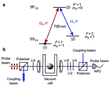
For EIT, we use a -system consisting of the two Zeeman sublevels and of the 5S1/2 ground state, and the level of the 5P1/2 excited state [Fig. 1(a)]. At a field of G, the states and have the same first-order Zeeman shift Harber02 . The coupling laser light with Rabi frequency is -polarized and is resonant with the transition. The probe laser (Rabi frequency , frequency , -pol.) is phase locked to the coupling laser with a difference frequency corresponding to the ground state hyperfine splitting. We use a collinear arrangement of probe- and coupling beams [Fig. 1(b)] in order to avoid momentum transfer to the atoms. The two beams are overlapped on a Glan-Thompson polarizer before a waveplate converts the linear into circular polarizations. A lens system focusses the beams onto the atomic sample. The coupling beam has a 1/e2-radius of m, much larger than the diameter of the atomic sample (typically m), in order to facilitate the alignment and to create a spatially homogeneous coupling laser field. The probe laser beam has a radius of m. The outgoing beams are separated using polarization optics (suppression ratios of ) and the probe beam is directed onto an avalanche photodiode (APD, Analog Modules 712A-4).
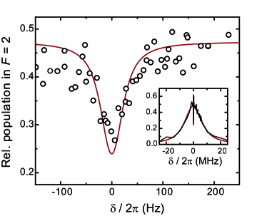
We first observe EIT, in particular the existence of a narrow transmission window, in an atomic sample of atoms, which in our system corresponds to a MI with only singly occupied sites. The atomic sample is an ellipsoid with radii m and m. We shine in the coupling laser ( kHz) and a weak probe laser pulse ( kHz) for 200 ms. Due to the small system size and low powers necessary to achieve such a narrow EIT window, a direct measurement of probe transmission through the atom cloud is difficult in our case. Instead, we measure the fraction of atoms transferred by the probe laser to the manifold. We first detect the number of atoms in by resonant absorption imaging. A second image is taken s later with a repumper in order to also detect the atoms in the manifold (). The graphs in Fig. 2 show the relative population transfer as a function of the two-photon detuning. We observe an EIT transmission window ( Hz FWHM) at the center of the absorption line. We calculate the fraction of atoms pumped from into the manifold by a rate equation model. It includes the analytic expression for the linear susceptibility given in Ref. Fleischhauer03 and also accounts for the inhomogeneous optical depth (OD), which arises from the ellipsoidal cloud shape. To explain the observed population transfer to also at the center of the EIT window, we include a decay rate of the coherence Hz and transfer to by a fraction of -polarized probe laser light () on the transition. The best agreement with the data is obtained with kHz, kHz and (red line in Fig. 2), which are close to the measured values.
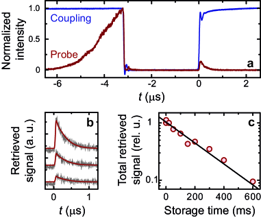
As a second experiment, we demonstrate the storage of light pulses (Fig. 3). After turning on the coupling beam, we apply a Gaussian-shaped probe pulse with 2.8 s FWHM. At the peak of this pulse, we shut off the probe and coupling beams simultaneously, within less than 50 ns. After waiting for a variable storage time, we turn on the coupling beam again and monitor the restored probe pulse on an APD. The second, retrieved pulse is much smaller than the first, incident pulse. From the ratio of their areas, we estimate the storage efficiency to be 3% for a large thermal cloud [Fig. 3(a)] and 0.3% for the MI. The small efficiency is partly caused by the mismatch of the size of the probe beam and the atomic sample (18% geometrical overlap for the MI), leakage of the probe beam due to the finite OD of the sample (peak OD , see definition in Ref. Lukin03 ), and due to spontaneous emission during writing and retrieval phases. From numerical simulations based on the equations in Phillips08 , we estimate the efficiencies due to leakage and spontaneous emission as 11% for short storage times (s). The same simulations were used to reproduce the retrieved pulse shapes shown in Fig. 3(b) with no free parameters other than the amplitude. Not included in the simulations are effects due to imperfect polarizations of probe and coupling beams.
We use the energy (integrated intensity) of the restored pulse as a measure of the stored light signal. As shown in Fig. 3(c), fitting an exponential decay to the retrieved pulse power as a function of storage time yields a decay time constant of ms. To independently measure the coherence time of the superposition, we performed a Ramsey experiment on the same states using an rf+microwave two-photon transition Harber02 . The visibility of the Ramsey fringes decays with a time constant of ms, indicating that the decay of the stored light pulse is not caused by residual coupling light present during the storage time. The factor of two arises since the Ramsey fringe contrast measures the decay of the quantum amplitude coherence Widera2002 , whereas in the EIT signal we measure an intensity. A -echo pulse does not restore the Ramsey signal contrast, so the decay time has to be attributed to an irreversible dephasing mechanism. We have ruled out magnetic field noise by measuring coherence times away from the “magic” field at 3.23 G. The coherence times are nearly unchanged at 6 G and 2 G, where the differential shift of the transition is at least an order of magnitude more sensitive to magnetic field fluctuations. We measured the coherence time vs lattice depth and found a maximum at for our experimental parameters. This indicates that the source of the coherence decay is due to heating in the optical lattice and to finite tunneling. The latter leads to an increased probability of having more than one atom per lattice site. In this case the interaction energy in the doubly occupied sites leads to an onsite dephasing with respect to the singly occupied sites. Increasing the lattice depth improves the coherence times due to the suppression of tunneling, but in turn the heating due to spontaneous light scattering and technical noise increases. Our analysis suggests that by simply using farther detuned lattices, even longer light storage times can be achieved.
In a non-collinear geometry, the difference in the wavevectors of coupling and probe beams, , is stored as a spatial gradient in the phase of the atomic superposition state Liu01 :
| (1) |
Here we reverse the logic leading to Eq. (1), and show that imprinting a phase gradient on a stored-light state can change the direction of the restored pulse. This is similar to the work demonstrating deflection of light in a vapor cell by a magnetic gradient field Weitz06 or by an inhomogeneous laser beam Sautenkov07 . In our experiment, we first store a pulse in a MI with atoms, and a lattice depth of using the sequence described above ( MHz, MHz).
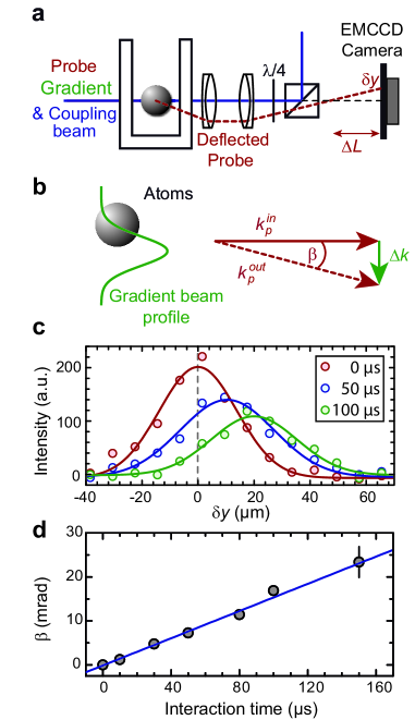
Before retrieving the pulse after 10 ms storage time, we shine in an additional polarized laser (m), aligned m away from the center of the atomic cloud [Fig. 4(b)]. The laser is red detuned from the transition by GHz, which causes spatially inhomogeneous light shifts of the two ground state levels due to the Gaussian intensity profile. Shining in this laser for an interaction time induces a local dephasing between and of . In our experiment, the maximum laser intensity is W/cm2, which produces a differential light shift of kHz at the center of the atomic cloud. The interaction time is varied from to s. The deflection angle is
| (2) |
where is the wavevector of the probe laser beam.
The deflected pulse is detected using an electron multiplying CCD (EMCCD, ANDOR iXon DV885), see Fig. 4(a). In order to reveal the deflection, the camera is placed out of the focal plane by translating the last lens before the camera. The detected signal on the EMCCD camera for s contains about counts (corresponding to photons). This signal was then summed along the -direction and averaged over runs for better visibility. To each of these integrated pulses we fit a 1D Gaussian and determine the position shift of the deflected beam. From and the camera position with respect to the focal plane, we determine the deflection angle . The result is summarized in Fig. 4(d) together with a linear fit. The fitted slope rad/s is close to the value of rad/s calculated from our experimental parameters. The error takes into account the uncertainties of the gradient beam power, waist and the alignment.
In summary we have demonstrated EIT, light storage and retrieval from an atomic Mott insulator. We have observed very long storage times of about 240 ms, where the storage time is limited by heating from the lattice and by tunneling. We also demonstrated that a stored pulse can be controlled and redirected by imprinting a spatial phase gradient with a laser beam.
In the future, it would be interesting to extend this technique to more complex light fields in order to process and manipulate information stored in spin structures, which can then be analyzed by measuring the direction and shape of the retrieved pulse. In contrast two the usual manipulation of the spins by microwave radiation, EIT also allows the imprinting of elaborate phase structures generated by holograms such as images or vortices Davidson07 . This could facilitate the study of far-from equilibrium spinor gases, or allow the storage of a doubly charged vortex in the MI phase, where it is expected to be stable in contrast to a BEC Shin2004 . Another interesting prospect is to use the MI as a genuine quantum memory to store and to retrieve single photons BZhao2009 ; RZhao2009 . By using an optimized geometry with a higher OD, storage of an entire pulse or pulse sequence can be achieved. As an alternative to storing light pulses, one can also directly create an atomic superposition. Turning on the coupling field then leads to the creation of a probe field. We are currently exploring the use of such a created light pulse as a novel probe for classical or entangled atomic spin states in an optical lattice. Ultimately, the generation of such non-classical spin states and the direct mapping onto photonic states could lead to a new generation of non-classical light sources Porras:2008 ; Pedersen:2008 .
We acknowledge support by DIP, DFG, EU (IP SCALA), AFOSR, and DARPA (OLE) and the Fulbright Association (J.D.T.). We thank A. V. Gorshkov for helpful discussions.
References
- (1) L.-M. Duan, M. D. Lukin, J. I. Cirac, and P. Zoller, Nature 414, 413 (2001).
- (2) M. D. Lukin, Rev. Mod. Phys. 75, 457 (2003).
- (3) M. Mašalas and M. Fleischhauer Phys. Rev. A 69, 061801(R) (2004).
- (4) M. Fleischhauer, A. Imamoglu, and J. P. Marangos, Rev. Mod. Phys. 77, 633 (2005).
- (5) M. D. Lukin, S. F. Yelin, and M. Fleischhauer, Phys. Rev. Lett. 84, 4232 (2000); M. Fleischhauer and M. D. Lukin, Phys. Rev. Lett. 84, 5094 (2000).
- (6) C. Liu, Z. Dutton, C. H. Behroozi, L. V. Hau, Nature 409, 490 (2001).
- (7) D. F. Phillips et al., Phys. Rev. Lett. 86, 783 (2001).
- (8) H. J. Kimble, Nature 453, 1023 (2008).
- (9) T. Chanelière et al., Nature 438, 833 (2005).
- (10) A. V. Turukhin et al., Phys. Rev. Lett. 88, 023602 (2002).
- (11) M. M. Kash et al., Phys. Rev. Lett. 82, 5229 (1999).
- (12) L. V. Hau, S. E. Harris, Z. Dutton, and C. H. Behroozi, Nature 397, 594 (1999).
- (13) V. Ahufinger et al., Opt. Commun. 211, 159 (2002).
- (14) J. J. Longdell, E. Fraval, M. J. Sellars, and N. B. Manson, Phys. Rev. Lett. 95, 063601 (2005).
- (15) M. Klein, I. Novikova, D. F. Phillips, and R. L. Walsworth, J. Mod. Opt. 53, 2583 (2006).
- (16) B. Julsgaard et al., Nature 432, 482 (2004).
- (17) B. Zhao et al., Nature Phys. 5, 95 (2009).
- (18) R. Zhao et al., Nature Phys. 5, 100 (2009).
- (19) I. Bloch, J. Dalibard, and W. Zwerger, Rev. Mod. Phys. 80, 885 (2008).
- (20) D. Porras and J. I. Cirac, Phys. Rev. A 78, 053816 (2008).
- (21) L. H. Pedersen and K. Mølmer, Phys. Rev. A 79, 012320 (2009).
- (22) D. M. Harber, H. J. Lewandowski, J. M. McGuirk, and E. A. Cornell, Phys. Rev. A 66, 053616 (2002).
- (23) N. B. Phillips, A. V. Gorshkov, and I. Novikova, Phys. Rev. A 78, 023801 (2008).
- (24) A. Widera et al., Phys. Rev. Lett. 92, 160406 (2004).
- (25) L. Karpa and M. Weitz, Nature Phys. 2, 332 (2006).
- (26) V. A. Sautenkov, H. Li, Y. V. Rostovtsev, M. O. Scully, arXiv:quant-ph/0701229v1 (2007).
- (27) R. Pugatch et al., Phys. Rev. Lett. 98, 203601 (2007).
- (28) Y. Shin et al., Phys. Rev. Lett. 93, 160406 (2004); J. A. M. Huhtamäki et al., Phys. Rev. Lett. 97, 110406 (2006).