Excitonic spin density wave state in iron pnictides
Abstract
We examine the appearance of a spin density wave in the FeAs parent compounds due to an excitonic instability. Using a realistic four-band model, we show that the magnetic state depends very sensitively upon the details of the band structure. We demonstrate that an orthorhombic distortion of the crystal enhances the stability of the antiferromagnetic order.
pacs:
75.30.Fv,75.10.LpIntroduction. The superconductivity of materials containing FeAs layers is currently receiving much attention. Like the cuprates, these systems become superconducting upon chemical doping of an antiferromagnetic (AF) parent compound, specifically ReFeAsO (Re is a rare earth ion) or AeFe2As2 (Ae is an alkaline earth ion). Kamihara2008 ; Rotter2008 Intriguingly, the AF state occurs only in the presence of an orthorhombic distortion of the crystal, which fixes the AF ordering direction. 1111coupling ; 122coupling The likely role of spin fluctuations in producing the superconductivity has lead to intense scrutiny of the AF phase. The relatively small value of the moment at Fe sites, 1111coupling ; 122coupling ; McGuire2008 metallic transport properties, McGuire2008 ; Hu2008 and observations of reconstructed Fermi surfaces, magneto ; ARPES provide strong evidence that the AF state is a spin density wave (SDW) arising from the nesting of electron and hole Fermi surfaces. Mazin2008 ; Singh2008 ; Korshunov2008
In analogy to Cr, Rice1970 a theory of the SDW based upon the excitonic pairing of electrons and holes has been proposed. Han2008 ; Chubukov2008 ; Vorontsov2008 It is important to determine if this scenario is sufficient to explain the AF state, or whether a more complicated multi-orbital approach is required. Kuroki2008 ; Ran2009 ; Yu2008 ; Korshunov2008 ; Lorenzana2008 As previous works have used a highly-idealized model of the electronic structure, Han2008 ; Chubukov2008 ; Vorontsov2008 with only two Fermi surfaces instead of the likely four or more, Mazin2008 ; Singh2008 it is not clear if the excitonic SDW can give the observed magnetic ordering. 1111coupling ; 122coupling Furthermore, the effect of the orthorhombic distortion on such a state remains unknown. We address these problems here by studying the appearance of the excitonic SDW in a four band model of LaFeAsO. Korshunov2008 Using a mean-field theory, we show that the SDW state is sensitively dependent upon the doping and the details of the band structure. Mazin2009 In particular, we examine the response of the SDW phase to changes in the ellipticity of the electron pockets, the relative size of the hole pockets, and an orthorhombic distortion of the crystal.
Theoretical model. We model the FeAs planes as a 2D interacting four-band system where two bands have electron-like Fermi surfaces and the other two have hole-like Fermi surfaces. We write the Hamiltonian as
| (1) | |||||
where () creates a spin- electron with momentum in the electron-like (hole-like) band . Due to the out-of-plane arrangement of the As ions, the crystallographic unit cell of the FeAs plane contains two Fe ions. Our band structure is given in terms of this unit cell, but in the discussion of magnetic properties it is more useful to refer only to the Fe lattice, which requires us to “unfold” the Brillouin zone. Mazin2008 Assuming crystallographic unit-cell dimensions , the bands with electron-like Fermi surface have dispersion , while for the hole-like bands we have . In units of eV, we use , , , , , , , , and . We keep only the bands which intersect the Fermi surface. For electron filling , corresponding to the undoped parent compounds, we find the dispersion and Fermi surface as shown in Fig.s 1(a) and (b), respectively. Note that the nesting of the hole and electron Fermi surfaces is not perfect, since both the shape and the enclosed area differ. Our model reproduces the Fermi surface and low-energy velocities of the band structure proposed in LABEL:Korshunov2008 for LaFeAsO, but unlike LABEL:Korshunov2008 obeys the correct periodicity of the Brillouin zone.
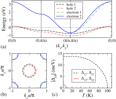
The interaction terms in Eq. (1) describe a density-density interaction and correlated transitions between the electron and hole bands, with contact potentials and , respectively. At low temperatures, the system is unstable against the pairing of electrons and holes, producing an excitonic state. Rice1970 ; Excitonic ; Kopaev1970 Although a rich variety of excitonic phases are possible, here the SDW state has the largest effective coupling constant . Chubukov2008 ; Buker1981 At mean-field level, we therefore decouple the interaction terms via the introduction of the real SDW excitonic averages where is the nesting vector [see Fig. 1(b)] and takes values of or to index the electron (hole) bands. is regarded as the order parameter of the SDW state, Rice1970 ; Excitonic although it is only indirectly related to the staggered magnetization. Buker1981 As each electron pocket is mapped to a different X point of the enlarged Brillouin zone upon unfolding, Mazin2008 the and involve orthogonal nesting vectors and with respect to the Fe sites, respectively. When both and are non-zero, therefore, the magnetization is the superposition of two orthogonal SDW states, each with stripe-like ordering. Lorenzana2008
After decoupling the interaction terms, we obtain the equilibrium mean-field solution by numerical minimization of the free energy with respect to the . This was calculated over the 2D Brillouin zone with at least a -point mesh. Throughout this work we set the effective SDW coupling constant to be eV, as at this gives a partially-gapped Fermi surface in the SDW state with reasonable critical temperatures: as shown in Fig. 1(c) we find that is non-zero below K, while appears below K. When all four averages are non-zero, we find the inequality ; when only two are present, their signs are independent.
Ellipticity of the electron pockets. As seen in Fig. 1(c), both electron bands participate in the excitonic instability at . This corresponds to a SDW, whereas only a single- SDW is experimentally observed. 1111coupling ; 122coupling It has previously been noted that these two SDW phases should lie at similar energies, Yu2008 and so it is interesting to see whether slight changes in the band structure can stabilize a single- state. This might be achieved, for example, by reducing the ellipticity of the two electron pockets so as to enhance their competition for the same states in each hole band. We therefore modify the electron dispersions , where the dimensionless parameter controls the ellipticity of the electron pockets. We compare the electron pockets at and in Fig. 2(a).
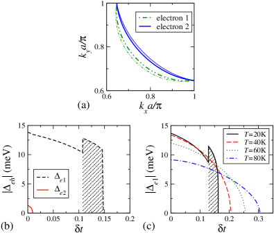
We find that even very small values of can qualitatively alter the mean-field state. The evolution of the with increasing at K is plotted in Fig. 2(b). Reducing the ellipticity of the electron pockets tends to suppress the excitonic state, with disappearing before is reached. At the system undergoes a first-order transition from the state into a single- state. A single- state is hence possible at mean-field level by subtle modification of the band structure. Note that the single- states with nesting vector and are degenerate. Mazin2009 Further increasing , the system undergoes a first-order transition into the nonmagnetic state at .
The variation of with at higher temperature is shown in Fig. 2(c); in all cases . The first-order transition from the into the single- state only survives up to K; at higher temperatures, the nonmagnetic state is reached from the phase by a second-order transition. Interestingly, we see that the critical value of increases with , even as the value of at is suppressed. This re-entrant behaviour is a generic feature of the phase diagram of the excitonic insulator, Rice1970 ; Kopaev1970 and may indicate the presence of a low- incommensurate SDW state. Rice1970 ; Vorontsov2008
Hole pocket disparity. The SDW state is sensitively dependent not only upon the shape, but also upon the size of the Fermi surfaces. This can be demonstrated in two ways: by raising the energy of the second hole band so that the two hole Fermi surfaces converge together, or by varying the filling to improve the nesting between one of the hole Fermi surfaces and the two electron pockets. At eV, the two hole Fermi surfaces are nearly coincident when , see Fig. 3(a). As shown in Fig. 3(b), this energy shift strongly alters the -dependence of the maximum temperature at which at least one non-zero. When , our model displays two distinct peaks in the vs. curve, with a sharp minimum at . This behaviour qualitatively disagrees with experiment, which shows only monotonic suppression of with electron-doping. Kamihara2008 The behaviour of at eV is in much better agreement with experiment, with only a single maximum. Note that the maximum value of in both cases is comparable to that in the ReFeAsO systems. 1111coupling
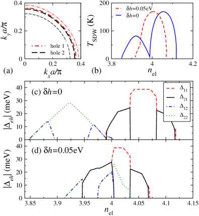
The vs. curves can be understood by examining the evolution of the with at K, plotted in Fig. 3(c) for and in Fig. 3(d) for eV. Note that the values of the pairs and may be swapped at every point. At , the two distinct peaks in Fig. 3(b) correspond to a maximum in for electron doping and in for hole doping. The maximum values are different due to different densities of states in the hole bands. These maxima occur when the area enclosed by the hole Fermi surface is the same as that enclosed by each electron Fermi surface. It is interesting to note that at both maxima a single- state is stable.
When eV, the conditions for and to display a maxima coincide at , as the area enclosed by each hole Fermi surface is almost equal. We hence see a complicated coexistence between the four order parameters: at weak hole doping, all four are non-zero; at weak electron doping, the excitonic instability of the two electron bands involve different hole bands. Although is dominant over most of the doping range, at extreme hole doping a state with only non-zero is realized, corresponding to the weak asymmetry seen in the vs. curve in Fig. 3(b).
Orthorhombic distortion. In all known FeAs parent compounds, the SDW phase occurs only in the presence of an orthorhombic distortion of the crystal. It is found that the stripe-like SDW has its nesting vector oriented along the longer crystal axis. 1111coupling ; 122coupling Here we see how this can be understood within our model on the basis of the effect of the orthorhombic distortion on the Fermi surfaces.
Under an orthorhombic distortion, the energy shift of a state with wave-vector in the unfolded Brillouin zone is where is the strain tensor and we have and . Ziman Note that the wave-vectors in the unfolded Brillouin zone are rotated by 45∘ with respect to the wave-vectors in the crystallographic Brillouin zone. We approximate the energy shifts by their value near the chemical potential, as the Fermi surface shape dominates the physics of our model. The energy shifts of the hole states near the zone centre are therefore neglected, as they will be much smaller than those experienced by the electron pockets. Since the electron pockets are small, we assume that their energy shifts are isotropic. Furthermore, the sign of the energy shift will be opposite for the electron pockets at the X points along the axes of compression (negative energy shift) and dilation (positive energy shift). Ziman We hence model the effect of the orthorhombic distortion by . We compare the electron pockets at eV and in Fig. 4(a).
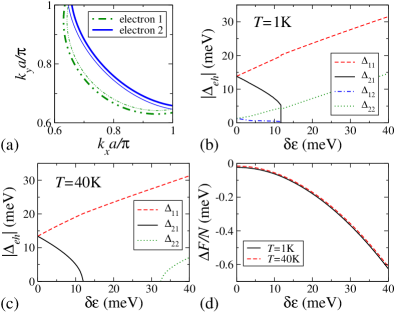
The dependence of the upon at K and K is plotted in Fig. 4(b) and Fig. 4(c), respectively. The effect of is to enhance the pairing between the larger electron and hole pockets () and also the smaller electron and hole pockets (), while suppressing the pairing between the smaller electron (hole) and larger hole (electron) pockets. In analogy to the effect of doping, this can be readily understood as due to the changes in the area enclosed by each electron Fermi surface. Due to the enhanced excitonic pairing, the free energy shows monotonic decrease with increasing , see Fig. 4(d). As the orthorhombic distortion should increase the elastic energy of the lattice, it is therefore possible that the total free energy of the crystal will show a minimum at a non-zero value of the distortion. Deeper investigation of this scenario is left for future work.
The K case shows a large range of where is the only non-zero excitonic average, i.e. the distortion stabilizes a single- SDW state due to the enhanced nesting between the larger electron and hole pockets. In contradiction to experiment, however, the vector is oriented along the shorter crystal axis. This does not necessarily invalidate the excitonic scenario: our model Eq. (1) has equal coupling constants between the different bands. Were hole band 2 to interact more strongly with the electron bands than hole band 1, so that in the undistorted system, the enhancement (suppression) of () by the orthorhombic distortion would likely stabilize a SDW state with the observed vector.
Conclusions. We have presented a mean-field study of the excitonic SDW state for a realistic four-band model of the FeAs parent compounds. We find that the SDW state is sensitively dependent upon the band structure. For a tetragonal unit cell, a two- SDW is realized at ; small changes in the electron pocket ellipticity or the doping, however, stabilize the observed single- state. Varying the relative size of the hole pockets qualitatively changes the vs. curve, agreeing best with experiment when the hole pockets are almost coincident. Kamihara2008 ; 1111coupling The dominant effect of an orthorhombic distortion of the crystal on the band structure was identified as altering the size of the electron pockets. This changes the nesting condition between the Fermi surfaces, and can realize a single- SDW. Our analysis suggests that the electron pockets interact more strongly with the smaller hole Fermi surface than with the larger. We conclude that the excitonic SDW model is capable of qualitatively describing the AF phase of the FeAs parent compounds. The strong sensitivity of the SDW state upon the band structure, however, shows that a quantitative description requires a more detailed understanding of the electronic structure than is currently available.
The authors thank I. Eremin and D. V. Efremov for useful discussions.
References
- (1) Y. Kamihara, T. Watanabe, M. Hirano, and H. Hosono, J. Am. Chem. Soc. 130, 3296 (2008).
- (2) M. Rotter, M. Tegel, and D. Johrendt, Phys. Rev. Lett. 101, 107006 (2008).
- (3) J. Zhao et al., Nature Materials 7, 953 (2008); J. Zhao et al., Phys. Rev. B 78, 132504 (2008).
- (4) Q. Huang et al., Phys. Rev. Lett. 101, 257003 (2008); A. Jesche et al., Phys. Rev. B 78, 180504(R) (2008).
- (5) M. A. McGuire et al., Phys. Rev. B 78, 094517 (2008); M. A. McGuire et al., arXiv:0811.0589 (unpublished).
- (6) W. Z. Hu et al., Phys. Rev. Lett. 101, 257005 (2008).
- (7) S. E. Sebastian et al., J. Phys: Condens. Matter 20, 422203 (2008).
- (8) D. Hsieh et al., arXiv:0812.2289 (unpublished).
- (9) I. I. Mazin, D. J. Singh, M. D. Johannes, and M. H. Du, Phys. Rev. Lett. 101, 057003 (2008)
- (10) D. J. Singh and M.-H. Du, Phys. Rev. Lett. 101, 237003 (2008).
- (11) M. M. Korshunov and I. Eremin, Europhys. Lett. 83, 67003 (2008); Phys. Rev. B 78, 140509(R) (2008).
- (12) T. M. Rice, Phys. Rev. B 2, 3619 (1970).
- (13) Q. Han, Y. Chen, and Z. D. Wang, Europhys. Lett. 82, 37007 (2008).
- (14) A. V. Chubukov, D. Efremov, and I. Eremin, Phys. Rev. B 78, 134512 (2008).
- (15) A. B. Vorontsov, M. G. Vavilov, and A. V. Chubukov, arXiv:0812.2469 (unpublished).
- (16) K. Kuroki et al., Phys. Rev. Lett. 101, 087004 (2008).
- (17) J. Lorenzana, G. Seibold, C. Ortix, and M. Grilli, Phys. Rev. Lett. 101, 186402 (2008).
- (18) Y. Ran et al., Phys. Rev. B 79, 014505 (2009).
- (19) R. Yu et al., arXiv:0812.2894 (unpublished).
- (20) I. I. Mazin and M. D. Johannes, Nature Physics 5, 141 (2009).
- (21) L. V. Keldysh and Y. V. Kopaev, Sov. Phys. Solid State 6, 2219 (1965); J. des Cloizeaux, J. Phys. Chem. Solids 26, 259 (1965).
- (22) Y. V. Kopaev, Sov. Phys. Solid State 12, 1 (1970).
- (23) D. W. Buker, Phys. Rev. B 24, 5713 (1981).
- (24) S. C. Hunter and F. R. N. Nabarro, Proc. Roy. Soc. A 220, 542 (1953).
- (25) J. M. Ziman, Electrons and Phonons (Oxford University Press, Oxford, 1960).