The laser polarization as control parameter in the pattern formation
Abstract
The recently observed dependence of the periodic surface structures on the light polarization in the laser induced pattern formation is analyzed within a model where the polarization induces significant deviation the spatial distribution of the energy deposited by the photon from isotropic energy distribution. We argue that the laser polarization breaks the rotation symmetry on the surface and is responsible for the correlation of the surface structures with the degree and the direction of polarization. Moreover it is shown that the polarization induces the appearence of novel features of the surface morphology and time evolution, which could be directly tested experimentally.
pacs:
74.25The phenomenon of ripple formation on the surfaces of eroded materials is of particular interests due to the large area of application in physical, chemical and material sciences. The development of periodically modulated structures as result of sputtering, the removal of atoms from the surface of solids through the impact of energetic particles (photons or ions), was discovered and studied experimentally nearly three decades ago. The first widely accepted theoretical approach EMMONY ; SIPE describing the periodic surface structures induced by laser radiation suggested that the ripples are the result of interference of incoming laser beam with some form of a surface-scattered electromagnetic wave. In general, this theory was successeful in discription of uniformly distributed patterns with the periodicity dependent from the wavelength of laser radiation and from the angle of incidence.
The development of ultra-short pulses laser technologies and application of femtosecond laser radiation in surface sputtering HENYK has shown that newly rediscovered laser induced periodic surface structures (LIPSS), with lateral periods a few times smaller than the wavelength of the incident light, can not been described in the framework of the conventional LIPSS theory BONSE . Thus, it turns out that the ripple structure has non-trivial surface morphology sharing many similarities with aeolian sand dunes MISBAH , with periodicity independent from laser wavelength and the angle of incidence, but correlated with the local intensity of the laser beam that gives the strong support to the nonlinear self-organized mechanism of formation this structures. In this light the understanding of the puzzling dependence the ripple orientation from the laser polarisation HENYK ; VARLAMOVA where the resulting ripple orientation depends on the direction of the vector of electromagnetic field, become very important and interesting problem.
A revival of interest in the ion induced ripple formation has been caused by successful theoretical prediction BRADLEY the ripple wavelength and orientation in agreement with experimental observations. Further development the nonlinear theory CUERNO ; MAKEEV ; KIM ; CASTRO allowed the proper description the time evolution of the surface morphology under ion-bombardment, ripple stabilization, wavelength dependence with ion energy or flux and production of dot structures as a function of bombardment conditions.
In this we develop a continuum theory of erosion by polarized laser radiation. We exploit connections with ripple formation by ion-beam sputtering and extend this model with inclusion of laser polarization, leading to polarization dependence of coefficients in nonlinear equation of the Kuramoto-Sivashinsky type. Our results suggests that the laser polarization can be very important control parameter.
Following to the Sigmund’s theory of sputtering (SIGMUND, ) we consider the normal erosion velocity at the surface
| (1) |
where is the local correction to the uniform flux due to variation of the local slopes, is a material constant and is the average energy deposited at point O due to the scattering of the photon flux at P
| (2) |
is the total energy carried by the photon flux and , and are the Gaussian distribution widths along x’,y’ and z’ axes, respectively, in the reference frame of the incoming beam. According to Sigmund’s theory the energy distribution widths along axis, respectively, scaled as a - average depth of energy deposition. Obviously, the Gaussian form is not universal and the condition is not a general case, in particular in the case of light interaction with a matter. Whereas the deviations from the Gaussian only slightly modified the pattern formation process FEIX , the asymmetry of energy distribution along surface plain has not been studied yet. One can expect, that the space anisotropy of the energy deposition can be effectively described by the anisotropy of the distribution widths and . Therefore, we except the Gaussian form of energy deposition and consider the laser radiation which penetrates the bulk of the material and stops at some point, where its energy spread out to the neighboring sites (see Fig.1). In order to introduce the polarization in our calculations we choose the vector of electromagnetic field to lie in the x’-z’ plane in the reference frame of the incoming beam. Following to (BRADLEY, ; CUERNO, ) we perform the calculation of erosion rate in the local coordinate system (X,Y,Z) shown in Fig.1.

The local correction to the incident energy flux is now given by , where is the absorption coefficient of the material and is the laser intensity. In order to describe the surface profile in the neighborhood of O we took into account cross-terms of the type
| (3) |
As in (CUERNO, ) we assume that the radii of curvature of the surface are much larger than the penetration depth a SNOS , so that only terms up to first order in and are kept. The integration results in the erosion velocity as a function of angles and the curvatures , and . Next we perform expansions in powers of derivatives of h(x,y,t) and rewrite V in terms of the laboratory coordinates (x,y,h) (CUERNO, ).
| (4) |
We complete Eq. (4) by adding the following physical processes: the surface self-diffusion effects where is the relaxation rate due to thermally activated surface diffusion, together with the fluctuations (short noise) in the flux of the bombarding particles. Finally, we obtain the equation of motion known as an anysotropic noisy Kuramoto-Sivashinsky (KURAMOTO, ) equation where the coefficients are now the complex functions of two angles and . In order to simplify our consideration and because of the reasons discussed below we write here the equation for the case of the normal incident () and in the reference frame rotated by the angle (see Insert Fig.1) that means that and
| (5) | |||||
where the coefficients are given by
| (6) |
and , . Moreover, we neglected here the erosion velocity which does not affect the ripple characteristics, such as ripple wavelength and the ripple amplitude, and can be eliminated by the transformation .
The basic role of the introduced above parameters and can be clarified by means of the linear stability analysis of equation (5).
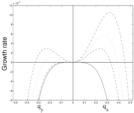
The Fig. 2 shows the linear growth rate along and for various values of and . For the uniform state is stable, whereas for nonzero and the instability sets both along and . An increase of induces the asymmetry in -plain thus for the instability along is suppressed. Thus, the deviation from isotropic energy distribution breaks the rotation symmetry in plain and lids to an anysotropic linear instability. For the sake of definiteness we will fix that corresponds to the condition . From (5) follows that the parameter contributes to the both tension coefficients
| (7) |
One can see that the surface tension coefficients are negative for the normal incidence and in general are not equal to each other due to the fact that the direction of the laser polarization breaks the symmetry along the surface. Consequently, we expect the instability to the ripple formation with wavelength , where i refers to the direction (x or y) along which the associated ( or ) is largest. Thus, in our case of polarization along x-axe for which holds when the ripple structure is oriented in the x direction. Moreover, the ripple wavelength has now the following dependence from
| (8) |
Thus, for the wavelength . The increase of slightly reduces whereas become to be very large for (linear polarization along x axis). The inset of Fig.2 shows the relation . Thus, the parameter and the angle allow us to change the orientation and topology of ripples that means that the parameter is a control parameter which we will call in the following the degree of polarization. We will consider three cases: (i) circular polarization, (); (ii) linear laser polarization, (), and (iii) elliptic polarization, ().
Another quantity which can change the orientation of ripple is incidence angle . Thus, for angles less than a critical angle , the wave vector of the modulations is parallel to the component of the beam in the surface plane BRADLEY .
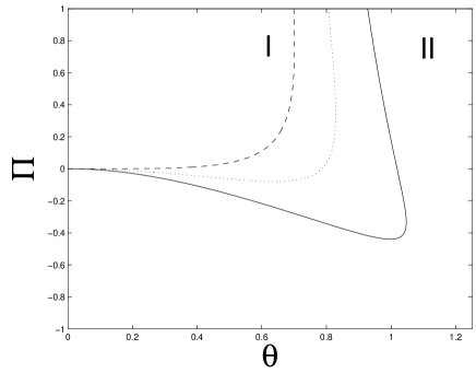
By this means the orientation of ripple due to polarization and due to incoming angle can compete or work together. Fig. 3 displays the ripple orientation phase diagram () for three values of parameter (negative values of correspond to the vector E along y axis). The boundary is defined by and separates the region I () and region II (). In the case of (circular polarization) and the normal incidence of laser beam the dot structures are expected in our model. The increase of for small aligned the ripples along the vector . Whereas the growth of can still change the direction of ripple for at some , which depends from , the laser polarization completely suppress the transition for negative . The interesting result, which can be tested experimentally, is the possible reorientation of ripple in the case of weak polarization for . In any case, one have to perform detailed experimental investigation the angle dependence for various values of in order to fix the parameter . Moreover, our model allows us to understand the nature of LIPPS which are oriented parallel to the laser p-polarization at a relatively large incident angle. Nevertherless, we have to note here that our approximation may be not valid for the large angles of the incidence where the effects of interaction of laser radiation with the material surface can not be neglected. Therefore, we limit ourselves in the following to the presentation of our results only for the normal incidence of laser beam and set . The dependence of ripples structures on the angle of the incidence for large will be discussed somewhere else.
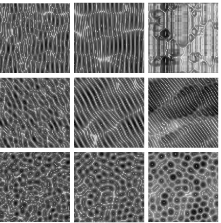
Having analyzed the linear regime we now precede by investigating the influence of nonlinear terms and . As shown early (PARK, ), there is a clear separation of the linear and the nonlinear behaviour in time in such way that in the linear regime up to a crossover time the nonlinear terms as would be absent whereas the nonlinear terms take over after and completely determine the surface morphology which depends on the relative signs of and . For our choice both and are negative and depend from , that means the disappearance of ripples above , which is decreased with increasing of and the appearance of kinetic roughening.
The surface morphologies obtained by numerically integrating the equation (5) for various values of , and time show in Fig.4 that the anisotropy in the energy deposition can describe the correlation of ripple orientation with laser polarization and saturation of ripples with increasing of time. However, in spite of remarkable concurrence the calculated and the ablated surfaces VARLAMOVA , a direct comparison with experimental date is difficult because the relevant mechanism which is responsible for the energy anisotropy is still under discussion. Whereas in metalls and semiconductors the incident laser radiation can excite the plasma wave in the electron plasma produced by multiphoton ionization SHIMOTSUMA , the electron density in dielectrics is too low for the intensities near the damage threshold. Instead, it was proposed, that the femtosecond laser pulses could induce high inhomogeneous ionization under laser radiation inside the transparent solids and the dielectrics, forming nano-droplets of plasma by means of the ”forest-fire” multiphoton and avalanche ionization GAIER . Interaction of infrared laser radiation with nano-plasma-dielectric composites can excite the surface plasmons polaritons (SPP) in the nano-particles and induce the giant enhancement of local electric fields. In contrast to BHARDWAJ , where the underdense nanoplasmas grows into nanosheets orientated with their normal parallel to the laser polarization, we consider the energy deposition along the laser polarization due to the powerflow distribution an oblate nanoparticle BASHEVOY . Thus, the concentration of the powerflow along the vector of electromagnetic field near the nano-particles leads to the local instability of the lattice that could bring a collapse of the atomic structure about. We think that the surface atoms of such annealed areas have a good chance to be sputtered at the time scale of electron-phonon relaxation.
In summary, we have shown that the correlation of ripples orientation with laser polarization can be consistently described within a model where the polarization induces an anisotropy in the energy distribution and causes the symmetry break on the surface. The model accounts for experimental features of laser induced surface modulations and leads to the numerous predictions which can be directly tested experimentally. Moreover, our results support the nonlinear self-organized mechanism of formation the ripples on the surface of solids. However, a more detailed investigation of the effective mechanism which is responsible for the anisotropy of energy transfer remains an interesting issue for future work.
References
- (1) D.C. Emmony et al., Appl. Phys. Lett 23, 598 (1973).
- (2) J.E. Sipe et al., Phys. Rev. 27, 1141 (1983).
- (3) M. Henyk et al., Appl. Phys. A: Mater. Sci. Process. 69, 355 (1999); J.Bonze et al., Appl. Phys. A: Mater. Sci. Process. 71, 657 (2000); A. Borowies and H. K. Haugen, Appl. Phys. Lett. 82, 4462 (2003).
- (4) J. Bonse et al., J. Appl. Phys. 97, 013538 (2005).
- (5) C.Misbah and A.Valance, Eur. Phys. J. E 12, 523 (2003).
- (6) F.Costache et al., Appl. Surf. Sci. 186, 352 (2002); O.Varlamova et al., Appl. Surf. Sci. 252, 4702 (2006).
- (7) R.M. Bradley and J.M.E. Harper, J. Vac. Sci. Technol. A 6, 2390 (1988).
- (8) R. Cuerno and A.-L. Barabási, Phys. Rev. Lett. 74, 4746 (1988).
- (9) M.A.Makeev et al., Nucl. Instr. and Meth. in Phys. Res. B, 197, 185 (2002).
- (10) T.C.Kim et al., Phys. Rev. Lett. 92, 246104 (2004).
- (11) M.Castro et al., Phys. Rev. Lett. 94, 016102 (2005).
- (12) P. Sigmund, Phys. Rev. 194, 383 (1969).
- (13) M. Feix et al., Phys. Rev. B 71, 125407 (2005).
- (14) Y. Shimotsuma et al., Phys. Rev. Lett. 91, 247405 (2003)
- (15) L.N. Gaier et al., J. Phys. B 37, L57 (2004).
- (16) V.R. Bhardwaj et al., Phys. Rev. Lett. B 96, 057404 (2006).
- (17) M.V. Bashevoy et al., Optics Express 13, 8372 (2005).
- (18) This penetration depth is differ from the real penetration depth and means the distance from the surface to the bulk, at which the scattering of light in nano-plasmas have influence on the surface atoms.
- (19) Y. Kuramoto and T. Tsuzuki, Prog. Theor. Phys. 55, 356 (1977); G.I. Sivashinsky, Acta Astronaut. 6, 569 (1979).
- (20) S.Park et al., Phys. Rev. Lett. 83, 3486 (1999).
- (21) S.Facsko et al., Phys. Rev. B 69, 153412 (2005).