Anisotropic magneto-transport effects at SrTiO3LaAlO3 interfaces
Abstract
The resistivity as a function of temperature, magnetic field and its orientation for atomically flat SrTiO3LaAlO3 interfaces with carrier densities of 31013 cm-2 is reported. At low magnetic fields superconductivity is observed below 130mK. The temperature dependence of the high field magnetoresistance and its strong anisotropy suggest possible magnetic ordering below 35K. The origin of this ordering and its possible relation to superconductivity are discussed.
pacs:
75.70.Cn, 73.40.-cInterface between strongly correlated electron materials can be very different from their constituents. It has been shown that if LaAlO3 is epitaxially grown on TiO2-terminated SrTiO3 a two dimensional electron gas is formed at the interface between these insulators Ohtomo and Hwang (2004). This interface was latter shown to be superconducting Reyren et al. (2007) and magnetic Brinkman et al. (2007). Recently Caviglia et al. have shown that the superconducting transition temperature can be controlled by solely varying the number of charge carriers at the interface using a gate voltage.Caviglia et al. (2008) These unexpected results and the potential for development of high performance oxide based electronics motivated an effort to understand the properties of this interface Willmott et al. (2007); Herranz et al. (2007); Zhong and Kelly (2008) and to improve it.
The origin of the large carrier concentration at the interface remains under debate. When depositing monolayers of LaAlO3 on SrTiO3 conductivity appears only for a TiO2 terminated surface Ohtomo and Hwang (2004) at a threshold of 4 unit cells.Thiel et al. (2006) These observations suggest that the electrostatic structure of the interface: nonpolar SrTiO3 planes covered with alternatingly charged planes on the LaAlO3 side should lead to an interfacial reconstruction. This reconstruction can be dominantly electronic in nature,Okamoto and Millis (2004); Popović et al. (2008) or partly due to cationic mixing.Willmott et al. (2007) A lattice distortion driven by the polar nature of the interface has also been proposed.Pentcheva and Pickett (2009) Other papers suggested that oxygen vacancies play a major role in creating high carrier densities. Kalabukhov et al. (2007); Herranz et al. (2007); Siemons et al. (2007) It seems that the latter effect is insignificant for samples deposited at pressure range of to Torr.Nakagawa et al. (2006); Reyren et al. (2007); Huijben et al. (2006)
Magnetic effects have been theoretically predicted for SrTiO3LaAlO3 interfaces.Zhong and Kelly (2008); Pentcheva and Pickett (2006) Recent observations of magnetic hysteresis below 0.3K along with magneto-resistance oscillations with periodicity proportional to have been explained in terms of commensurability of states formed at the terrace edges of the SrTiO3 substrate.van Zalk et al. (2008)
While superconductivity in this interface has been shown to be two dimensional in nature Reyren et al. (2007) the way such interface can exhibit magnetic properties is still a puzzle. In this paper we show that for carrier concentrations of the two dimensional electron gas is superconducting at 130mK, yet, novel magneto-transport effects are observed below 35K. Our data support possible evidence for a magnetic order formed below this temperature. A magnetic impurities scenario is ruled out.
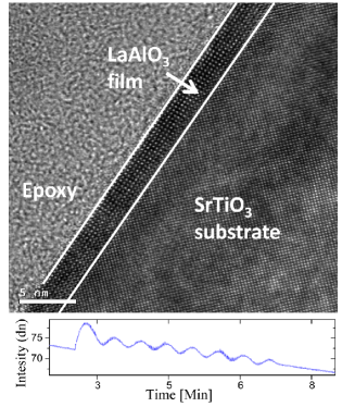
Eight unit cells of LaAlO3 were deposited from a single crystal target onto a TiO2-terminated SrTiO3 prepared in a similar way as described by Koster et al. Koster et al. (1998) by pulsed laser deposition. We use pulse rate of 1Hz and energy density of 1.5 Jcm-2 at oxygen pressure ranging between 1 - 5 Torr and temperature of . The deposition was monitored by reflection high energy electron diffraction (RHEED). The maxima of the RHEED intensity oscillations indicate a complete layer formation and used as a measurement for the sample thickness (see Fig. 1b.). One of the samples was imaged by a high resolution transmission electron microscope revealing a high quality interface and confirming the thickness measurement by the RHEED (see Fig. 1a.). The two dimensional electron gas underneath the LaAlO3 layers was electrically connected using a wire bonder. One of the samples was patterned using reactive ion etch (RIE) into Hall bars with bridges dimensions of 50*750 microns squared. The bridges were align perpendicular or parallel to the terrace edges. Other samples were connected in a Van-Der Pauw (VDP) geometry for resistivity and Hall measurements, or in a strip geometry (with dimensions of about ) when the current direction had to be well defined.
In this paper we present four typical samples deposited at oxygen pressures of (Sample 1), (Samples 2 and 4) and (Sample 3), with carrier concentrations of , , and for samples 1-4 respectively as inferred from Hall measurements at 2K. The charge carrier density has a very weak temperature dependence up to 100K. This is in contrast with the strong temperature dependence reported in Ref.Brinkman et al. (2007).
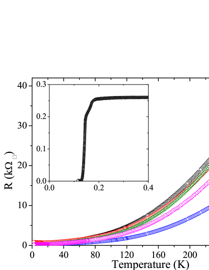
The sheet resistance as a function of temperature for these samples is shown in Fig. 2. All samples under study including all bridges in the patterned sample exhibit similar transport properties. The fact that small bridges and VDP measurements resulted in similar features is indicative of the samples’ homogeneity. We also note that the variation of oxygen pressure during deposition resulted in a rather small change in carrier concentration and resistivity. Sample 1 was also measured in a dilution refrigerator and was shown to be superconducting with the transition temperature Tc=130mK (see insert of Fig.2).
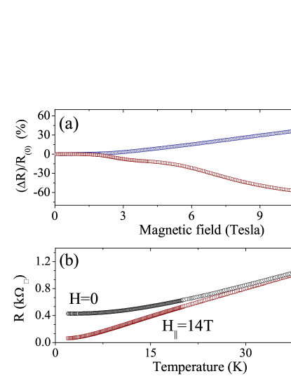
The magnetoresistance (MR) is defined as , where R(H) is the resistance at a magnetic field H. It is presented for T=2K (Sample1) in Fig. 3(a). When the field is applied perpendicular to the film a positive MR is observed (blue circles). The data is an average between positive and negative fields in order to eliminate spurious Hall contribution due to contact misalignment. By contrast a large negative MR is seen for fields parallel to the film and to the current (red squares). We note that both the positive and negative MR are very large, 50% and 70% respectively for a magnetic field of 14 Tesla. We also note that for perpendicular fields no hysteresis is observed down to 130mK where superconductivity shows up.
In Fig. 3(b)we show the temperature dependence of the (parallel) negative MR (Sample1). The black circles are the zero field measurement and the red circles are data taken at 14 Tesla applied parallel to the current. We emphasize that the negative MR disappears above 35K. The large negative MR and its strong anisotropy suggest strong magnetic scattering in the plane. To further investigate this assumption we rotated the field around a horizontal axis changing its angle with the normal to the interface while keeping the field’s amplitude constant (14 Tesla).
In Fig. 4 the MR for sample2 at 14 Tesla is plotted as a function of the angle between the magnetic field and the normal to the film (see insert for illustration). corresponds to a magnetic field applied parallel to the current. The dip is extremely sharp (see insert for the entire angle scan) and the MR changes sign at (or ).
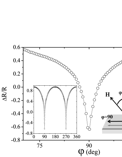
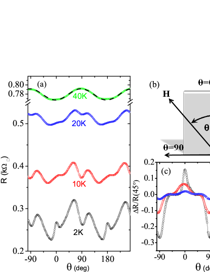
We shall now check for anisotropy in the plane of the interface. In Fig.5 the resistance as a function of angle between the magnetic field and the current is shown for various temperatures (Sample3). corresponds to a magnetic field applied parallel to the film and perpendicular to the current (see illustration Fig.5(b)). At 40K the resistance is maximum for a field perpendicular to the current. The dashed black line Fig.5(a) is a fit using , with being the angle between the field and the current, and . This simple dependence persists up to above 100K. As elaborated in the discussion below we attribute this behavior to geometric effects related to the two dimensional nature of the electron gas at the interface.
Below 40K another effect appears. Focusing for example on the 20K data, a dip appears at while a peak is revealed at 0, . At 10K and below the latter effect becomes even larger than the and a significant maxima (minima) appears at and ( and ). We note that since the interface is probably not perfectly parallel to the field a small Hall contribution results in a small deviation between zero and Moreover such a small deviation can result in a perpendicular component, although this component is minute its influence can be non-negligible and should add-up to the effect. To eliminate the Hall contribution we symmetrized the data for positive and negative fields. To remove the contributions with the dependencies we subtracted the fit from the 2K, 10K and 20K data and were determined for each temperature. This procedure uncovers the (in-plane) anisotropic magnetoresistance . The resulting data normalized with the measured resistance at are shown in Fig.5(c). We note a sharp peak when the field is parallel to the current and a sharp dip appears when the field is applied perpendicular to it. A similar effect is seen for a different strip rotated by 90 degrees (not shown). As elaborated below we interpret this effect as being the anisotropic MR. A small deviation between the angles at which the maximum appears for various temperatures could be due to different angular sweep direction and the rotator backlash.
We shall now discuss the MR data from Figs.3, 4, 5. We first note that the amplitudes of both negative and positive MR in Fig.3a. are very large. The positive MR for a field perpendicular to the interface could be due to orbital effects that have a significant contribution since is close to unity, where is the cyclotron frequency and the scattering time. For a field parallel to the current such orbital effects are not existent. Yet, the MR is even larger, 70%. The relevant mechanisms that can produce negative MR are: two dimensional (2D) weak localization, magnetic impurities and the magnetic nature of the material itself. The first effect is ruled out since it is usually small (of the order of a few percents) and appears for field applied perpendicular to the film. The second effect is usually isotropic, in strong contrast with our results. We are therefore led to conclude that the large negative MR we observe is due to a magnetic order formed at the interface.
We emphasize that the negative MR seen in Fig.3a. for is very different from the negative isotropic MR reported in Ref.Brinkman et al. (2007). The MR versus dependance shown in Fig.4 is extremely sharp around . This is a key observation in our paper. The fact that the MR changes sign for a variation of implies that a small perpendicular field component is sufficient to mute the mechanism responsible for the parallel negative MR. This is due to the fact that when the parallel field component is almost unchanged (13.98 Tesla) while the perpendicular component is only 0.73 Tesla. Such a component is too small to induce any orbital effect as can be seen in Fig.3a. One may claim that the positive orbital MR for 0.73 Tesla is in fact larger, yet overwhelmed by a large isotropic negative MR. However, when measuring the negative MR with a parallel field of 0.73 Tesla we find it to be very small (see . Hence this scenario is ruled out. We therefore conclude that there is a strong strange anisotropy of the MR. The only element in our system with such strong directionality is the interface itself. We therefore conclude that the strong dependence gives possible evidence for the existence of magnetic order confined to a few layers near the interface. This magnetic order in the interface vanishes above 35K according to the data in Fig.3b. for the carrier density and LaAlO3 thickness under study.
Further evidence for the quasi-2D nature of the conducting interface can be found from the in-plane angular dependence of the MR as presented in Fig.5 at 40K. For this geometry (field and current in plane) the Lorentz force is perpendicular to the interface. Assuming a quasi 2D confinement one expects an enhancement of scattering as the field is applied perpendicular to the current assuming that the band structure is not very simple. This positive orbital contribution to the MR should be quadratic in the field component that is perpendicular to the current. We observed a behavior as expected (see dashed line Fig.5).
We can roughly estimate the width of the confinement zone using a naive calculation with the mean free path at low temperatures at 2K, the Fermi wave number , the electron charge, the sheet resistance, and the carrier density. The ratio between this MR and the one observed when the field is applied perpendicular to the interface should be proportional to where is the size of the confinement zone. Substituting the values for and the amplitude of the two orbital effects at 40K we obtain . This gives the right order of magnitude for the width of the confinement zone. We note that this effect and all other effects reported here are similar for current running parallel or perpendicular to the substrate terraces, which rules out the terraces as their origin in contrast with ref.van Zalk et al. (2008).
In summary, we have deposited sharp SrTiO3 LaAlO3 interfaces. We studied the temperature field and orientation dependence of the MR. We identify four contributions to the MR: (a) an orbital one, measured when the field is perpendicular to the interface, (b) the MR persisting up to rather high temperatures. This MR appears when the field is applied parallel to the interface and perpendicular to the current. We relate it to the finite size of the confinement zone. This MR is also positive, but its amplitude comparing to the previous effect is smaller by a factor proportional to . (c) The more interesting MR appears below 35K. This, negative, low temperature MR appears when the field is applied exactly parallel to the interface and to the current. It cannot be due to orbital effects and its large (negative) magnitude suggests that it has a magnetic origin. (d) the last effect is seen when rotating the field in plane. Below 35K anisotropic MR appears. It has a maximum for (parallel to the current). Its amplitude increases as the temperature decreases. We interpret this MR as being the anisotropic MR expected for magnetic materials.McGuire and Potter (1975) Scattering resulting from spin-orbit interactions becomes stronger when the electron travels parallel to the magnetization as seen in Fig.5(c). The latter two effects: the strong (parallel) negative MR and the anisotropic, in-plane MR show up together below 35K. Below this temperature a magnetic phase emerges. This phase is extremely sensitive to an out of plane magnetic field. This sensitivity is unclear to us, yet, it rules out magnetic impurities as the origin of the effects and suggests that the magnetic order is confined to the vicinity of the interface. We take note of the following observations: both the parallel negative MR and the anisotropic, in-plane MR exhibit no saturation up to 14 tesla, and we were not able to observe magnetic hysteresis down to Tc=130mK. In view of these observations and due to the occurrence of superconductivity at low temperatures it is difficult to believe that the interface is ferromagnetic. We speculate that antiferromagnetic order is formed at the interface below a Nèel temperature of 35K. this temperature may vary with number of charge carriers and film thickness. Providing that this antiferromagnetism is not induced by the applied field this system could be another example of coexistence of antiferromagnetism and superconductivity as in heavy fermion materials Mathur et al. (1998) and in some of the cuprates.Dagan et al. (2004)
Acknowledgements.
We thank A. Aharony, G. Deutscher, A. Gerber, S. Hacohen-Gourgy, O. Entin-Wohlman and Y. Yacoby for useful discussions. This research was partially supported by the Israel Science Foundation (ISF) by the FIRST program of the ISF by the Binational Science Foundation and by the Wolfson family charitable trust. CWT is grateful for the financial support by Grant No. 29637 from European Commission.References
- Ohtomo and Hwang (2004) A. Ohtomo and H. Y. Hwang, Nature (London) 427, 423 (2004).
- Reyren et al. (2007) N. Reyren et al., Science 317, 1196 (2007).
- Brinkman et al. (2007) A. Brinkman et al., Nature Mater. 6, 493 (2007).
- Caviglia et al. (2008) A. D. Caviglia et al., Nature (London) 456, 624 (2008).
- Willmott et al. (2007) P. R. Willmott et al., Phys. Rev. Lett. 99, 155502 (2007).
- Herranz et al. (2007) G. Herranz et al., Phys. Rev. Lett. 98, 216803 (2007).
- Zhong and Kelly (2008) Z. Zhong and P. J. Kelly, Europhys. Lett. 84, 27001 (2008).
- Thiel et al. (2006) S. Thiel et al., Science 313, 1942 (2006).
- Okamoto and Millis (2004) S. Okamoto and A. J. Millis, Nature (London) 428, 630 (2004).
- Popović et al. (2008) Z. S. Popović, S. Satpathy, and R. M. Martin, Phys. Rev. Lett. 101, 256801 (pages 4) (2008).
- Pentcheva and Pickett (2009) R. Pentcheva and W. E. Pickett, Phys. Rev. Lett. 102, 107602 (2009).
- Kalabukhov et al. (2007) A. Kalabukhov et al., Phys. Rev. B 75, 121404 (2007).
- Siemons et al. (2007) W. Siemons et al., Phys. Rev. Lett. 98, 196802 (2007).
- Nakagawa et al. (2006) N. Nakagawa, H. Y. Hwang, and D. A. Muller, Nature Mater. 5, 204 (2006).
- Huijben et al. (2006) M. Huijben et al., Nature Mater. 5, 556 (2006).
- Pentcheva and Pickett (2006) R. Pentcheva and W. E. Pickett, Phys. Rev. B 74, 035112 (2006).
- van Zalk et al. (2008) M. van Zalk et al., arXiv:0806.4450v1 (2008).
- Koster et al. (1998) G. Koster et al., Appl. Phys. Lett. 73 (1998).
- McGuire and Potter (1975) T. R. McGuire and R. I. Potter, IEEE Trans. Magn 11, 1018 (1975).
- Mathur et al. (1998) N. D. Mathur et al., Nature 394, 39 (1998).
- Dagan et al. (2004) Y. Dagan et al., Phys. Rev. Lett. 92 (2004).