Dislocation core energies and core fields from first principles
Abstract
Ab initio calculations in bcc iron show that a screw dislocation induces a short range dilatation field in addition to the Volterra elastic field. This core field is modeled in anisotropic elastic theory using force dipoles. The elastic modeling thus better reproduces the atom displacements observed in ab initio calculations. Including this core field in the computation of the elastic energy allows deriving a core energy which converges faster with the cell size, thus leading to a result which does not depend on the geometry of the dislocation array used for the simulation.
pacs:
61.72.Lk, 61.72.BbPlastic deformation in crystals is heavily related to the dislocation core properties Hirth and Lothe (1982). As experimental investigation of the dislocation core is difficult, atomic simulations have become a common tool in dislocation theory. But dislocations induce a long-range elastic field and one has to take full account of it in the atomic modeling. This is even more crucial for ab initio calculations because of the small size of the unit cell that can be simulated. In this Letter, we illustrate this point for the screw dislocation in bcc Fe by showing that the commonly-used elastic description, i.e. the Volterra solution Hirth and Lothe (1982), has to be enriched in order to get quantitative information from ab initio calculations.
Two different methods based on ab initio calculations have been developed to model dislocations. In the first approach, a single dislocation is introduced in a unit cell which is periodic only along the dislocation line and with surfaces in the other directions. Surface atoms are displaced according to the dislocation long-range elastic field and can be either kept fixed or relaxed using lattice Green functions Woodward and Rao (2001). The main drawback of this method is that, in ab initio calculations, one cannot separate the energy contribution of the dislocation from the surface one. To calculate dislocation energy properties, one has to use the second approach which is based on full periodic boundary conditions Ismail-Beigi and Arias (2000); Frederiksen and Jacobsen (2003); Blase et al. (2000); Cai et al. (2001). As this is possible only if the total Burgers vector of the unit cell is zero, a dislocation dipole is simulated. Using elasticity theory, one can calculate the interaction between the two dislocations forming the dipole as well as with their periodic images Cai et al. (2001), and thus isolate dislocation intrinsic properties.
We use this dipole approach to study the core properties of screw dislocations in bcc iron with ab initio calculations based on density functional theory using the SIESTA code as described in Ref. Ventelon and Willaime, 2007. The dislocations are positioned at the center of gravity of three neighboring atomic columns. Depending on the sign of the Burgers vector compared to the helicity of the original site, there are two different configurations, termed “easy” and “hard”. The “hard” core configuration shifts locally the atoms such that they lie in the same plane. From steric considerations, one thus expects this configuration to be less stable. The energy landscape experienced by the gliding dislocation is dictated by the energy difference between these two configurations which is a maximum for the Peierls barrier. It is therefore important to get a precise knowledge of the corresponding core energies.
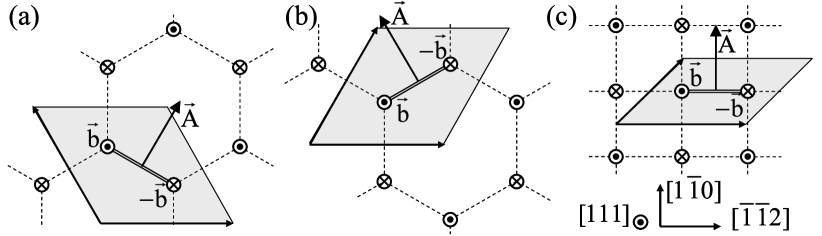
We introduce the dipole in periodic unit cells corresponding to different dislocation arrays Ventelon and Willaime (2007). The triangular arrangements of Figs. 1a and 1b preserve the 3-fold symmetry of the bcc lattice in the direction. One can obtain two variants which are related by a rotation. We refer to them as the twinning (T) (Fig. 1a) and the anti-twinning (AT) triangular arrangement (Fig. 1b) EndNote2 . The last dislocation arrangement (Fig. 1c) is equivalent to a rectangular array of quadrupoles.

Simulation unit cells are built so that the two dislocations composing the dipole are in the same configuration, either “easy” or “hard” depending on the sign of the Burgers vector. Assuming that the elastic displacement field created by each dislocation corresponds to the Volterra one Hirth and Lothe (1982), the elastic energy stored in the simulation box is proportional to the square of the Burgers vector and therefore is the same for the “easy” and “hard” configurations. The core energy difference between the two possible configurations is thus simply given by half the energy difference obtained from ab initio calculations for the same unit cell. This energy difference is shown as solid symbols in Fig. 2. The result depends on the chosen dislocation arrangement. According to the T triangular arrangement, the “hard” core configuration is more stable than the “easy” one, whereas the quadrupolar and the AT triangular arrangements lead to the opposite conclusion. For a given arrangement, the convergence with the number of atoms is proportional to . The computational cost to directly deduce converged values from ab initio calculations is therefore out of reach.
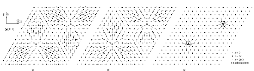
To understand how our simulation approach has to be enriched to lead to unambiguous dislocation core energies, we examine the atom displacements created by the dislocation array in ab initio calculations. For all unit cells, atom displacements in the direction, i.e. the screw component, correspond to dislocations having a symmetrical and compact core structure, in agreement with recent ab initio calculations in bcc Fe Frederiksen and Jacobsen (2003); Domain and Monnet (2005); Ventelon and Willaime (2007). The screw dislocation dipoles also create displacements in the plane, i.e. perpendicular to the screw axis (Fig. 3a). Part of this edge component arises from elastic anisotropy. Nevertheless, when subtracting the displacements predicted by anisotropic elasticity for the periodic dislocation array Cai et al. (2001) from the ones given by ab initio calculations, one obtains a residual displacement (Fig. 3b) which looks like a combination of 2-dimension expansions centered at the dislocations.
This is not included in the Volterra solution describing the dislocation elastic field. Nevertheless, going back to the seminal paper of Eshelby et al. Eshelby et al. (1953), it appears that a dislocation can also lead to such a supplementary elastic field. Indeed, Eshelby et al. showed that a straight dislocation in an infinite elastic medium creates in a point defined by its cylindrical coordinates and a displacement given by a Laurent series which leading terms are
| (1) |
Usually, only the two first terms of this series are considered leading to the well-known Volterra solution Stroh (1958). This gives the long-range displacement induced by the discontinuity along the dislocation cut.
Close to the dislocation core, the third term in Eq. 1 may be relevant too Gehlen et al. (1972); Henager and Hoagland (2005). This corresponds to what is usually called the dislocation core field. Such a field arises from non-linearities in the crystal elastic behavior and from perturbations due to the atomic nature of the core. It can be modeled within anisotropic linear elasticity theory using line-force dipoles representative of an elliptical line source expansion located close to the dislocation core Hirth and Lothe (1973). The core field is then characterized by the first moments of this line-force distribution. We propose in the following an original approach that allows to directly deduce the moments from quantities that can be “measured” in atomic simulations.
In that purpose, we consider the elastic energy of a periodic unit cell containing a dislocation dipole defined by its Burgers vector and its cut vector . Each dislocation also creates a core field corresponding to the moments given by the second-rank tensor . An homogeneous strain can be superposed to the heterogeneous strain created by the dislocation dipole. This contributes to the elastic energy by an amount Bacon et al. (1980)
| (2) |
where is the area of the simulation unit cell perpendicular to the dislocation lines, the corresponding height and the elastic constants. The homogeneous stress is defined as
| (3) |
with the stress-free strain
| (4) |
where the elastic compliances are the inverse of the elastic constants.
When the dislocations do not create any core field (), one recovers the fact that the elastic energy is minimal for an homogeneous strain equal to the plastic strain produced when the dislocation dipole is introduced in the simulation unit cell Cai et al. (2001). The core fields induce a second contribution which is proportional to the dislocation density, thus allowing to define a dislocation formation volume. Our ab initio calculations lead for a screw dislocation in bcc iron to a dilatation perpendicular to the dislocation line, Å2, and to a contraction along the dislocation line, Å2, where the formation volumes are defined per unit of dislocation line.
Instead of letting the unit cell relax its size and shape, one can also keep fixed the periodicity vectors and minimize the energy only with respect to the atomic positions. The simulation box is thus subject to an homogeneous stress from which the moments responsible for the dislocation core field can be deduced using Eqs. 3 and 4. The component of the “measured” homogeneous stress is negligible compared to and , in agreement with the following argument.
For a screw dislocation in a cubic crystal, because of the 3-fold symmetry, the tensor is diagonal with and if the unit vector corresponds to the direction. The core field is thus a pure dilatation in the plane. This is true when the dislocation is in a stress-free state or if the stress experienced by the dislocation also obeys this 3-fold symmetry. The ab initio calculations indeed lead to such a tensor for the two triangular arrangements. The quadrupolar arrangement induces a stress which does not obey this symmetry. Because of the moment polarizability EndNote3 , we obtain different values for and in this case. Nevertheless, all dislocation arrangements used in ab initio calculations converge with the cell size to GPa.Å2 for both “easy” and “hard” core configurations. As for the contraction observed along the dislocation line, it arises from the elastic compliance which couples the strain component with the force moments and .
Knowing the moments, we model the dislocation elastic displacement as the superposition of the Volterra and the core fields. We can thus compare the displacement given by ab initio calculations with the one predicted by elasticity theory for the dislocation periodic array Cai et al. (2001). Looking at the difference between the fields given by the two modeling techniques for the in-plane component (Fig. 3c), one sees that elasticity theory perfectly manages to reproduce the displacement given by ab initio calculations, except for atoms which are too close to the dislocation cores. It is clear that the superposition of the core field to the Volterra solution greatly improves the description of the dislocation elastic field.
The excess energy , i.e. the energy difference per unit of height between the unit cell with and without the dislocation dipole, is the sum of the two dislocation core energies and of the elastic energy.
| (5) |
where and are definite positive tensors which only depend on the elastic constants. contains the elastic interaction between the two dislocations composing the primary dipole, as well as the interaction with their periodic images. The core fields modify this interaction energy as the dislocations now interact not only through their Volterra elastic fields but also through their core fields and the combination of these two elastic fields. The last term in Eq. 5 corresponds to the increase of the dislocation self elastic energy due to their core fields. The cutoff distance is introduced because elastic fields are diverging due to elasticity inability to describe atom displacements in the dislocation core. The core energy that can be deduced from atomic simulations therefore depends on the value of .
We use Eq. 5 to extract dislocation core energy from atomic simulations: and are deduced from ab initio calculations, whereas , , and are calculated with anisotropic elasticity theory. A core radius slightly larger than the Burgers vector ( Å) leads to reasonable core energies and a good convergence with the size of the simulation unit cell. The core energy difference between the “easy” and the “hard” core configurations of the screw dislocation in bcc iron converges now rapidly to a value which does not depend on the geometry of the dislocation arrangement (Fig. 2). For all simulations, the “easy” core configuration is more stable than the “hard” one, with a core energy converging respectively to meV.Å-1 and meV.Å-1.
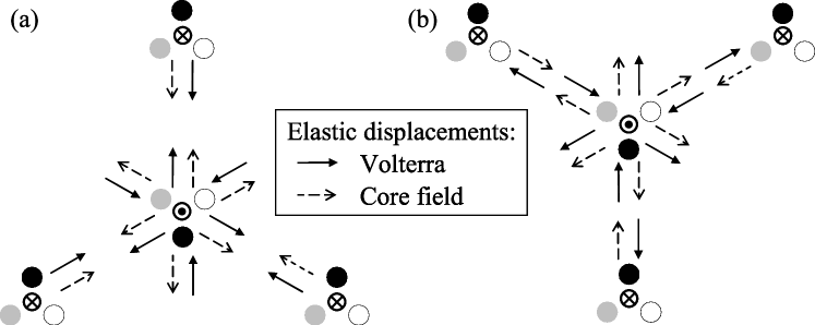
We can now understand why the simple approach, where only the Volterra elastic field is considered, leads to core energies which strongly depend on the geometry of the dislocation array. Looking at the in-plane displacement created by each component of the dislocation elastic field, the Volterra part oscillates as a function of between a compression and a tension type, whereas the core-field only leads to a compression. This is illustrated in Fig. 4 for the two variants of the triangular arrangement with the dislocations in their “easy” core configuration. It is clear on this figure, that the effects of the Volterra and the core fields will sum up in the regions between two neighboring dislocations for the T variant (Fig. 4a), whereas they will partially compensate for the AT variant (Fig. 4b). One thus expects a stronger elastic interaction between dislocations for the T variant than for the AT one. This is the opposite for the “hard” core configuration, as changing the sign of the Burgers vector reverses the Volterra elastic field without modifying the core field. When neglecting the dislocation core field, one thus overestimates the elastic energy difference between the “easy” and “hard” core configurations for the T variant and underestimates it for the AT one. On the other hand, the coupling of the Volterra and the core elastic field leads to a negligible interaction between neighboring dislocations for the quadrupolar arrangement because of its centro-symmetry. This arrangement actually appears as the best-suited one to extract quantitative information from atomic simulations Cai et al. (2001).
This dilatation due to the dislocation core field is not specific to iron. When analyzing previous ab initio calculations Ismail-Beigi and Arias (2000); Frederiksen and Jacobsen (2003) we can conclude that screw dislocations exhibit a similar core field in other bcc metals like Mo and Ta. On the other hand, empirical potentials may fail to predict such a core dilatation. This is the case for Mendelev potential Mendelev et al. (2003) which is often used to study dislocations in iron Domain and Monnet (2005); Chaussidon et al. (2006); Clouet et al. (2008).
In addition to determining the formation volume of the screw dislocation in iron and modeling it within anisotropic linear elasticity theory, our study shows that considering this core field is crucial when deriving from atomic simulations dislocation parameters like their core energy. This supplementary elastic field should also influence any energy differences, like the Peierls barriers, and stresses extracted from atomic simulations. Moreover, because of the formation volume associated with this core field, a dislocation can interact with an hydrostatic stress. Close to the core, it will modify the dislocation interaction with point defects Clouet et al. (2008).
Acknowledgements.
This work was supported by the European Fusion Materials Modeling program and by the SIMDIM project under contract ANR-06-BLAN-250.References
- Hirth and Lothe (1982) J. P. Hirth and J. Lothe, Theory of Dislocations (Wiley, New York, 1982), 2nd ed.
- Woodward and Rao (2001) C. Woodward and S. I. Rao, Philos. Mag. A 81, 1305 (2001); Phys. Rev. Lett. 88, 216402 (2002).
- Ismail-Beigi and Arias (2000) S. Ismail-Beigi and T. A. Arias, Phys. Rev. Lett. 84, 1499 (2000).
- Frederiksen and Jacobsen (2003) S. L. Frederiksen and K. W. Jacobsen, Philos. Mag. 83, 365 (2003).
- Blase et al. (2000) X. Blase et al., Phys. Rev. Lett. 84, 5780 (2000).
- Cai et al. (2001) W. Cai et al., Phys. Rev. Lett. 86, 5727 (2001); Philos. Mag. 83, 539 (2003); J. Li et al., Phys. Rev. B 70, 104113 (2004).
- Ventelon and Willaime (2007) L. Ventelon and F. Willaime, J. Computer-Aided Mater. Des. 14, 85 (2007).
- (8) The T and AT variants correspond respectively to the and triangular arrangements in Ref. Ventelon and Willaime, 2007.
- Domain and Monnet (2005) C. Domain and G. Monnet, Phys. Rev. Lett. 95, 215506 (2005).
- Eshelby et al. (1953) J. D. Eshelby, W. T. Read, and W. Shockley, Acta Metall. 1, 251 (1953).
- Stroh (1958) A. N. Stroh, Philos. Mag. 3, 625 (1958); J. Math. Phys. 41, 77 (1962).
- Gehlen et al. (1972) P. C. Gehlen et al., J. Appl. Phys. 43, 3921 (1972).
- Henager and Hoagland (2005) C. H. Henager and R. G. Hoagland, Scripta Mater. 50, 1091 (2004); Philos. Mag. 85, 4477 (2005).
- Hirth and Lothe (1973) J. P. Hirth and J. Lothe, J. Appl. Phys. 44, 1029 (1973).
- Bacon et al. (1980) D. J. Bacon, D. M. Barnett, and R. O. Scattergood, Prog. Mater. Sci. 23, 51 (1980).
- (16) The dipole polarizability describes its moment variation with the locally applied strain.
- Mendelev et al. (2003) M. I. Mendelev et al., Philos. Mag. 83, 3977 (2003).
- Chaussidon et al. (2006) J. Chaussidon, M. Fivel, and D. Rodney, Acta Mater. 54, 3407 (2006); L. Ventelon, F. Willaime, and P. Leyronnas, J. Nucl. Mater. in press (2008).
- Clouet et al. (2008) E. Clouet et al., Acta Mater. 56, 3450 (2008).