On cavity-and-surface enhanced Raman scattering from metamaterial shells
Abstract
In this paper we theoretically show that the Raman scattering by a core-shell micron or submicron particle with epsilon-near-zero metamaterial shell and silica spherical or cylindrical core can combine useful features of cavity-enhanced and surface-enhanced Raman scattering. The cavity resonance together with the plasmon resonance lead to the giant enhancement of the field inside the metashell which is performed as a layer of silver or gold nanoparticles and is penetrable for molecules to be detected. This approach results in the significant increase of both effective volume in which molecules are affected by enhanced electric field and Raman gain averaged over this volume.
pacs:
78.45.1h, 78.30.Er, 78.30.Fs, 78.67.Bf, 78.55.Et, 73.20.Mf, 85.352p, 05.45.-a, 07.79.Fc, 42.55.SaThe role of the surface-enhanced Raman scattering (SERS) SERS1 in the modern sensing, especially in molecular detection, is huge. The mechanism of SERS is related with plasmonic nanoparticles resulting (in conventional SERS schemes) from roughening the silver interface. The nanoparticles offer the resonant enhancement of the local field acting on molecules (located near them in a liquid or gas host medium) compared to the incident wave field. This enhancement corresponds to the proportional increase of the molecule dipole moments at the excitation frequency and at Raman frequencies (e.g. SERS11 ). This effect is complemented by the similar increase of the radiation of the pair molecule plus nearest nanoparticle at the Raman frequency (e.g. SERS11 ; SERS_exp1 ; SERS_exp2 ). The plasmon resonance experienced by a plasmonic nanoparticle (sphere or ellipsoid) is rather wide-band. Therefore, usually, one of Raman frequencies radiated by molecules or both of them together with the excitation frequency lie within the nanoparticles resonance band. Practically, what is detected in SERS is not the radiation of molecules at frequency but the re-radiation of resonant nanoparticles excited by molecules at . For the amplitude of the field scattered by the pair molecule plus nanoparticle enhanced due to the presence of the nanoparticle the coefficient expressing the local field enhancement is multiplied by the coefficient which equals to the ratio of dipole moments of a resonant nanoparticle to that of a molecule. In the classical theory SERS11 ; SERS_exp1 ; SERS_exp2 it is shown that . When the Raman shift is small i.e. this result corresponds to the SERS amplitude electromagnetic gain of the order or to the SERS intensity electromagnetic SERS11 ; SERS_exp_add . Here the subscript corresponds to the optimal location of a molecule with respect to the nanoparticle and the incident wave vector because only the radial (with respect to the nanoparticle center) field component is enhanced, for polar and azimuthal components of local field we have . The interval corresponds to the characteristic interval of distances between the molecule and the nanoparticle surface (usually nm) SERS_exp_add ; SERS_exp_add1 . In random arrays of nanoparticles their electromagnetic interaction changes the electromagnetic SERS gain not significantly.
Some other mechanisms (chemical adsorption of the metal interface that modifies the molecule polarizability SERS_exp_add and some quantum effects SERS_exp_add1 ) bring additional increase of the molecule dipole moment at Raman frequencies. As a result, SERS for a molecule located at same distances from the surface of a spherical nanoparticle corresponds to the total amplitude gain or total intensity gain SERS_exp2 ; SERS_exp_add . Here the superscript means that in coefficients and not only electromagnetic mechanisms of SERS are taken into account.
Specially grown nanowires or nanodisks instead of spheres or ellipsoids particles improve the result for the maximal electromagnetic gain times for points near the wires ends or disk edges (e.g. Goudon ). Tremendous electromagnetic gain can be obtained for molecules located within small ( nm sized) gaps between paired nanoparticles (nanospheres, nanorods, bow-tie arms) as well as in similar gaps between almost touching particles of plasmonic nanoclusters SERS_exp_huge ; SERS_molecules . That allowed one to apply SERS for detecting separate molecules SERS_molecules .
A drawback of these exciting variants of SERS is the extreme locality of the huge field enhancement SERS_huge1 ; SERS_huge2 . Thus, this method practically requires to direct a molecule under detecting to a selected point. In SERS_exp_interaction the practical importance of the highest possible averaged electromagnetic SERS gain was stressed. The averaging should be done over the effective domain occupied by metal nanoparticles or nanocorrugations (minus the volume occupied by the metal) SERS_exp_interaction . In SERS_exp_interaction values were theoretically engineered in a regular array of exactly touching cylindrical nanocorrugations on the silver half-space. Since SERS_exp_interaction the progress in the design of high has been significant. The mechanism of the high is related to the electromagnetic interaction in regular arrays of plasmonic nanoelements. In regular arrays values of can attain Genov that is accompanied by the maximal gain SERS_huge_array1 ; SERS_huge_array2 at the crevices between the corrugations . However, these amazing values of the averaged gain require the extreme precision of nanofabrication. Statistical deviations in the array geometry of the order of one Angstrom lead to its dramatic decrease from to Genov .
The idea of the present paper is to show the way to very high values of using random arrays of metal nanoparticles on the dielectric core to be fabricated by the self-assembly. Very high theoretically results from the combination of SERS with cavity-enhanced Raman scattering. The last one is an important direction of the modern literature. The strong field enhancement holds around the points corresponding to the whispering gallery (WG) modes maxima inside the optical microcavity 1 ; 2 ; 3 ; 4 ; 5 ; 6 ; 7 ; 8 that also results in the high Raman gain (defined for these structures in a different way than in SERS). Definitely, this method is not applicable for detecting the separate molecules since the field of WG modes is concentrated inside the solid cavity. The cavity-enhanced Raman scattering effect is practically thought as promising for microlasers and is considered usually as the stimulated Raman scattering (SRS) effect Raman_microlaser . In SRS the incident light is used for pumping the WG states of the microcavity which are excited at Raman frequencies of the cavity material.
Arrays of touching microcavities were suggested and studied in work CERS2007 with the purpose to enhance the local field around the contact points. This approach combines some features of SERS (sensing of molecules in the host medium) and cavity-enhanced Raman scattering (WG modes at ). However the result for (defined in this case the same way as in SERS) is as modest as CERS2007 . Notice that the electromagnetic coupling of an optical microcavity (their typical radiation quality is as high as ) to outer wave fields is negligibly weak. Thus, the simple pumping by incident waves is not efficient 3 ; 4 ; 5 ; 6 and in cavity-enhanced Raman scattering schemes one uses special coupling elements (prisms or waveguides) with wave leakage between them and cavities 3 ; 4 ; 5 ; 6 ; 7 ; 8 ; CERS2007 .
The goal of the present paper is to show that using a layer of silver nanoparticles (e.g. spheres) randomly distributed on the silica core of submicron or micron size as shown in Fig. 1 (a) one can significantly improve compared to the conventional SERS based on the same nanoarray on the planar substrate. Moreover, using such core-shell clusters one increases the effective volume where the field is enhanced. Such ”templated nanoparticles” (in the terminology of works Ku1 ; Ku2 ) can be prepared with existing technologies Ku1 ; Ku2 ; 46 which allow one to obtain also the cores with high precision of the diameter Liang . The technology of preparing dense one-layer and even multilayer arrays of these ”templated nanoparticles” (or ”templated microparticles”) on a dielectric substrate is described in Ku1 ; Ku2 . Compared to a a conventional SERS scheme with plasmonic nanoarray covering a planar substrate the use of spherical ”templated particles” gives the gain in the total effective volume of the nanoarray approximately equal to . The use of cylindrical cores gives the volume gain close to . This fact was noticed in works Ku1 ; Ku2 where the SERS in such core-shell nanoclusters was experimentally studied. The experimentally demonstrated averaged (over the metashell volume) Raman gain was nearly the same as in conventional SERS with the same nanoarray on the planar substrate. The best known result has been obtained in 46 . Below we predict much better results for optimized parameters of ”templated particles”.
In the present paper we consider ”templated particles” with spherical or cylindrical geometry. The metashell couples the cavity with the host medium and the WG modes can be efficiently excited by an incident plane wave. Our design goal is to engineer the cavity resonances so that the WG modes would be concentrated inside the metashell. The main design parameter is the core radius . Though the metashell is the same plasmonic nanoarrays which is used in conventional SERS (on planar substrates), the averaged gain significantly improves due to the WG resonance.
The metashell can be presented with high accuracy as a layer of an effective metamaterial shown in Fig. 1 (b) Pastoriza ; Rock ; PRB . In works Rock the homogenization model of the spherical metamaterial samples with radius nm (diameters of nanoparticles nm) was validated by additional calculations. In PRB the same was done for a metashell on a silica core. In Pastoriza the high accuracy of the homogenization model for the metashell was confirmed by measured optical spectra where diameters of nanoparticles was either or nm and the core radius was nm. These results allow us to use analytical calculations based on the known solutions of two plane-wave diffraction problems: a concentric layered sphere AK1 and a concentric layered cylinder AK2 . Explicit expressions for the field in the inner (core), intermediate (shell) and outer (host medium) regions can be found in AK11 for a sphere and in AK22 for a cylinder (these papers were used for testing the Matlab codes). Both Maxwell Garnett (as in PRB ) and Bruggeman (as in Pastoriza ) models were used for the metashell of silver nanospheres. The chosen design parameters of the metashell (the nanosphere diameter nm and the averaged gap between nanospheres nm) correspond to the intervals where the Maxwell Garnett and Bruggeman models give the same values of the metashell effective permittivity . The host medium permittivity was assumed to be free space. The permittivity of silicon was taken from Taff and that of silver from Johnson .
Calculations of the electric field showed that the WG modes excited by the incident plane wave concentrate inside the metashell at the blue edge of the collective plasmon resonance of the metashell (where its permittivity is close to ).
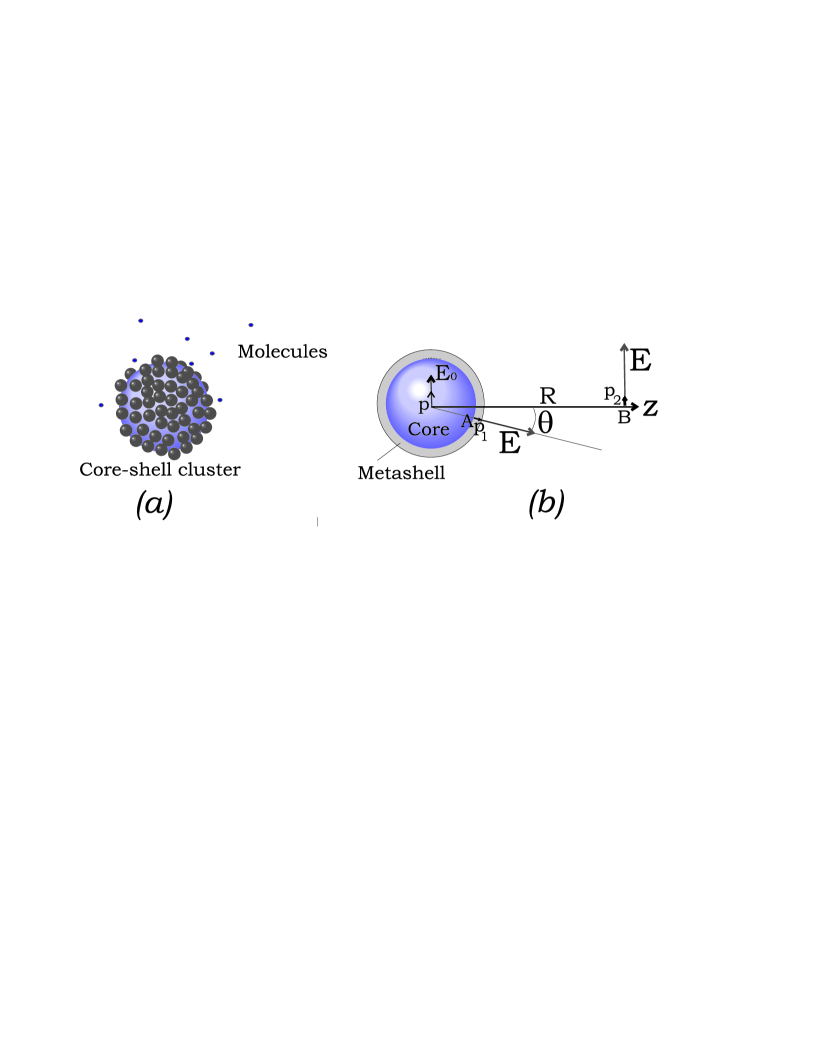
First, let us prove that the formula or still holds for ”templated particles” when . Let a molecule be located at a point inside the metashell of the spherical core. The radial component of its dipole moment at the Raman frequency is denoted in Fig. 1 (b) as . Two other components of the dipole moment are not significant for SERS in spherical ”templated particles”. This dipole creates at an arbitrary chosen observation point located in the far zone the -polarized field of complex amplitude that we can present in the form . Here ( is the known function) expresses the field produced at point in absence of the ”templated particle” by the -oriented dipole located at the same distance from as the ”templated particle” center (see Fig. 1). From reciprocity equals to the radial component of the field produced at point by an auxiliary -oriented dipole located at . Since the dipole is located very far from the ”templated particle” the incident field from which the radial field results can be approximated as the field of a plane wave with amplitude at the sphere center. By definition the local field amplitude enhancement is equal to , where as we have seen results from the plane wave refraction. Therefore the amplitude radiation enhancement due to the presence of the ”templated particle” defined as (i.e. with respect to the same molecule located at the same distance from the observation point as the ”templated particle” center) is equal to . Since this result holds for an arbitrary point , the averaged radiation and local field enhancements are also equivalent. So, the enhancement of the molecule radiation at the Raman frequency in presence of the spherical ”templated particle” is equal to the local field enhancement (with respect to an incident plane wave) in presence of the same nanoparticle in the same place. The same speculation can be done for other field components, for a cylindrical ”templated particle”, and for any other finite structure modifying the local field.
To find we have to average the intensity over the metashell volume (for spherical and cylindrical cores it is a simple numerical integration of analytical expressions). Here is the complex amplitude of the radial component of electric field when the ”templated particle” is impinged by a plane wave of unit amplitude. The intensity Raman gain is equal to .
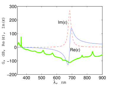
The result for (in dB) versus light wavelength for the spherical ”templated particle” with the core of radius nm is shown in Fig. 2 (a) together with the complex permittivity of the metashell. At the collective plasmon resonance of the metashell, the losses are very high and . The ”useful” WG resonance (when the field concentrates inside the shell) corresponds to the azimuthal and polar numbers of the WG mode and , respectively. It holds at nm where and . It corresponds to the averaged intensity Raman gain and to the cavity optical quality . The presence of the metashell broadens the band of the WG resonator. Cores with and nm still correspond to , as we can see from Fig. 2 (b), where ( is shown in more details for three values of the Si sphere radius. This result shows the possible tolerances in the cavity fabrication.
It had been expected that the higher-order WG resonances (when m) should have strongly increased the gain since the optical quality of cavities usually grows along with the resonance order. However, for ”templated spheres” it is not so. The next ”useful” WG resonance corresponds to nm (), however does not improve since the WG resonance shifts to lower frequencies where increases and the losses reduce the gain.
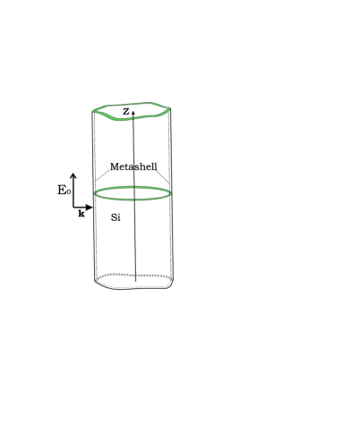
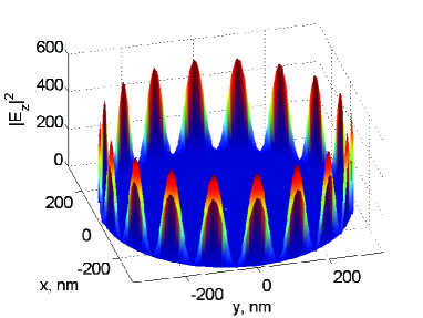
For cylinders this blue shift is absent and the gain grows versus the order of the ”useful” resonance. The case shown in Fig. 3 (a), i.e. the normal incidence of an axially polarized plane wave to an infinitely long cylinder of radius covered with the same metashell was studied. There is only one component of the electric field . In Fig. 3 (b) the distribution of the field intensity over the structure with nm at nm (the mode azimuthal number ) is shown. The localization of the field inside the metashell is clearly seen. One can see that at this frequency exceeds . However, the numerical averaging gives i.e. .
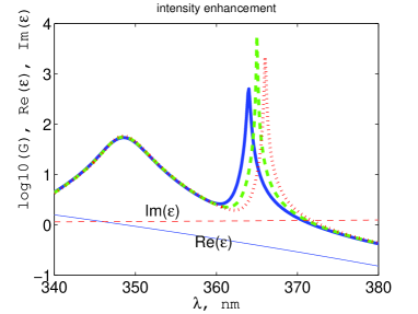
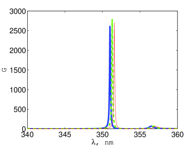
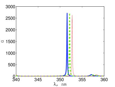
Fig. 4 (a) shows the frequency dependence of for three values of the Si cylinder radius nm corresponding to the WG modes also concentrated within the shell (the resonance order ). Then the result is much better () within the band nm, where nm. In Fig. 4 (b) the results are shown for an abstract metashell with dispersionless permittivity which is equal to . It is clear that the dispersion of the metashell permittivity has no impact but for the highest gain one has to adjust (in the region of ). The same structure at same frequency gives for .
Further increase of the cylinder radius allows us to obtain the higher gain. The result corresponding to the WG resonance of the order is . In this case the band of the WG resonance becomes as narrow as nm and the optical quality is of the order . Notice, that very high values of correspond to very narrow resonance band. Then the excitation frequency and the Raman frequency can belong to this resonance band only if the Raman shift is very small. Otherwise the approximation is not anymore valid, and the result does not hold. The ”template particles” with m have at the ”useful” WG resonance the optical quality of the order and huge Raman gain . However this gain can be applied only for molecules with very small Raman shift (less 1 cm-1 for wavenumbers). Therefore we do not consider so big ”templated particles” in more details.
To conclude: it is theoretically demonstrated that the WG resonances in core-shell ”templated particles” whose effective shell permittivity is close to zero are very promising for SERS. These structures combine useful features of SERS and cavity-enhanced Raman scattering. Exact analytical calculations were also done (for both spheres and cylinders) covered with a solid silver shell of same thickness nm. The WG resonances at which the field of WG modes is strongly localized (concentrated at the inner interface between the core and the shell) were found. These resonances demonstrated tremendous that attains even for submicron values (). This effect can be applied in prospective SRS schemes.
References
- (1) M. Fleischmann, P. J. Hendra, A. J. McQuillan, Chem. Phys. Lett. 26 (1974) 163.
- (2) M. Moskovits, Rev. Mod. Phys. 57 (1985) 783.
- (3) S. L. McCall, P. M. Platzman, P. A. Wolff, Physics Letters A 77 (1980) 381.
- (4) F. J. Adrian, Chem. Phys. Lett. 78 (1981) 45.
- (5) V. Emelyanov and N. I. Koroteev, Soviet Physics Uspekhi 24 (1981) 864.
- (6) V. N. Pustovit, T. V. Shahbazyan, J. Opt. A: Pure Appl. Opt. 8 (2006) S208.
- (7) J.P. Goudonnet, J. L. Bijeon, R. J. Wrmack, and T. L. Ferrel, Phys. Rev. B 43 (1991) 4605.
- (8) F. Garica-Vidal and J.B. Pendry, Phys. Rev. Lett. 77 (1996) 1163.
- (9) S. Nie and S. R. Emory, Science 275 (1997) 1102.
- (10) K. Kneipp, H. Kneipp, V. B. Kartala, R. Manoharan, G. Deinum, I.V. Itzkan, R. R. Dasari, and M. S. Feld, Phys. Rev. E 57 (1998) R6281.
- (11) K. Kneipp, H. Kneipp, I.V. Itzkan, R. R. Dasari, and M. S. Feld, Chem. Rev. 99 (1999) 2957.
- (12) H. Xu, E.J. Bjemeld, M. Kall, and L. Borjesson, Phys. rev. Lett. 83 (1997) 4357.
- (13) D. A. Genov, A. K. Sarychev, V. M. Shalaev, and A. Wei, Nanoletters 24 (2004) 153.
- (14) E. C. Le Ru, E. Blackie, M. Meyer, and P. G. Etchegoin, J. Phys. Chem. 111 (2007) 13794.
- (15) S. Xiao, N. A. Mortensen, A.-P. Jauho, J. Eur. Opt. Soc. 8 (2008) 08022.
- (16) H.-B. Lin, J. D. Eversole, and A. J. Campillo, Opt. Lett. 17 (1992) 828.
- (17) H.-B. Lin and A. J. Campillo, Phys. Rev. Lett. 73 (1994) 2440.
- (18) H.-B. Lin and A. J. Campillo, Opt. Commun. 133 (1997) 287.
- (19) Y. Wu, X. Yang, P.T. Leung, Optics Lett. 24 (1999) 345.
- (20) X. Yang and C. W. Wong, Optics Express 12 (2005) 4723.
- (21) A. A. Savchenkov, A. B. Matsko, M. Mohageg, and L. Maleki, Optics Lett. 32 (2007) 497.
- (22) Q. Xu, V. R. Almeida, M. Lipson, Opt. Lett. 30 (2005) 35.
- (23) F. de Leonardis and V. M. N. Passaro, New J. Phys. 9 (2007) 1.
- (24) S.-X. Qiang, J.B. Snow, H.-M. Tzeng, R.K. Chang, Science 231 (1986) 486.
- (25) K. J. Yi, H. Wang, Y. F. Lu, and Z. Y. Yang, J. Appl. Phys. 101 (2007) 063528.
- (26) C. Rockstuhl, F. Lederer, C. Etrich, T. Pertsch, T. Scharf, Phys. Rev. Lett. 99 (2007) 017401.
- (27) C. R. Simovski and S. A. Tretyakov, Phys. Rev. B 79, (2009) 045111.
- (28) L. Jiang, Z. Wu, D. Wu, Nanotechnology 18 (2007) 185603.
- (29) D. M. Kuncicky, S. D. Christensen, and O. D. Velev, Appl. Spectrosc. 59 (2005) 401.
- (30) D. M. Kuncicky, B. G. Prevo, and O. D. Velev, J. Mater. Chem. 16 (2006) 1207.
- (31) H. Jia, J. Zeng, W. Song, and B. Zhao, Thin Solid Films 496 (2006) 281.
- (32) I. Pastoriza-Santos, D. Gomez, J. Perez-Juste, L. M. Liz-Marzan, and P. Mulvaney, Phys. Chem. Chem. Phys. 6 (2004) 5056.
- (33) A. L. Aden and M. Kerker, J. Appl. Phys. 22 (1951) 1242.
- (34) M. Kerker and E. Matijevic, J. Opt. Soc. Am. 51 (1961) 506.
- (35) H. Suzuki and I.-Y. Sandy Lee, Int. J. Phys. Sci. 3 (2008) 038.
- (36) H. A. Yousif, R. E. Mattis, and K. Kozminski, Appl. Opt. 33 (1994) 4013.
- (37) H.R. Philipp and E. A. Taft, Phys. Rev. 120 (1960). 37.
- (38) P. B. Johnson and R. W. Christy, Phys. Rev. B 6 (1972) 4370.