Present address: ]Center for Nonlinear Studies, Theoretical Division, Los Alamos National Laboratory
A simple, low-cost, data-logging pendulum built from a computer mouse
Abstract
Lessons and homework problems involving a pendulum are often a big part of introductory physics classes and laboratory courses from high school to undergraduate levels. Although laboratory equipment for pendulum experiments is commercially available, it is often expensive and may not be affordable for teachers on fixed budgets, particularly in developing countries. We present a low-cost, easy-to-build rotary sensor pendulum using the existing hardware in a ball-type computer mouse. We demonstrate how this apparatus may be used to measure both the frequency and coefficient of damping of a simple physical pendulum. This easily constructed laboratory equipment makes it possible for all students to have hands-on experience with one of the most important simple physical systems.
I Introduction
Lessons and homework problems involving a pendulum are often a big part of introductory physics classes and laboratory courses. Gluck_2004 Typically experiments are limited to using photogates to measure the period of the pendulum. Commercial rotary motion sensors111Vernier order number RMS-BTD; PASCO model number PS-2120 that allow students to collect real-time motion data for a pendulum exist, but often the cost is too great to provide each student in the class with such a sensor, especially in developing countries. In contrast, a new two-button button ball-type mouse can be purchased for under US dollars and surplus used units are often available at little to no cost. Therefore we present a low-cost, easy-to-build rotary sensor pendulum using the existing hardware in a computer mouse.
There have been other attempts to use common computer peripherals as data acquisition interfaces. T. J. Bensky in 2001 described the use of a computer joystick to track the motion of a pendulum. Bensky_2001 We considered using his design when building a data-logging pendulum, but computer joysticks have changed considerably in the past years. Few, if any, models are sold that do not self-center; this is a crucial feature to Bensky’s original design. Three papers by Handler, Ochoa, and Kolp feature the use of a computer mouse in tracking motion in a Lenz’s Law experiment and in harmonic motion experiments using springs. Handler_1996 ; Ochoa_1997 ; Ochoa_1998 In each case a string was wrapped around the roller in the mouse so that a linear displacement could be measured.
In the last years since these experiments, significant changes in mouse hardware years have made it easier than ever to use a computer mouse to measure angular displacement as well. At the time that these papers were written, the rollers in the mouse featured a series of electrical contacts that would produce a signal by brushing against a wire as the mouse was moved. This has since been nearly universally replaced by an opto-mechanical mechanism that is much lower in friction. The rollers now have slotted disks, and photogates sense the motion of the disk without any physical contact required. This improved hardware is ideal for tracking the motion of a pendulum because measurement friction is low and because modern ball-type mice feature opto-mechanical mechanisms which directly measure angular displacement.
There exist computer mice that use a purely optical mechanism to detect translation, namely, a low resolution camera on the underside of the mouse. The camera repeatedly takes pictures of the surface under the mouse and interprets differences between successive frames as motion. While these mice work the same way to the user, this type of mouse has no mechanical components and is not well suited for this application. It may be possible to adapt an optical mouse for other mechanical experiments, but in this work we specifically take advantage of the hardware present in ball-type mice.
II Building the pendulum
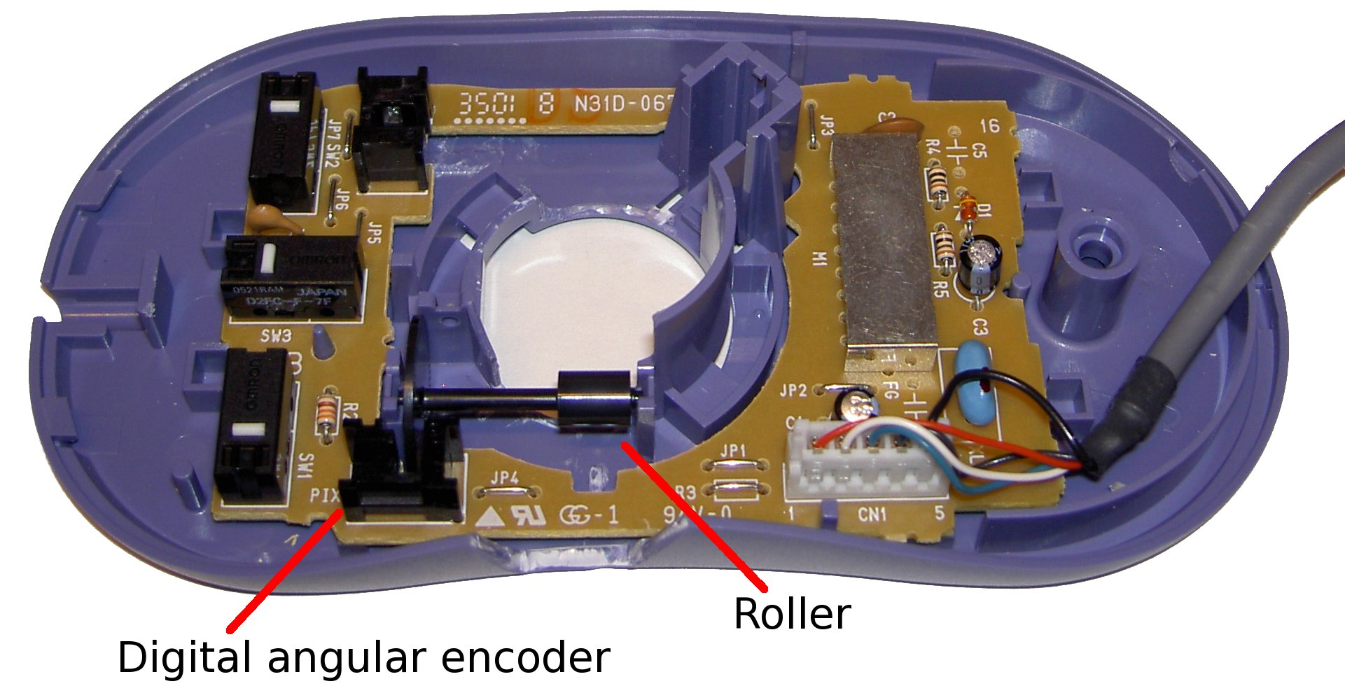
The following parts and tools are needed: a ball-type computer mouse, a wooden or plastic dowel, a small screwdriver (used to open the mouse casing), a pair of small clippers (used to cut back the mouse casing), and a small drill bit (approximately the diameter of the dowel). We remove the cover of the mouse and locate the best digital angular encoder (with roller) to use for a pendulum (see Fig. 1). We cut away enough of the cover to allow access to the encoder, then replace the cover to provide support to the assembly. In this case we allow for moderate amplitude () motion of the pendulum by cutting back the plastic near the roller. With additional hardware it is possible to mount the brackets of the roller from either side to allow for full motion of the pendulum. If the pendulum is not mounted directly to the roller but the pendulum is suspended independently and the roller is connected directly to it, measurement friction can be eliminated.
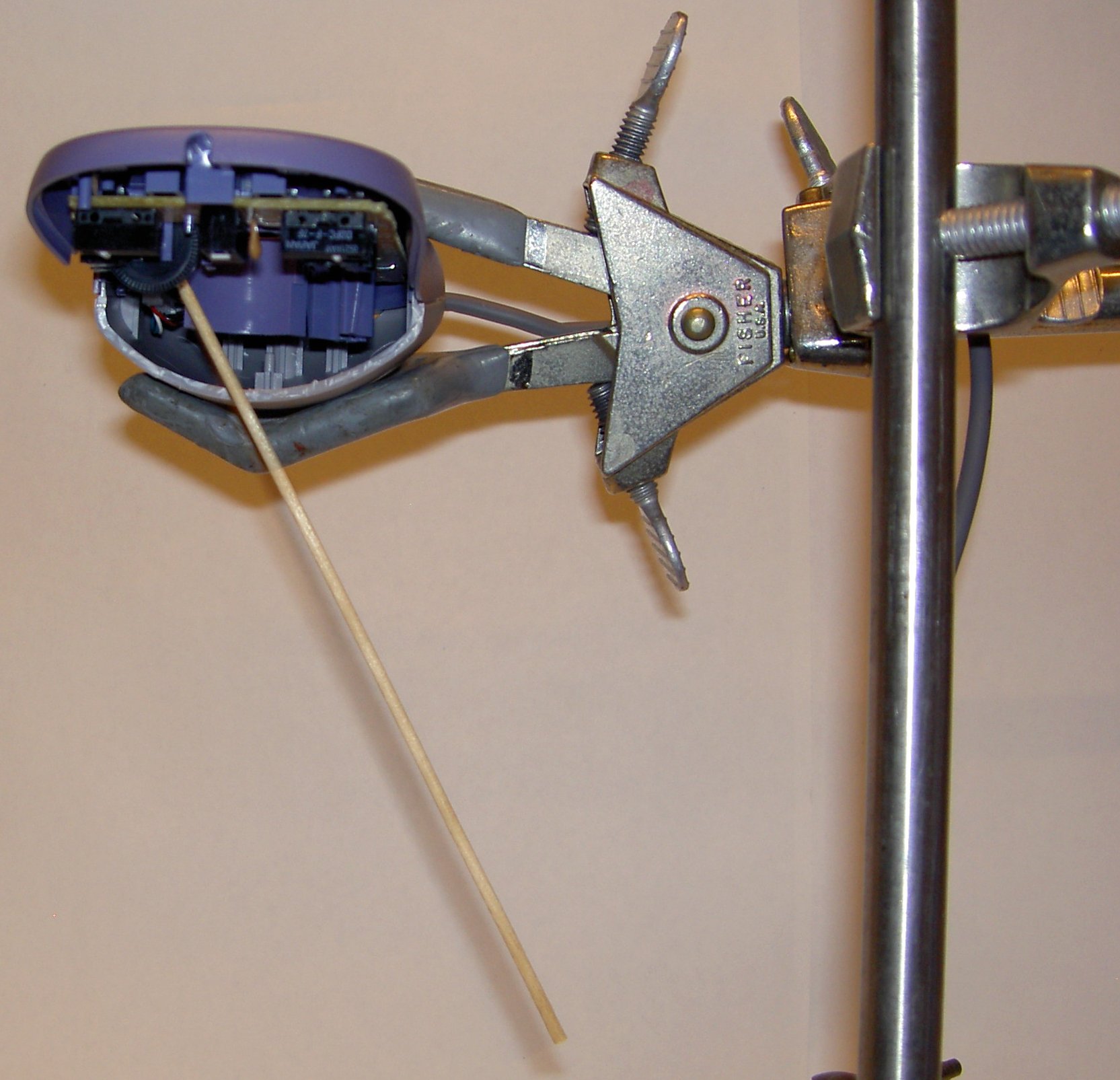
A small drill bit turned by hand will make a hole in the roller. A rod with the same diameter as the drill bit will fit into this hole and will function as the pendulum. We used a thin wooden dowel,222This pendulum has a length of cm, a diameter of mm and a mass of g. but a small plastic rod would work equally well. Since no glue is used, rods of varying lengths can be easily substituted during experiments. Fig. 2 shows the completed experimental apparatus.
III Calibration and Use
We plug the mouse into the Universal Serial Bus (USB) port of a computer.333In general, most operating systems will accept input from two mice plugged in simultaneously (via the USB port) so the pendulum need not interfere with normal operation of the computer. This was tested for Windows XP, Linux, and OS X. Mice that use other ports such as serial or PS/2 may also work in this way but nearly all computers built within the last 10 years feature multiple USB ports so this is most convenient. Be sure to turn OFF the hardware acceleration for the mouse to ensure that the displacement does not depend on the angular velocity of the roller. The resolution of the apparatus is limited by the number and spacing of the slots in the disk of the angular encoder. Therefore, it is possible to calibrate the motion of the cursor to angular displacement units. One calibration method is to determine the motion in pixels of one or more full turns of the roller. For the apparatus we built, a rotation of degrees gave a change in the position of the cursor of pixels. This results in a conversion factor of radians per pixel. A custom computer program is used to the motion of the cursor in pixels.444It is somewhat more difficult but quite possible to write a computer program that uses the data coming from the mouse itself. The resolution of this data is limited only by the resolution of the optical angular encoder within the mouse. See Endnote for a link to the source code of the computer program used to track the cursor. We find that the apparatus has a resolution of radians, which corresponds to a fractional uncertainty of out of a full turn.
The standard equation of motion of a pendulum with damping is
| (1) |
where is the moment of inertia. Here and refer to the mass and length of the rod, respectively, while is acceleration due to gravity and controls the strength of the damping term. Also, , , and are the angle measured down from the vertical, the angular velocity, and the angular acceleration, respectively. In the small angle approximation, the equation of motion reduces to
| (2) |
We can write the solution as follows:
| (3) |
where is the decay constant and is the frequency of free oscillations. Graf_2005
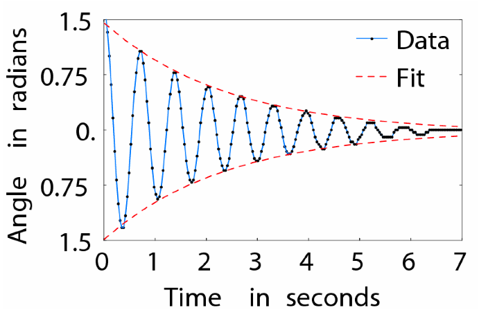
and are determined using the initial conditions. Fig. 3 shows a plot of position versus time data for the pendulum when released from rest ). The dashed line shows a fit of the turning points to an exponential decay envelope. For the pendulum, we obtain with for the fit. This simple investigation is quite easy to do using the data from this apparatus, but next to impossible using only photogates. This is a simple example of a high school or undergraduate level laboratory experiment that uses the apparatus but it is well suited to more advanced teaching applications such as exploring the driven physical pendulum or coupling between pendula.
IV Conclusion
The mouse-pendulum is a low cost solution to the need for an experimental pendulum that provides real-time angular displacement data. The small-amplitude period of the pendulum (approximately s for the apparatus we built) depends only on the length of the rod and can be easily adjusted for various experiments. This apparatus is ideal for undergraduate and even high school lab classes. Furthermore, the low cost makes it possible for teachers with very limited budgets and those in developing countries to provide each student in the class with a useful piece of lab equipment. The ease of construction allows building the pendulum to be a good classroom exercise, during which practical experimental considerations (such as how to minimize friction) may be discussed. This design is robust for serious experimental work as well.555A variation of this design was successfully used to explore synchronization between real and virtual pendula experimentally. Gintautas_2007 Source code to free data logging software to record the motion of the pendulum can be obtained online.666http://vadasg.googlepages.com/PendDataLog-src.zip LA-UR 09-00439.
References
- (1) T.J. Bensky. Measuring with a joystick pendulum. Physics Teacher, 39:88, 2001.
- (2) V. Gintautas and A. W. Hübler. Experimental evidence for mixed reality states in an interreality system. Phys. Rev. E, 75:057201, 2007.
- (3) Paul Gluck. Versatile physical pendulum. Physics Teacher, 42:226, 2004.
- (4) E. H. Graf. Computerized physical pendulum for classroom demonstrations. Physics Teacher, 43:244, 2005.
- (5) Joel T. Handler, O. Romulo Ochoa, and N. Franklin Kolp. A mouse in our laboratory. Physics Teacher, 34:488, 1996.
- (6) O. Romulo Ochoa and N. Franklin Kolp. The computer mouse as a data acquisition interface: Application to harmonic oscillators,. American Journal of Physics, 65:1115, 1997.
- (7) O. Romulo Ochoa, N. Franklin Kolp, and Joel T. Handler. Quantitative demonstration of Lenz’s law. Physics Teacher, 36:50, 1998.