Slow light of an amplitude modulated Gaussian pulse in electromagnetically induced transparency medium
Wenzhuo Tang, Bin Luo, Yu Liu, and Hong Guo∗
CREAM Group, State Key Laboratory of Advanced Optical
Communication Systems and Networks (Peking University)
and Institute of Quantum Electronics, EECS, Peking University, Beijing 100871, China
∗Corresponding author: hongguo@pku.edu.cn
Abstract
The slow light effects of an amplitude modulated Gaussian (AMG) pulse in a cesium atomic vapor are presented. In a single- type electromagnetically induced transparency (EIT) medium, more severe distortion is observed for an AMG pulse than a Gaussian one. Using Fourier spectrum analysis, we find that the distortion, as well as the loss, is dominantly caused by linear absorption than dispersion. Accordingly, a compensation method is proposed to reshape the slow light pulse based on the transmission spectrum. In addition, we find a novel way to obtain simultaneous slow and fast light.
OCIS codes: 270.1670, 270.5530.
Recently, slow light has attracted tremendous attention for its potential applications in optical communication. Group velocity of light pulse can be slowed down using various effects, such as electromagnetically induced transparency (EIT) [1, 2], double absorption line [3, 4], coherent population oscillations [5, 6], stimulated Brillouin scattering [7] and stimulated Raman scattering [8], etc. Among these effects, EIT is the most popular candidate to experimentally realize slow light for, e.g., non-modulated Gaussian pulse. However, in real communication, pulse modulation is of great importance, but has not been well studied in slow light system.
In this Letter, we demonstrate the slow light effects for amplitude modulated Gaussian (AMG) pulses in experiment, and analyze the significant distortion of the AMG pulse. Further more, a compensation method is proposed and a well-reshaped AMG pulse is obtained.
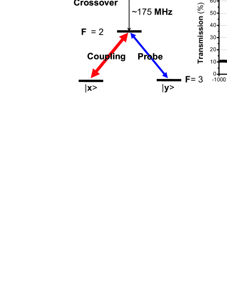
Our experimental setup is schematically illustrated in Fig. 1(a). A homemade narrowband (300 kHz) diode laser is stabilized to the transition (852 nm) of 133Cs atom: crossover. By the combination of (half-wave plate) and PBS1, the laser light is divided into two beams with perpendicular polarizations and adjustable proportion. Then, we can precisely control the optical frequency and amplitude (thus intensity) of the coupling and the probe lasers separately. The coupling laser frequency is redshifted 175 MHz by AOM2, with power 2.35 mW and beam diameter 2.0 mm. The probe pulse is generated by passing a weak (10 W) continuous-wave laser through AOM1, with the frequency redshifted 175 MHz and beam diameter 2.0 mm. In experiment, the probe field amplitude () is proportional to the amplitude of the driving radio-frequency wave to AOM1, which is directly controlled by an arbitrary waveform generator (AWG) [see Fig. 1(a)]. After that, both the coupling (vertically polarized) and the probe (horizontally polarized) light are on resonance with the transition of 133Cs atom [see Fig. 1(b)], and are combined at PBS2. Then, the overlapped lasers copropagate through the cell in order to reduce the total Doppler width of the two-photon process [9]. The beam splitter (BS) in front of the cell splits an appropriate portion of the probe to PD1 as reference, whose intensity is set to be equal to that of output when the probe is detuned far off-resonance. Thus, the background absorption is eliminated and the reference can be treated as “input”. A 10 cm-long paraffin-coated cesium vapor cell without buffer gas is used at room temperature (25 ∘C) and is placed in the magnetic shield (MS) to screen out the earth magnetic field. The exit beams are separated by PBS3, so that only the slowed probe beam reaches PD2 as the output.
In experiment, the optical intensities of the input and output pulses are recorded on a 100 MHz digital oscilloscope triggered by an AWG. Thus, the amplitudes of both the input and output (slowed) pulses can be obtained from the relation . The two probe (input) pulses with nonnegative amplitudes in time domain are chosen as
where and are the intensities of two pulses, respectively; = 700 kHz is the modulation frequency; is the FWHM of the Gaussian pulse.
The experimental results are shown in Fig. 2. The two pulses experience quite different slow light effects. For Gaussian pulse case [Fig. 2(a)], it is delayed 0.47 s, with relatively low loss and little distortion. Hence, we can compensate for the loss by directly amplifying the pulse intensity. However, for AMG pulse case [Fig. 2(b)], the output undergoes relatively high loss and significant distortion, while the delay time (0.14 s) is decreased. Thus, the direct amplification is not feasible to compensate for its loss and distortion [see the “rescaled” pulse in Fig. 2(b)].
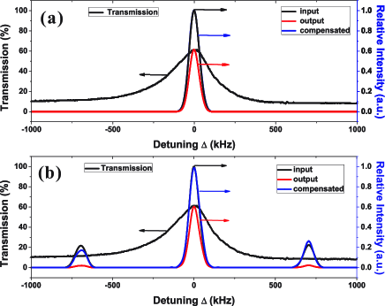
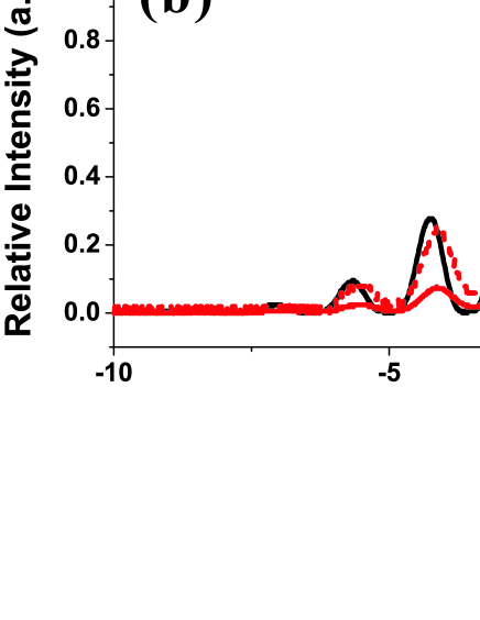
It is known that the pulse distortion is caused by both absorption and dispersion [10]. We first analyze the “absorptive distortion” using the transmission spectrum [see Fig. 1(c)]. The intensity spectrums of input, output and compensated pulse are calculated, using discrete Fourier transform (DFT) and the transmission spectrum, and are illustrated in Fig. 3. It can be seen that the intensity spectrum of the Gaussian pulse keeps unchanged with the bandwidth of 74.4 kHz; by contrast, that of the AMG pulse has not only a resonant Gaussian component, but also two non-resonant Gaussian sidebands with 700 kHz detunings. This phenomenon can be qualitatively analyzed from the Fourier intensity spectrums of two input pulses:
where and are the intensities of two spectrums, respectively; is the detuning from resonance; (determined by ) is the FWHM of the Gaussian pulse spectrum. Suppose the system is linear and , where [] is a real function related to the absorption (dispersion). Note that each spectral component has a different transmission rate that depends on its detuning. For AMG pulse, the sideband components undergo much more severe absorption than the resonant one, and so cause more significant distortion. In this way, we can explain that it is the frequency dependent absorption that causes the loss and distortion, rather than “the pulses ‘forget’ their initial temporal shapes”, as stated in [11].
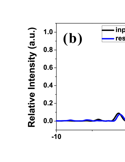
Therefore, for the linear absorption, we have , where the phase information is eliminated, and is the transmission spectrum in Fig. 1(c). A compensation method is thus proposed and applied to reshape the output pulse. As shown in Fig. 3, we obtain the compensated spectrums by simply amplifying the output spectrums according to the transmission rate as . Since the compensated and the input shown in Fig. 3 are well overlapped, this method can recover the pulse with high fidelity. To further confirm this, we transform the compensated spectrum back to time domain using inverse discrete Fourier transform (IDFT), and plot the input and the reshaped pulses (Fig. 4). The reshaped pulses of Gaussian and AMG, with different time delays, are both in good agreement with their corresponding input ones in shape and intensity. Even with the significant distortion, the output of AMG pulse has still been compensated well. Thus, only considering the frequency dependent absorption is sufficient to compensate for the distortion in a single- type system.
It should be noted that the delay time of the reshaped AMG pulse is less than that of the Gaussian one, as shown in Fig. 4. This is because the three separate spectral components of the AMG pulse experience different dispersions. By transforming each spectral component back to time domain separately, we obtain three Gaussian pulses with absolutely different time “delays”. For the resonant component, we obtain a slow light of a Gaussian pulse with the same delay time as in Fig. 4(a). On the contrary, for each sideband component, we obtain a Gaussian pulse with a little advance [fast light, see the inset of Fig. 4(b)]. As a result, the time delay for the AMG pulse is decreased. This effect, know as the simultaneous slow and fast light [12], inevitably causes distortion (“dispersive distortion”), but it is negligibly small for a single- type system [13, 14].
In conclusion, the slow light of an amplitude modulated pulse is studied, according to our knowledge, for the first time experimentally. We demonstrate that the loss and distortion of the amplitude modulated pulse are significant, which is not desirable in application. Using spectrum analysis, we analyze the loss and distortion in frequency domain in a single- type system, and point out that the distortion is dominantly caused by different absorption rate for each spectral component. Accordingly, we present a compensation method to reshape slow light pulse with high fidelity. Further, the dispersion effect is analyzed, which shows that though the “dispersive distortion” is negligible, this effect reveals a novel way, different from [12], to realize simultaneous slow and fast light. The aforementioned results can be extended to an arbitrary amplitude modulated pulse in a single- type system in EIT. These techniques of amplitude modulation and reshaping in slow light have potential applications in optical buffer and the low-distortion optical delay lines.
This work is supported by the Key Project of the National Natural Science Foundation of China (Grant No. 60837004).
References
- [1] S. E. Harris, Phys. Today 50, 36 (1997).
- [2] M. Fleischhauer, A. Imamolu, and J. P. Marangos, Rev. Mod. Phys. 77, 633 (2005).
- [3] R. M. Camacho, M. V. Pack, J. C. Howell, A. Schweinsberg, and R. W. Boyd, Phys. Rev. Lett. 98, 153601 (2007).
- [4] R. M. Camacho, C. J. Broadbent, I. Ali-Khan, and J. C. Howell, Phys. Rev. Lett. 98, 043902 (2007).
- [5] S. W. Chang, S. L. Chuang, P. C. Ku, C. J. Chang-Hasnain, P. Palinginis, and H. Wang, Phys. Rev. B 70, 235333 (2004).
- [6] P. Palinginis, F. Sedgwick, S. Crankshaw, M. Moewe, and C. J. Chang-Hasnain, Opt. Express 13, 9909 (2005).
- [7] Y. Okawachi, M. S. Bigelow, J. E. Sharping, Z. Zhu, A. Schweinsberg, D. J. Gauthier, R. W. Boyd, and A. L. Gaeta, Phys. Rev. Lett. 94, 153902 (2005).
- [8] J. E. Sharping, Y. Okawachi, and A. L. Gaeta, Opt. Express 13, 6092 (2005).
- [9] J. Gea-Banacloche, Y. Li, S. Jin, and M. Xiao, Phys. Rev. A 51, 576 (1995).
- [10] M. D. Stenner, M. A. Neifeld, Z. Zhu, A. M. C. Dawes, and D. J. Gauthier, Opt. Express 13, 9995 (2005).
- [11] G. Nikoghosyan and G. Grigoryan, Phys. Rev. A 72, 043814 (2005).
- [12] J. Zhang, G. Hernandez, and Y. Zhu, Opt. Lett. 31, 17 (2006).
- [13] R. W. Boyd, D. J. Gauthier, A. L. Gaeta, and A. E. Wilner, Phys. Rev. A 71, 023801 (2005).
- [14] R. M. Camacho, M. V. Pack, and J. C. Howell, Phys. Rev. A 73, 063812 (2006).