Reverse Doppler Effect of Sound
Abstract
We report observation of reverse Doppler effect in a double negative acoustic metamaterial. The metamaterial exhibited negative phase velocity and positive group velocity. The dispersion relation is such that the wavelength corresponding to higher frequency is longer. We observed that the frequency was down-shifted for the approaching source, and up-shifted when the source receded.
Metamaterials with negative constitutive parameters 1 ; 2 ; 3 ; 4 ; 5 brought many phenomena previously regarded impossible into reality 6 ; 8 ; 9 ; 10 . Electromagnetic waves have been demonstrated to propagate with negative phase velocity in the double negative (DNG) matematerials which have negative electric permittivity and negative magnetic permeability simultaneously. For acoustic waves, negative phase velocity is expected if density and modulus can be made simultaneously negative 11 . We combined negative density material 12 ; 13 and negative modulus material 14 ; 15 to fabricate an acoustic metamaterial that exhibits the acoustic DNG property. The negative phase velocity introduces a dispersion relation in which the wavelengths corresponding to higher frequencies become longer. By measuring the frequency shifts in the DNG metamaterial, we observed the reverse Doppler effect of sound, where the frequency was down-shifted for the approaching source and up-shifted when the source receded.
In comparison with the numerous theoretical and experimental research results on electromagnetic metamaterials, research efforts on the acoustic metamaterials are relatively few and mainly concentrated on theoretical aspects 11 ; 17 ; 18 ; 19 ; 20 ; 21 ; 22 . Only, recently, Fang et al. reported realization of negative modulus in a metamaterial consisting of Helmholtz resonators 12 . Also negative mass has been realized using a membrane by Yang et al. 14 . The authors also have investigated single negative acoustic metamaterials 13 ; 15 . Here, we present fabrication of a new acoustic DNG metamaterial by combining the two single negative metamaterials. Fig. 1a shows schematically the structure of a negative density material 13 , which has a regular array of tensioned thin membranes placed inside a tube. The metamaterial shown in Fig. 1b exhibits negative modulus due to the motion of air column in the side holes 15 . Fig. 1c shows the acoustic DNG metamaterial with the membranes and side holes alternately placed along the tube.
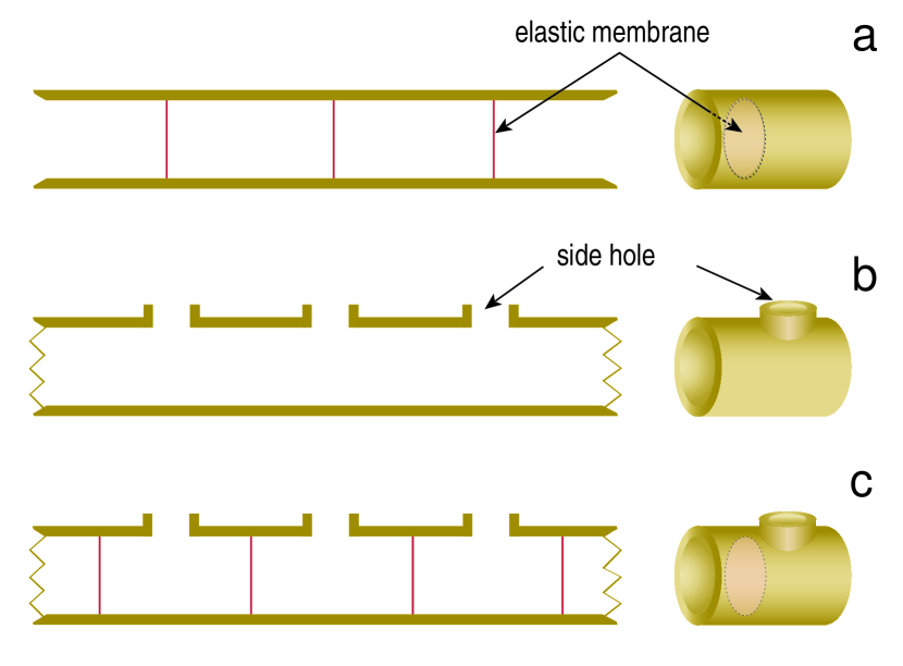
Acoustic double negativity of this structure is due to the actions of the membranes and side holes. The membrane forms a paraboloid when pushed by the fluid, and when the spacing between the membranes is much smaller than the wavelength (the long-wavelength limit), the restoring force from the tension gives the static pressure gradient where , , and are the pressure, the elastic modulus, and the displacement of the fluid, respectively. In the dynamic case, due to the force from the membranes, Newton’s equation becomes , where is the longitudinal velocity of the fluid. The volume-averaged density of the fluid (air in the present case) and the membranes, giving the inertia term in the equation, is significantly different from the dynamic effective-mass density defined below. Using the harmonic expressions , the equation can be written in a convenient form,
| (1) |
The proportionality constant of the acceleration to the pressure gradient force is defined as the effective density,
| (2) |
which becomes negative below the critical frequency .
The longitudinal wave motion in the tube is additionally affected by the motion of air moving in and out through the side holes (SH). The air column in each hole has a mass given by 23 , where is the effective length and is the cross sectional area of the hole. The mass of air moves in and out with velocity , driven by the pressure in the tube according to Newton’s law . When there are holes per unit length, we can define the SH-mass-density and the SH-cross-sectional-density as and , respectively. The SH acts as a sink that modifies the continuity equation in the tube: , where is the cross section of the tube. Using the harmonic expressions, this can be simplified to
| (3) |
The proportionality constant of the expansion to the pressure drop is defined as the effective modulus,
| (4) |
where . Thus, the system is described by the dynamic and continuity equations and , with the effective density and modulus given by equations 2 and 4. The resulting wave equation gives the phase velocity,
| (5) |
For the present system the critical frequencies, and are found to be 440 and 765 Hz respectively. That is, the effective modulus is negative below 440 Hz and the effective density is negative below 765 Hz. Thus, the system is DNG below 440 Hz and the phase velocity in equation 5 takes the negative sign. As a consequence, there are three frequency ranges: In the DNG range below 440 Hz, the acoustic waves are expected to propagate with negative phase velocities. In the negative (-NG) range from 440 to 765 Hz, the phase velocity becomes imaginary and the waves do not propagate. In the double positive (DPS) range above 765 Hz, the waves propagate with positive velocities. These predictions are experimentally verified as shown below.
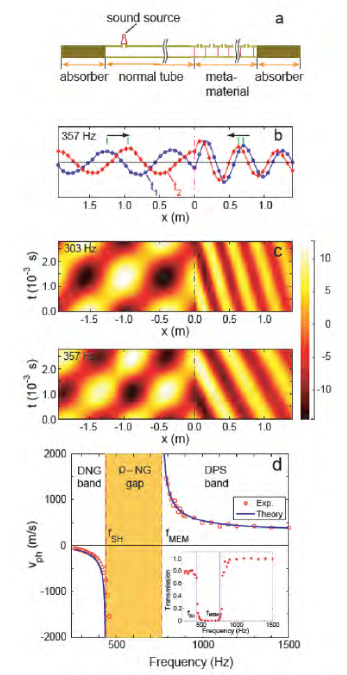
Pressure was measured as a function of time and position on both the normal tube side and the metamaterial side using the experimental setup in Fig. 2a. Typical results for the frequency of 357 Hz are shown in Fig. 2b. Two ’snapshots’ of the measured pressure distribution at times = 1.6 ms and = 2.0 ms are shown. It can be seen that on the normal tube side, the wave proceeded forward, but on the metamaterial side, the wave propagated backward, as indicated by the arrows. Clearly, the wave in the metamaterial propagated in a direction antiparallel to the energy flow. This confirms the theoretical prediction of negative phase velocity.
The overall picture of the wave motion can be seen in the characteristic diagram of in which the axes are the independent variables and (Fig. 2c). The position of the boundary is indicated by broken lines at = 0 in the diagram. For both of the exemplar frequencies (303 and 357 Hz), the slopes of the paths followed by the wavecrests in the planes were negative in the metamaterial . The phase velocities determined from the slopes were approximately -110 m/s and -200 m/s for 303 and 357 Hz, respectively. The wavelengths obtained from these values were = 0.36 m for 303 Hz and = 0.56 m for 357 Hz. The wavelength for the higher frequency was longer than that for the lower frequency. This special dispersion relation is responsible for reverse Doppler effect discussed below. In the normal tube side , the pattern of partial standing waves caused by the reflected waves from the boundary was clearly seen. The sound velocities in the normal tube obtained from the slope of the patterns for the two frequencies had the same value, 340 m/s.
Comparison between the theory and experiment are shown in Fig. 2d. Theoretically expected single negative gap is experimentally confirmed by the transmission data (inset). In the DNG and DPS pass bands, the phase velocities experimentally determined agree well with the theoretical values. Therefore, it is clear that our calculation gives an accurate description of the behavior of the phase velocity in the frequency range from 250 to 1500 Hz.
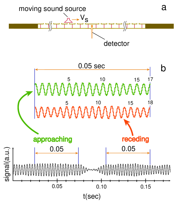
One of the most prominent features of the DNG metamaterials is the reversal of Doppler effect 1 ; 5 . However, explicit observation of reverse Doppler shift in metamaterials has not been reported, because of difficulties of phase shift measurements inside of the metamaterials. Thus, demonstration of reverse Doppler effect was so far either carried out using a circuit configuration 24 or reflecting a wave from a moving discontinuity 25 . Here we report a direct observation of the reverse acoustic Doppler effect in our DNG material. A sound source was made to move above the side holes as shown in Fig. 3a, so that the sound propagated into the tube through the holes. When the signal from the stationary detector in the tube was sent to a loudspeaker, we heard a reversed Doppler tone-shift. While the familiar Doppler tone-shift is from a high to a low pitch as the sound source passes by the listener, the shift we heard went from a low to a high pitch. The signal from the detector for a typical measurement can be seen in Fig. 3b, where we moved the source emitting 350 Hz sound at a speed of 5 m/s. The amplitude dip in the middle is due to the reversed direction of the side hole at the position of the detector (Fig. 3a). The numbers of oscillations for the approaching and receding sound sources in a time interval of 0.05 s are compared in the expanded view (Fig. 3b). The frequencies before and after the dip were determined to be 340 and 360 Hz, respectively. Obviously, the frequency was down-shifted for the approaching source, and up-shifted when the source receded. Observed Doppler shift agrees well with the measured phase velocity.
One physically meaningful question is whether sound waves in front of the moving source in our DNG material are compressed or expanded. From Fig. 2d, in the DNG band, it can be seen that the acoustic wavelength increases with frequency, i. e. high frequency corresponds to longer wavelength. Therefore, from the fact that the frequency was down-shifted, it can be inferred that the wavelength in front of a moving source became shorter. So, we conclude that even though the phase velocity is negative in the metamaterial, the waves in front of the moving source is compressed, and that in the rear is expanded.
In conclusion, we fabricated a DNG acoustic metamaterial consisting of membranes and side holes on a tube. We observed backward-wave propagation and the reverse Doppler effect in this metamaterial.
METHODS
The metamaterial shown in Fig. 1c has the inner diameter of about 32.3 mm with the length of the unit cell = 70 mm. The average density of the air loaded with the membrane in the tube was kg/m3. The modulus from the tension of the membranes was found to be N/m4. From these values a critical frequency for was calculated to be about 765 Hz. The side holes had a diameter of 10.0 mm ( = 78.5 mm2, = 821 mm2). Using the value kg, we obtained the parameters, kg/m, and m. The critical frequency for , was calculated to be about 440 Hz (where Pa).
The experimental setup in Fig. 2a consists of a normal tube on the left and a 2 m long DNG metamaterial on the right. The absorbers at both ends completely absorb the acoustic energy, preventing any reflection and, thus, the system behaves as if it extends to infinity. This eliminates concerns about the effect of the finite number of cells used in the experiment, as well as the interference effect from the reflected waves. The sound source injects acoustic energy into the tube through a small hole, generating incident waves propagating to the right. At the boundary, a portion of the incident energy is reflected and the rest is transmitted into the metamaterial region. On the metamaterial side, the transmitted acoustic energy flows steadily to the right until it hits the absorber. Waves propagating in this one-dimensional setup are monitored by measuring pressures using miniature microphone.
Sound source in Fig. 2a was a miniature speaker (RP-HV102, Panasonic Inc., 15 mm in diameter). Sound source in Fig. 3a, with a diameter of 50 mm, was made to move 10 mm above the metamaterial tube with an adjustable speed. The detectors were high sensitivity miniature condenser-type microphones (MS-9600, Neosonic Inc., 7 mm in diameter) with a thin connecting lead. The speakers were driven by an arbitrary function generator (33220A, Agilent).
References
- (1) Veselago, V. G. Electrodynamics and substances with simultaneously negative values of and . Sov. Phys. Uspekhi 10, 509-514 (1968).
- (2) Pendry, J. B., Holden, A. J., Stewart, W. J. & Youngs, I. Extremely low frequency plasmons in metallic mesostructures. Phys. Rev. Lett. 76, 4773-4776 (1996).
- (3) Pendry, J. B., Holden, A. J., Robin, D. J. & Stewart, W. J. Magnetism from conductors and enhanced nonlinear phenomena. IEEE Trans. Micr. Theory Tech. 47, 2075-2084 (1999).
- (4) Smith, D. R., Padilla, W. J., Vier, D. C., Nemat-Nasser, S. C. & Schultz, S. Composite medium with simultaneously negative permeability and permittivity. Phys. Rev. Lett. 84, 4184-4187 (2000).
- (5) Caloz, C. & Itoh, T. Electromagnetic metamaterials - Transmission line theory and microwave applications. (Wiley, New York 2006) and references therein.
- (6) Pendry, J. B. Negative refraction makes a perfect lens. Phys. Rev. Lett. 85, 3966-3969 (2000).
- (7) Zhu, J. & Eleftheriades, G. V. Experimental verification of overcoming the diffraction limit with a volumetric Veselago-Pendry transmission-line lens. Phys. Rev. Lett. 101, 013902 (2008).
- (8) Schurig, D. et al. Metamaterial electromagnetic cloak at microwave frequencies. Science 314, 977-980 (2006).
- (9) Chen, H., Wu, B.-I., Zhang, B & Kong, J. A. Electromagnetic wave interactions with a metamaterial cloak. Phys. Rev. Lett. 99, 063903 (2007).
- (10) Li, J. & Chan, C. T. Double-negative acoustic material. Phys. Rev. E70, 055602(R) (2004).
- (11) Yang, Z., Mei, J., Yang, M, Chan, N. H. & Sheng, P. Membrane-type acoustic metamaterial with negative dynamic mass. Phys. Rev. Lett. 101, 204301 (2008).
- (12) Lee, S. H., Park, C. M., Seo, Y. M., Wang, Z. G. & Kim, C. K. Negative effective density in an acoustic metamaterial. Submitted for publication to New J. Phys. (arXiv: 0812.2954v3) (2008).
- (13) Fang, N. et al. Ultrasonic metamaterials with negative modulus. Nature Mater. 5, 452-456 (2006).
- (14) Lee, S. H., Park, C. M., Seo, Y. M., Wang, Z. G. & Kim, C. K. Acoustic metamaterial with negative modulus. Submitted for publication to J. Phys.: Condens. Matter (arXiv: 0812.2952v2) (2008).
- (15) Cheng, Y., Xu, J. Y., & Liu, X. J. One-dimensional structured ultrasonic metamaterials with simultaneously negative dynamic density and modulus. Phys. Rev. B77, 045134 (2008).
- (16) Hu, X. Ho, K.-M., Chan, C. T. & Zi, J. Homogenization of acoustic metamaterials of Helmholtz resonators in fluid. Phys. Rev. B77, 172301 (2008).
- (17) Ambati, M., Fang, N., Sun, C. & Zhang, X. Surface resonant states and superlensing in acoustic metamaterials. Phys. Rev. E75, 195447 (2007).
- (18) Guenneau, S., Movchan, A., Petúrsson, G. & Ramakrishna, S. A. Acoustic metamaterials for sound focusing and confinement. New J. Phys. 9, 399 (2007).
- (19) Cummer, S. A. & Schurig, D. One path to acoustic cloaking. New J. Phys. 9, 45 (2007).
- (20) Chen, H., & Chan, C. T. Acoustic cloaking in three dimensions using acoustic metamaterials. Appl. Phys. Lett. 91, 183518 (2007).
- (21) Blackstock, D. T. Fundamentals of physical acoustics. (Wiley, New York 2000).
- (22) Kevin, M. K., Leong, H., Lai, A. & Itoh, T. Demonstration of reverse Doppler effect using a left-handed transmission line. Micr. Optic.Tech. Lett. 48, 545-547 (2006).
- (23) Seddon, N. & Bearpark, T. Observation of the inverse Doppler effect. Science 302, 1537-1540 (2003).
Acknowledgements
The research was partially supported by The Korea Science and Engineering Foundation (KOSEF R01-2006-000-10083-0).
Competing financial interests
The authors declare that they have no competing financial interests.