Capacity Bounds of Half-Duplex Gaussian Cooperative Interference Channel
Abstract
In this paper, we investigate the half-duplex cooperative communication scheme of a two user Gaussian interference channel. We develop achievable region and outer bound for the case when the system allow either transmitter or receiver cooperation. We show that by using our transmitter cooperation scheme, there is significant capacity improvement compare to the previous results [9, 10], especially when the cooperation link is strong. Further, if the cooperation channel gain is infinity, both our transmitter and receiver cooperation rates achieve their respective outer bound. It is also shown that transmitter cooperation provides larger achievable region than receiver cooperation under the same channel and power conditions.
Index Terms:
Multi-user capacity, cooperative communications, relay channel, dirty paper coding, Wyner-Ziv compress-and-forward.I INTRODUCTION
In wireless ad hoc networks, spatially dispersed radio terminals can exploit cooperative diversity [1, 2] by relaying signals for each other. With cooperation, different clusters of terminals can act like transmit/receive antenna arrays and achieve increased spatial diversity and throughput by joint encoding and/or decoding.
The capacity of the two-user Gaussian interference channel (IC) is an open problem for many years and is completely known only in some special cases (e.g., in the strong interference case [8]). The capacity region has been studied under various cooperative strategies. Most of these schemes assume that nodes operate in full-duplex mode. A coding scheme for transmitter cooperation using decode-and-forward (DF) for relaying and dirty paper coding (DPC) for codeword generation is proposed in[3]. Compress-and-forward (CF) and DF relaying strategies for receiver cooperation are proposed in [4] and generalized to both transmitter and receiver cooperation in [5]. A comparison of different coding schemes for transmitter cooperation in terms of the relative geometry of transmit and receive clusters is given in [6]. The sum rate capacity with transmitter only, receiver only and both transmitter and receiver cooperation is studied in [7]. By using DF and DPC at the cooperative transmitters and Wyner-Ziv CF at the receivers and assuming equal power gain for all channels, the proposed scheme in [7] is shown to have significant capacity gain over strong IC [8]. While full-duplex cooperative IC has been significantly studied, only limited results are known in the half-duplex scenario. Cooperative diversity with transmitter cooperation for fading channels is considered in [2]. A 2-phase transmitter cooperation scheme using DF and the so called recycling DPC (RDPC) is introduced in [9]: Similar schemes are also proposed in [10], where the transmitters have additional flexibility in choosing the order of DPC.
In this paper, we compute bounds on the capacity of two user Gaussian IC in two different scenarios: i) transmitter cooperation (TC) and ii) receiver cooperation (RC). Specifically, we allow all nodes to operate in half-duplex mode only, which requires simpler and cheaper hardware.
In TC, the two transmit nodes serve as relays to each other. We assume that the channel gain between the two transmitters is much higher than the others. In this case, it is well known that DF strategy is superior [11, 12]. Thus, in this paper we derive the achievable region with TC using only the DF strategy. We show that the achievable region of the proposed TC strategy is strictly larger than the results in [9, 10], especially when the cooperation link is strong. In case when the cooperation channel gain is infinity, the proposed achievable region achieves the system upper bound. In contrast, for the schemes in [9, 10], there is a large performance gap between the lower and upper bounds.
In RC, the two receive nodes serve as relays to each other. In this case, we assume that the relay to destination channel is strong for RC, and CF [11] is preferable at the relays. Thus, to derive the achievable region with RC, we only consider the CF strategy. The proposed scheme achieves the corresponding MIMO multiple access channel (MAC) capacity [13] when the cooperation channel gain is infinity. To the best of our knowledge, the achievable rate with RC has not been studied under the half-duplex assumption. We also show that under identical channel conditions and equal transmit power constraints on all nodes, TC achieves larger rates than RC.
II SYSTEM MODEL
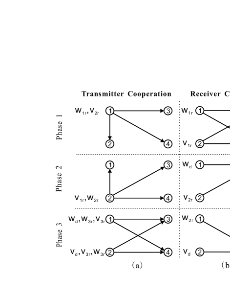
Consider a two-transmitter two-receiver network shown in Fig. 1, where node is the intended receiver of node and node is the intended receiver of node . The independent messages transmitted by node are encoded into complex symbols , under the power constraint . If the messages transmitted by node and has a total alphabet of and respectively, their respective rates are then and bits/transmission. The channel gain from node to node and , is represented by a complex constant . It is assumed that all nodes have perfect knowledge of the channel gain and all the phase offsets can be perfectly synchronized. Let denote the i.i.d. complex circularly symmetric Gaussian noise process at node , with the element . We assume that the communication is in a half-duplex fashion, i.e., each of the nodes can be either in the transmit mode or the receive mode. For TC, only the two transmit nodes (node 1 and 2) can cooperate with each other while for RC, only the two receive nodes (node 3 and 4) can cooperate with each other. It is also assumed that the cooperation nodes are close together, i.e., and are large compared to the other ’s. Further, we define the following non-negative parameters satisfying , , , , , and . Also define , , and . Let .
III TRANSMITTER COOPERATION
III-A Achievable Rates
Theorem 1
Proof: We construct a 3-phase transmission strategy as shown in Fig. 1-(a), to show the achievability. Let ’s and ’s be the messages intended to node 3 and 4 respectively. The specific message sent in each phase is detailed in Fig. 1-(a). In phase 1 and 2, the two source nodes transmit messages and to each other, and and to the receive nodes by broadcasting their signals using DPC. In phase 3, after the sources exchanged their information, the system is equivalent to a two user 2-transmit-1-receive antenna MIMO BC. The source nodes can then jointly broadcast and to the receivers using DPC [14]. Further, the two source nodes can also send and in phase 3, respectively. Due to the limited space, we only outline the results at each phase.
Transmission Scheme: The transmission is divided into 3 phases as shown in Fig. 1-(a), with time portion and . In Phase 1, node is in transmit mode and all other nodes are in receive mode. The received signal at node and 4. In Phase 2, node is in the transmit mode and all the other nodes are in receive mode. In Phase 3, nodes and are in transmit mode and nodes and are in the receive mode. The received signal in phases 2 and 3 can easily be expressed similar to phase 1.
Outline of Achievability:
1) Phase 1: If , generate codeword with length and power . Given , use DPC to generate with length and power . Otherwise, do DPC with the reverse order. Since is known to node 2, it can subtract and decode if the rate of satisfies [9]
| (3) |
Node 3 can decode if the rate of satisfies
2) Phase 2: If , generate codeword with length and power . Given , use DPC to generate with length and power . Otherwise, do DPC in the reverse order. Node 1 can decode if the rate of satisfies [9]
| (4) |
and node 3 can decode if the rate of satisfies
3) Phase 3: After phase 1 and 2, and have been exchanged between the sources. Node 1 and 2 can then sent messages jointly using the coding scheme of a two user 2-transmit-1-receive antenna MIMO BC [14]. The problem now is to find the optimal covariance matrices of the two transmit signals for both receive node 3 and 4. In [15], a simple method of generating MIMO BC covariance matrices is proposed by transforming the covariance matrices from its dual, MIMO MAC. We use this method to find the covariance matrices and in our coding scheme.
If , generate codeword with length and power at node 2. Generate codeword and with length at node 1 and 2 respectively with covariance matrix , where can be found by using the results given in [15]. Let , then . Let , then . Given and , use DPC to generate codeword with length and power at node 1. Generate codeword and with length at node 1 and 2 respectively with covariance matrix . If , do DPC with the reverse order. Note that in this case, the covariance matrix becomes , where and , where 111It is easy to show that if we let and , the achievable rates of our scheme reduces to the rates given by parallel coding DPC in [10] (or RDPC in [9], if we further restrict the condition to and ). Note that using the above covariance matrices pairs is equivalent to the case assuming random phase shifts for different channels, i.e., the received signal from different transmitters can not be synchronized.. Node 3 first decodes , it can do so if the rate of satisfies
Node 3 then decodes , if the rate of satisfies
| (5) |
After decoding and , node 3 can finally decode if the rate of satisfies
| (6) |
where
Similarly, node 4 first decodes , if the rate of satisfies
Node 4 can then decode if the rate of satisfies
| (7) |
After decoding and , node 4 can decode if the rate of satisfies222Note that for the transmission order given in Fig. 1-(a), is encoded and transmitted in phase 2, the receiver can decode it only after and been decoded at phase 1 and 3 of the next transmission block.
| (8) |
where
III-B Outer Bound
For TC, when , the system becomes a two user 2-transmit-1-receive antenna MIMO BC. The capacity region of this MIMO BC [14] is an outer bound on achievable rate. Further, when one user is silent, the achievable rate for the active user is bounded by the single user half-duplex relay channel max-flow-min-cut bound [12]. Hence, with TC, the set of achievable rate pairs satisfies
| (9) | ||||
| (10) |
where and is the union of all rates with any power allocations and that satisfies the total power constraint , and
where and ,
IV RECEIVER COOPERATION
IV-A Achievable Rates
Theorem 2
Proof: The 3-phase RC scheme is shown in Fig. 1-(b). In phase 1, the signals from node 1 and 2 are received at node 3 and 4. Rather than decoding the signals, the two receive nodes exchange information in phase 2 and 3 by sending each other a compressed version of what they received. The receive nodes then perform decoding by using the aggregation of the compressed signal and the signal directly received in phase 1. Let ’s and ’s be the messages intended to node 3 and 4 respectively. The specific message sent in each phase is detailed in Fig. 1-(b). We outline the coding scheme as follows.
Transmission Scheme: In Phase 1, nodes and are in receive mode and nodes and are in transmit mode. Again, since the expressions of the received signals can be easily shown, we omit them due to limited space. In Phase 2, node is in receive mode and all the other nodes are in transmit mode. In Phase 3, node is in receive mode and all the other nodes are in transmit mode.
Outline of Achievability:
Phase 1: At nodes 1 and 2, generate length codewords and with powers and respectively.
Phase 2: At node 1 and 2, generate length codewords and with powers and respectively. At node , generate length codewords and 333Note that is the message decoded at phase 3 of the previous block. It is re-encoded as and relayed to the intended receiver. with power and respectively. Node 3 first decode , if the rate of satisfies
| (13) |
Node 3 can then decode , if the rate of satisfies
| (14) |
and decode and , if their respective rates satisfy
| (15) | ||||
| (16) |
Phase 3: At nodes 1 and 2, generate length codewords and with powers and respectively. At node 3, generate length codewords and with powers and respectively. Node 4 can decode if
| (17) |
Combining (15) and (17), node 4 can decode if
| (18) |
Node 4 can then decodes , if the rate of satisfies
| (19) |
After decoding and , node 4 decodes if
| (20) |
Combining (20) and (13), node 3 can decode if
| (21) |
Finally, node 4 can decode if the rate of satisfies
| (22) |
We now consider the decoding of and . By decoding and , a compressed version of the signals received in phase 1 have been exchanged between the receivers. Let and be the compression noise of the received signal at node 3 and 4 respectively. Using similar derivations as in [7], and are given by
| (23) | ||||
| (24) |
where is a diagonal matrix.
As discussed in [7], since each receiver has a noisy version of the received signal of the other receiver, the network is equivalent to an IC with two receive antennas at each receiver. After normalizing the noise power to 1 for all receive “antennas”, the equivalent channel gains between the transmit and receive node pairs are given as , , and , where . Let , , and
The capacity region of a 1-transmit-2-receive antennas IC is not known except for the strong interference case [16] ( and ). In this case, the messages and can be decoded if their respective rate and satisfies [16]
| (25) | ||||
| (26) | ||||
| (27) |
When , node 4 can eliminate the interference by completely decoding the message transmitted from node 1 and node 3 can decode by treating its interference as noise. Thus, the achievable rates of and are respectively
| (28) | ||||
| (29) |
Similarly, when , the achievable rates of and are respectively given by
| (30) | ||||
| (31) |
IV-B Outer Bound
V NUMERICAL EXAMPLES
We compare our achievable region to some known results through numerical examples. We focus on the symmetric channel case (similar results can be shown for the asymmetric case). We set the direct channel gains as , the cross channel gains as and the average power constraints .
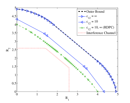
Fig. 2 compares the achievable region from our TC scheme with RDPC [9, 10]. It is shown that the achievable region using our TC scheme is significantly larger than using RDPC. Further, the capacity gain of our TC scheme increases with the cooperation channel gain: As we increase the cooperation channel gain from to , the achievable region meets the outer bound. On the other hand, the achievable region of RDPC does not increase as long as the cooperation channel is not a capacity threshold (see equations (8) and (9) in [9]). The achievable regions are also compared to the capacity of a standard strong IC (without node cooperation). It is clear that by allowing node cooperation, the achievable region increases significantly.

Fig. 3 shows the achievable regions for both TC and RC. Similar to TC, the achievable region of RC also increases with cooperation channel gain. When , the achievable region of RC overlaps with the outer bound. The RC achievable region is also compared with TC. When , the achievable region of TC is strictly larger than RC. When , both schemes meet their respective outer bound. However, due to the single user half-duplex relay channel capacity constraints (see (9)), RC achieves less single user rates under the assumed channel conditions.
Bridging the gap between the outer bound and the achievable region for finite cooperative channel gains should be considered in future work.
References
- [1] A. Sendonaris et al., “User cooperation diversity–Part I and II,” IEEE Trans. Comm., vol. 51, pp. 1927–1948, Nov. 2003.
- [2] J. Laneman et al., “Cooperative diversity in wireless networks: Efficient protocols and outage behavior,” IEEE Trans. Inf. Thy., vol. 50, pp. 3062–3080, Dec. 2004.
- [3] A. Host-Madsen, “A new achievable rate for cooperative diversity based on generalized writing on dirty paper,” in Proc. of IEEE ISIT, p. 317, June 2003.
- [4] A. Host-Madsen, “On the achievable rate for receiver cooperation in ad-hoc networks,” in Proc. of IEEE ISIT, p. 272, June 2004.
- [5] A. Host-Madsen and A. Nosratinia, “The multiplexing gain of wireless networks,” in Proc. IEEE ISIT, pp. 2065–2069, Sept. 2005.
- [6] C. Ng and A. Goldsmith, “Transmitter cooperation in ad-hoc wireless networks: Does dirty-paper coding beat relaying?,” in Proc. IEEE ISIT, pp. 2065–2069, Sept. 2005.
- [7] C. Ng et al., “Capacity gain from two-transmitter and two-receiver cooperation,” IEEE Trans. Inf. Thy., vol. 53, pp. 3822–3827, Oct. 2007.
- [8] H. Sato, “The capacity of the gaussian interference channel under strong interference,” IEEE Trans. Inf. Thy., vol. 27, pp. 786–788, Nov. 1981.
- [9] K. Shum and C. Sung, “Transmitter cooperation by recycling dirty paper,” in Proc. IEEE ISIT, pp. 777–781, July 2008.
- [10] N. Fawaz et al., “When network coding and dirty paper coding meet in a cooperative ad hoc network,” IEEE Trans. Wireless Commun., vol. 7, pp. 1862–1867, May 2008.
- [11] G. Kramer et al., “Cooperative strategies and capacity theorems for relay networks,” IEEE Trans. Inf. Thy., vol. 51, pp. 3037–3063, Sept. 2005.
- [12] A. Host-Madsen and J. Zhang, “Capacity bounds and power allocation for wireless relay channels,” IEEE Trans. Inf. Thy., vol. 51, pp. 2020–2040, June 2005.
- [13] E. Telatar, “Capacity of multi-antenna Gaussian channels,” European Trans. Telecomm., vol. 10, pp. 585–596, Nov. 1999.
- [14] H. Weingarten et al., “The capacity region of the Gaussian multiple-input multiple-output broadcast channel,” IEEE Trans. Inf. Thy., vol. 52, pp. 3936–3964, Sept. 2006.
- [15] S. Vishwanath et al., “Duality, achievable rates, and sum-rate capacity of Gaussian MIMO broadcast channel,” IEEE Trans. Inf. Thy., vol. 49, pp. 2658–2668, Oct. 2003.
- [16] S. Vishwanath et al., “On the capacity of vector gaussian interference channels,” IEEE Inf. Thy. Workshop, pp. 365–369, Oct. 2004.