As published in Supercond. Sci. Technol. 22, 025009 (2009)
High-temperature superconducting fault current microlimiters
J A Lorenzo Fernández1,2, M R Osorio1, J A Veira1 and F Vidal1111Corresponding author (felix.vidal@usc.es; fax +34 981531682; tel. +34 981563100 ext.14031).
1Laboratorio de Baixas Temperaturas e
Superconductividade
Departamento de Física da Materia
Condensada,
Universidade de Santiago de Compostela,
E-15782, Spain
2Departamento de Física de la Materia Condensada
Facultad de Ciencia y Tecnología,
Universidad del País Vasco,
Bilbao E48080, Spain
Abstract. High-temperature superconducting microbridges implemented with YBa2Cu3O7-δ thin-films are shown to be possible fault current limiters for microelectronic devices with some elements working at temperatures below the superconducting critical temperature and, simultaneously, under very low power conditions (below W). This is the case in the important applications of superconductors as SQUID based electronics, and technologies for communication or infrared detectors. In this paper it is shown that the good thermal behavior of these microlimiters allows working in a regime where even relatively small faults induce their transition to highly dissipative states, dramatically increasing their limitation efficiency. The conditions for optimal refrigeration and operation of these microlimiters are also proposed.
1 Introduction
Fault current limiters (FCL) are one of the most promising applications of high critical temperature () superconductors [1, 2, 3]. In their resistive version, these devices are directly based on the transition to a dissipative state induced by current densities above , the critical current density. Up to now research on FCL based on high- superconductors has focused high power applications, such as electric power distribution networks [3]. No attention has been paid to their possible use in microelectronic devices with some elements working at temperatures below (the superconducting critical temperature) and, simultaneously, under very low power conditions (below W). This is the case in the important applications of superconductors as SQUID based electronics and technologies for communication or infrared detectors [1]. Conventional limiters for electronic applications are usually intended to work at room temperature, or even above, but they are not easily available for cryogenic temperatures, as for instance below K, the boiling temperature of liquid nitrogen under normal pressure. At these low temperatures the performance of semiconductor devices is greatly affected. Moreover, some commercial and widely used low power current limiters, such as those based on polymeric materials, need a long time, of the order of seconds, to react to a fault, this time being longer the lower the fault current [4]. In the above applications the power involved in the faults will remain well below 1 W, which may be easily dissipated in cuprate thin-film bridges having widths in the micrometric range [5]. In addition, it was recently shown that the thermal behaviour of these microbridges may be improved by reducing their relative width [6].
The first aim of this paper is to show experimentally that, when used as fault current limiters, it is possible to refrigerate very efficiently the superconducting microbridges and then to work at stationary conditions well above , even before the fault. This is a crucial advantage compared with the behavior of the much bigger superconducting thin films needed in high power applications [1, 3], because it allows one to appreciably reduce the relative excess voltage needed to trigger the FCL and, simultaneously, dramatically increases their limitation efficiency. The conditions for good refrigeration and for optimal operation are also analyzed, the latter on the basis of the propagating hotspot approach [7, 8, 9].
2 Experimental details and thermal requirements
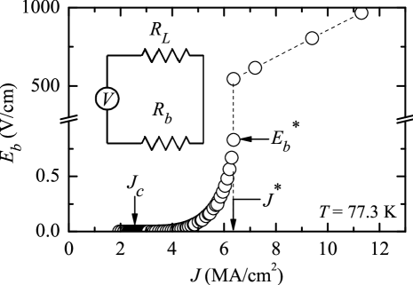
In our experiments, we have used high-quality c-axis oriented YBa2Cu3O7-δ (YBCO) thin film of thickness 120-300 nm grown on SrTiO3 or sapphire substrates (square shaped 5 mm wide and 0.5-1 mm thick) by using high-pressure on-axis DC sputtering (for those films grown in our laboratory), or by using pulsed laser deposition (Theva GmbH, Germany). Details about the growth parameters, characterization of the films and preparation of the microbridges have been described elsewhere [5]. A typical electric field versus current density () curve, corresponding to one of the microbridges (denoted BS7) used in our experiments, is shown in figure 1. This microbridge, with length, width and thickness 385 m, 28 m and 300 nm, respectively, and with K, has been grown on a sapphire substrate. The two characteristic current densities are indicated in this figure: the critical, , at which dissipation first appears, and the so-called supercritical, , at which the microbridge is triggered into highly dissipative states. This behavior makes these microbridges good candidates as FCL, but their usefulness also crucially depends on their thermal stability before and during the fault and their thermal reversibility once the fault disappears.
Some estimations may illustrate how the practical method of fulfilling the thermal requirements indicated above depends very much on the relative dimensions of the superconducting bridges and their substrates. Note first that at temperatures between 80 K and the heat transfer coefficient between the YBCO bridges and their substrates is of the order of W/cm2K, whereas towards the N2 liquid or between the substrate and its copper holder () they are typically times less [10, 11]. These values already indicate that the thermal exchanges of the bridge will mainly be through its substrate. In addition, if the corresponding Biot number [12], , is much less than one and, simultaneously, the thermal diffusion length, , is larger than the corresponding thickness, e, the increase in the microbridge temperature relative to that of the bath, , may be crudely approximated as,
| (1) |
where is the microbridge thickness and and are the surface areas of the superconductor bridge and, respectively, its substrate. As , will directly depend on , the condition of “thermal smallness” being,
| (2) |
under which approaches its “intrinsic” value, which is the temperature increase just associated with the effective thermal resistance of the bridge-substrate interface.
For the BS7 microbridge and under faults with characteristic times above 10 ms (of the order of commercial ac current periods), the conditions, and fully apply. In addition, as whereas , this microbridge is “thermally small”. One may use equation (1) to estimate when the microbridge is in stationary conditions under currents just below . From figure 1, the power density involved is around W/cm3 which leads, by also using the appropriate parameter values222The substrate thermal conductivities () and heat capacities () are of the order of 10 W/cm K and 0.6 J/cm3 K for sapphire, and 0.2 W/cm K and 1 J/cm3 K for SrTiO3, whereas for YBCO bridges W/cm K and J/cm3 K. See, e. g., Refs. [10, 11, 12]., to K. Even for faults involving powers ten times higher than those considered above, will remain below 1 K. One may also use equation (1) to roughly estimate that if the superconducting bridge had times larger, as it is the case of those currently proposed for high power applications [1, 3], would take values at least two orders of magnitude higher. To confirm these values at a quantitative level, has been calculated by using a finite element method similar to the one described in [13]. Under the same conditions as above, for the BS7 microbridge we found again K.
In the case of SrTiO3 substrates, which have relatively poor thermal conductivities, the condition no longer applies. Therefore, a term proportional to (i.e. to the inverse of the thermal conductivity of the substrate) must be added in equation 1. For microbridges under the same conditions as before, this leads to K, a value that is confirmed by using the finite element method mentioned above. Let us stress, finally, that for a bridge on sapphire but having a surface relative to that of its substrate times larger, the finite element method yields K.
3 Experimental results: optimal operation
To probe a microlimiter with low thermal dimensions, we have implemented the electrical circuit schematized in the inset of figure 1, with the microbridge BS7 as connected in series to the variable load resistance , this last one representing the impedance of the circuit to be protected. The measurements were made in a cryostat with the sample submerged in a forced flow of helium gas. The temperature of the copper holder of the microlimiter was measured with a platinum thermometer and regulated with an electronic system which ensures a temperature stabilization better than 0.05 K. Two examples of the curves obtained in this circuit (with , this value taking already into account the resistance of the circuit electrical wires, of the order of ) by using the electronic system described elsewhere [5, 6] are shown in figure 2. In these curves the voltage was imposed and acquired during pulses of 1 s, a time much longer than the one needed by the microlimiter to reach the stationary state. The bath temperatures were 81.9 K (circles) and 85.0 K (triangles). As below the flux-flow resistance of the microbridge remains much lower than , both curves are almost linear up to . Together with the low heating estimated above, this quasi-ohmic behavior is crucial to allow the microlimiter to work just below under stationary conditions and without disturbing the circuit to be protected.
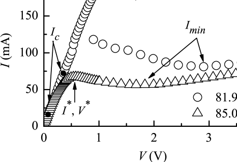
The results presented in figure 2 also illustrate two other central aspects of the microbridges when working as FCL. Note first that, once the source voltage overcomes , the current in the circuit varies quite slowly even up to voltage faults as important as four times , the current taking a minimum value, , at some (temperature-dependent) voltage. Moreover, the sharp drop at of the current is also temperature dependent, being almost absent in the curve at 85.0 K. Both aspects are related and may be explained in terms of the approaches based on the propagation of self-heating hotspots [7, 8, 9]: Above part of the microbridge becomes normal and then, as the total voltage of the circuit is fixed, the increase in resistance gives rise to a decrease in current up to the minimum current, , capable of sustaining the normal zone. If the fault voltage increases, the length of the hotspot will grow accordingly, keeping the current roughly constant. At a quantitative level, both aspects may be easily explained by just taking into account the reduced temperature () dependence of and ,
| (3) |
with for [5, 6] and for [7, 8, 9]. Therefore, if the reduced temperature increases, both the discontinuity at and the ratio will decrease, in agreement with the results of figure 2. The “optimal” reduced temperature for the microlimiter operation, , will be then given by the condition . By using equation (3), this leads to,
| (4) |
At the current limited during the voltage fault will be roughly equal to the nominal one. As , will be near, but below enough, to make adequate for the practical operation of the microlimiter under such an optimal temperature.
The data of figure 3(a) for the microbrige BS7 confirm the results stressed above. The dashed lines are least squares fits of equation (3), with the corresponding critical exponents, to the experimental data points. This leads to mA and mA and then , as observed in figure 3(a). Although the corresponding K is indeed very close to , is still around 50 mA, the right order of magnitude for many potential applications [1]. Some data on the reduced temperature dependence of , always corresponding to BS7 but with different load resistances, are presented in the inset of figure 3(a). These last results show that is indeed independent of the load resistance and that it approaches unity when the working temperature approaches some value just below .
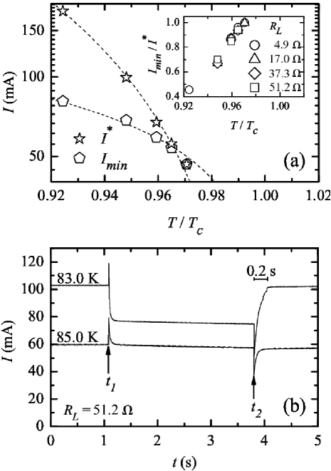
The results summarized in figure 3(b) illustrate how a superconducting microlimiter protects a circuit similar to the one of the inset of figure 1 from voltage faults. In these examples, is again the BS7 microbridge and (taking into account the resistance of the circuit electrical wires). For the curve measured at 83.0 K, the applied voltage was 5.8 V before () and after () a fault regime of 9.5 V. For the curve at 85.0 K, which is near , these values were 3.5 V and 7.5 V, respectively. As expected, the protection is excellent, whereas there is an overprotection when working well below . In both cases the recovery after the fault is achieved under current. This is another considerable practical advantage when compared to the superconducting limiters used in high power applications [1, 3]. These results suggest that optimal current limitation in superconducting electronics could be accomplished by their own conductive pathways after a proper design (e. g. by decreasing the width of the pathway at well-refrigerated selected locations), thus improving compactness.
4 Conclusions
High-temperature superconducting microbridges implemented with YBa2Cu3O7-δ thin films have been shown to be possible fault current limiters for microelectronic devices with some elements working at temperatures below the superconducting critical temperature and, simultaneously, under very low power conditions (below W). Our results demonstrate experimentally that by using substrates of high thermal conductivity, for instance sapphire, these microbridges may work in a regime where even relatively small faults induce their transition to highly-dissipative states, which dramatically increases their limitation efficiency. The criteria for good refrigeration and for optimal operation have been also obtained. Our results suggest that these superconducting microlimiters may be particularly useful in the important applications of low and high superconductors as SQUID or infrared detectors. In some applications this type of fault current superconducting microlimiters could be achieved by just decreasing the width of the superconducting current leads at well-refrigerated selected locations.
Acknowledgements
This work has been supported under Projects No. 2006/XA049 and No. 07TMT007304PR (XUGA-FEDER) and by Project. No. FIS2007-63709 (MEC-FEDER). J. A. L. F. acknowledges financial support from the Basque Government, through a grant from Education, Universities and Research Department.
References
- [1] See e. g., Proceedings of the NATO Advanced Study Institute 2000 Applications of Superconductivity (NATO Asi Series E-365) ed Weinstock H (Dordrecht: Kluwer Academic Publishers) p 247-415.
- [2] Bock J, Breuer F, Walter H, Elschner S, Kleinmaier M, Kreutz R and Noe M 2005 IEEE Trans. Appl. Supercond. 15 1955.
- [3] See e. g., Noe M and Steurer M 2007 Supercond. Sci. Technol. 20 R15, and references therein.
- [4] http://www.circuitprotection.com/polyswitch.asp
- [5] Viña J, González M T, Ruibal M, Currás S R, Veira J A, Maza J and Vidal F 2003 Phys. Rev. B 68 224506, and references therein.
- [6] Ruibal M, Ferro G, Osorio M R, Maza J, Veira J A and Vidal F 2007 Phys. Rev. B 75 012504.
- [7] Skocpol W J, Beasley M R and Tinkham M 1974 J. Appl. Phys. 45 4054.
- [8] See e. g., Gurevich A VI and Mints R G 1987 Rev. Mod. Phys. 59 941.
- [9] Poulin G D, Lachapelle J, Moffat S H, Hegmann F A, and Preston J S 1995 Appl. Phys. Lett. 66 2576.
- [10] Mosqueira J, Cabeza O, François M X, Torrón C and Vidal F 1993 Supercond. Sci. Technol. 6, 584.
- [11] Duron J, Grilli F, Antognazza L, Decroux M, Dutoit B and Fisher Ø 2007 Supercond. Sci. Technol. 20, 338.
- [12] See e. g., Chapman A J 1984 Heat Transfer (New York: MacMillan Publishing Company) chap 4.
- [13] Maza J, Ferro G, Veira J A and Vidal F 2008 Phys. Rev. B, 78, 094512.