Simulation studies of the high-energy component of a future imaging Cherenkov telescope array
Abstract
The current generation of Imaging Atmospheric telescopes (IACTs) has demonstrated the power of the technique in an energy range between 100 GeV up to several tens of TeV. At the high-energy end, these instruments are limited by photon statistics. Future arrays of IACTs such as CTA or AGIS are planned to push into the energy range beyond 100 TeV. Scientifically, this region is very promising, providing a probe of particles up to the ’knee’ in the cosmic ray spectrum and access to an unexplored region in the spectra of nearby extragalactic sources. We present first results from our simulation studies of the high-energy part of a future IACT array and discuss the design parameters of such an array.
Keywords:
Gamma-ray observations, AGIS, CTA, IACT, H.E.S.S., Ground-based Gamma-ray astronomy:
95.55.Ka, 95.85.Pw1 Introduction
At the highest energies accessible to current Cherenkov telescope arrays ( 50 TeV) the sensitivity limit is imposed by the small number of gamma-ray events which are collectible in reasonable ( 100 hours) exposures. The obvious method to increase sensitivity in this important energy domain is therefore to build an instrument with a collection area much larger than the m2 of IACT arrays such as H.E.S.S. and VERITAS. High energy arrays have been proposed in the past with the goal of achieving m2 (i.e. 10 km2) collection areas (Rowell et al., 2005). However, so far it is far from clear what the most cost effective telescope/camera/array layout for such an system would be. We have started investigations into the performance of a series of telescope arrays with different telescope dish sizes and field of view / pixel size with the aim of finding an optimal solution for achieving reasonable angular and energy resolution over a huge area - at manageable cost. This work is particularly relevant to the design of the high energy part of future ground-based arrays such as AGIS and CTA.
2 Design Considerations
2.1 Field of view
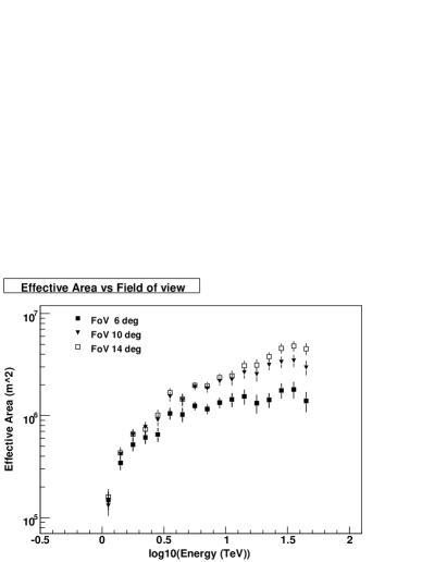
As a significant amount of Cherenkov light arrives on the ground at very large distances from the shower axis (i.e. well beyond the 100 m radius of the nominal “Cherenkov light pool”), the collection area of a single IACT (at the trigger level) is determined in the high energy limit only by the camera field of view (FoV). Current systems with FoV are sensitive only to showers with impact distances of m and hence reach asymptotic areas of m2. To achieve a 10 km2 collection area such an array would require at least 100 such telescopes. The alternative of fewer, more widely spaced telescopes with wider FoV is clearly attractive, but this approach is also challenging. Wide FoV systems may suffer from problems with optical aberrations, camera weight and obscuration. Detailed studies are needed, however, at this point it seems likely that the cost of telescopes may rise rather quickly beyond the 10∘ FoV suggested by (de La Calle Pérez and Biller, 2006) and offset the benefits of wider telescope separation and/or increased telescope multiplicity in individual events. As an example of how the effective area changes with increasing FoV see Figure 2.
2.2 Pixel Size
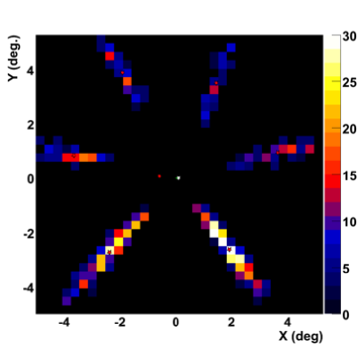
At large impact distance, air-shower images become rather long (see for example Figure 1), and the orientation of the image (and hence the shower direction for multiple images) can be determined reasonably well even with rather coarse (e.g. 0.3∘) pixels (de La Calle Pérez and Biller, 2006). However, the requirement to reject the hadronic background implies that pixel sizes much larger than the rms width of gamma-ray showers will result in a rapid decrease in sensitivity. Our studies have shown that there is a modest increase in angular resolution with smaller pixels at TeV energies (Funk and Hinton, 2008, these proceedings). However, since for a fixed FoV a decrease of a factor of a few in pixel size implies an order of magnitude increase in cost, it seems advantageous to utilise as large pixel sizes as possible (taking into account the rms width of gamma-ray showers as mentioned above). We note that only vertical showers are simulated here: the reduction in angular width of showers at larger zenith angles may necessitate the use of somewhat smaller pixels for a realistic observing program.
2.3 Telescope size
Large telescopes are unavoidably required to reach low energies and hence it has often been assumed that small telescopes are best for high energy studies (for reasons of cost-effectiveness). There are, however, two reasons for considering larger (m2) telescopes for studies beyond 10 TeV. Firstly, at a fixed energy the impact distance range of such telescopes is larger and at a fixed impact distance and energy, higher amplitude signals are recorded - potentially resulting in improved angular resolution and background rejection. Secondly, the cost of a wide FoV camera is considerable (even with large pixels) and it is unlikely that a design where the total cost of a telescope is completely dominated by the camera cost is optimum, i.e. larger telescopes could be used with little impact on the total cost of the array. Therefore, whilst at first glance a widely spaced array of small telescopes ( m2) with large fields of view and large pixels seems the best approach for a cost-optimised high-energy array, detailed studies of performance versus cost are needed to find the optimum array parameters. In the following we present the first steps in such a study.
3 Configurations
For our initial work we considered sub-arrays containing 3 or 7 telescopes – envisaged as components of a larger system. These arrays are arranged on a triangular grid with separations of both 300 m and 500 m. The CORSIKA air-shower program (Heck and The KASCADE Collaboration, 2001) is used together with a simplified telescope simulation/ analysis program based on idealised telescopes with square cameras and pixels. Vertical showers are considered for simplicity. Telescope diameters of 6 m and 10 m are considered. We estimate that the cost of a system of three 10 m telescopes with 0.2∘ pixels is similar to that of a seven telescope system with 0.3∘ pixels (both systems have a 10∘ FoV). The performance of these alternative systems are compared in the following section, i.e. a system with a few large telescopes and a system with more, but smaller, telescopes. An example event as seen by the (500 m separation) 6 m system is shown in Figure 1, illustrating the necessity of a large FoV for such impact distances, and that reasonable images can be obtained at such energies and impact distances even with large (0.3∘) pixels.
4 First Results on the performance
In a first step the effective areas for the two systems (3 large 10-m telescopes with 0.2∘ pixels and 7 smaller 6-m telescopes with 0.3∘ pixels) both with 10∘ fields of view have been compared.
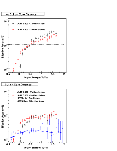
Figure 3 shows the resulting collection areas, demonstrating that even with these rather inexpensive systems a pre-cut effective area of well beyond m is possible (see top plot for the pre-cut effective areas). Cutting on the impact distance of the showers, i.e. using only those showers with reconstructed core position within 500 m from the center of the array, the effective area still reaches m (see Figure 3 bottom). As expected, the system of large telescopes performs better at the low energies (more light in the camera, therefore lower energy threshold), whereas at the high-energy end, the system of more small telescopes gives a larger effective area (due to the larger geometric area of the array). The lower panel of Figure 3 also shows the H.E.S.S. effective area curve (in blue), open circles are derived using our simplified scheme, filled squares as determined using a detailed telescope simulation, demonstrating the validity of our approach. It is evident from these curves, that even with the modest m dish-array an improvement in effective area of a factor of 5 over H.E.S.S. is possible. This effect is due both to the larger area covered by telescopes and to the increased field of view.
5 Angular Resolution
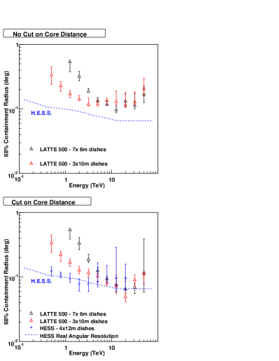
The next step in characterising the high-energy array performance is to assess the angular resolution for the two configurations, as shown in Figure 4. The H.E.S.S. angular resolution is again shown for comparison and to demonstrate the validity of our approach. As expected, the m array shows a poorer angular resolution than the array with the larger dishes and smaller pixels (basically due to the coarser pixelisation). In the bottom plot a cut on the reconstructed core distance has again been applied to select better reconstructed events. It should be noted, that these results are preliminary and the angular resolution will likely improve with a better adapted analysis method. Also evident from Figures 3 and 4 is that a real optimisation of the array is needed since there are obvious trade-offs between a larger effective area at the highest energies and the angular resolution of the system. It is evident from the comparison of the bottom plots in Figures 3 and 4 that with a simple cut on the impact distance of the shower, the angular resolution can be improved at the expense of a reduction in effective area.
6 Summary
This study is a first attempt to study how to optimise array parameters of the high-energy component of a future ground-based TeV gamma-ray instrument such as AGIS or CTA. It is evident from the results presented here that there are trade-offs between a large effective area and a good angular resolution and a careful optimisation (with input on science performance) has to be made to establish the optimum array design. In a next step, we will begin and investigation of background rejection power as a function of the primary design parameters of telescope size, field of view and pixel size.
References
- Rowell et al. (2005) G. Rowell, F. Aharonian, and A. Plyasheshnikov, ArXiv Astrophysics e-prints (2005), astro-ph/0512523.
- de La Calle Pérez and Biller (2006) I. de La Calle Pérez, and S. D. Biller, Astroparticle Physics 26, 69–90 (2006), arXiv:astro-ph/0602284.
- Funk and Hinton (2008, these proceedings) S. Funk, and J. A. Hinton (2008, these proceedings).
- Heck and The KASCADE Collaboration (2001) D. Heck, and The KASCADE Collaboration, “Hadronic Interaction Models and the Air Shower Simulation Program CORSIKA,” in International Cosmic Ray Conference, 2001, vol. 1 of International Cosmic Ray Conference, pp. 233–+.