Theory of tunnelling into a multi-band superconductor: decoherence and interference
Abstract
By an exact formulation of tunnelling into a multi-band superconductor in terms of Green’s functions, we demonstrate that the multi-band feature of the iron-based superconductors can lead to novel interference between Andreev reflections and decoherence effect of quasi-particles to Andreev reflections in a tunnelling junction. These effects depend on the relative sign of the gaps for s-wave pairing, and the sign of the Fermi velocities also matters for tunnelling along the nodal direction of d-wave gaps. Experimental probe of such effects could determine both the pairing symmetry and the relative sign of the gaps on different bands.
pacs:
74.20.Rp,74.45.+c,74.50.+rIntroduction: The discovery of iron-arsenide high-Tc superconductorshosono raises a new tide in the research of superconductivity.tide The immediate theoretical question to ask is what is the pairing symmetry, for which a group-theoretical analysis has been a first guide.sysmetry As for the pairing mechanism, a plausible scenario is that the strong spin fluctuations at wave vectors connecting the hole-like Fermi pockets near the -point and the electron-like pockets near the M-pockets centered at the corner of the reduced Brillouine zone (BZ) can lead to repulsive pair scattering interactions between the two sets of pockets, and therefore trigger a minus relative sign between gaps on the two sets of pockets.spinfluc The relative sign between the gaps is therefore a crucial factor to verify/falsify such scenarios. As for intra-pocket pairing symmetry, the situation is in hot debate. Angle-resoled photo-emission (ARPES) measurements find a more or less isotropic gap on each pocket, lending support to s-wave pairing.arpes Nuclear magnetic resonance (NMR)nmr and penetration depth measurementspenetrate see indications of nodes in the gap function, implying d-wave pairing. This is also supported by some specific heat measurements.specific heat However, more recent NMR and penetration depth experiments seem to favor node-less pairing.NMRnodeless In any case the relative sign is unknown. Tunnelling experiments provide signatures of both s-wave and d-wave pairing.tunnel This may be attributed to the sample quality, but we shall demonstrate that the interpretation of the tunnelling data requires extra care due to the underlying multi-band feature. The crucial idea is that tunnelling into a multi-band superconductor causes interference between the bands, an analogue of the well-known effect in multi-lead mesoscopic systems. Such an effect may encode the relative sign between the gaps, but is absent in, or only partially captured by existing theories of tunnelling.other theory Given the complex experimental situation, a theory that captures the multi-band effect exactly in tunnelling is emergently called for.
In the following we first sketch an exact formulation of tunnelling into a multi-band superconductor in terms of boundary Green’s functions on the leads, which we derive for practical cases. We then discuss the tunnelling behavior in junctions involving iron-based superconductors with all of the four Fermi pockets. We demonstrate that the multi-bands lead to novel destructive interference between Andreev reflections and decoherence effect of quasi-particles to Andreev reflections (both involving different bands). These effects depend on the relative sign of the gaps for s-wave pairing, and the sign of the Fermi velocities also matters for tunnelling along the nodal direction of d-wave gaps. Experimental probe of such effects could therefore determine both the pairing symmetry and the relative sign of the gaps on different bands.
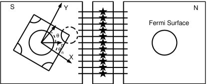
Exact formulation: Suppose we are dealing with an N-S junction with a superconductor carrying multi-bands on the left-hand lead (L), a normal metal on the right-hand lead (R), and a scattering center that couples to the -band of the leads with amplitudes . The junction geometry is illustrated in Fig.1. In our case on the L-lead and on the R-lead. The tunnelling current at bias voltage can be written as,tunnel theory
| (1) |
where is the retarded (advanced) Green’s function on the scattering center, with (for and applied separately for the retarded and advanced cases) as the self energy correction to the scattering center due to coupling to the leads so that . Here ’s are Pauli matrices in the Nambu space, and the doubly-numbered subscripts in Eq.(1) refer to the matrix elements. Moreover, is the Green’s function in the -band at the open boundary before attaching the scattering center. The first term in Eq.(1) describes quasiparticle contribution, while the second is due to Andreev reflection which is nonzero if contains off-diagonal components. Throughout this work for retarded/advanced Green’s functions, which is left implicit for notational convenience.
Eq.(1) can be reached by intuitive arguments along the line of Blonder-Tinkham-Kapwijk (BTK).BTK The matrix describes the transmission probability tunnel theory for particles/holes from R- to L-lead. For electron transmission, the probability flux is , with the group velocity. Multiplied by the number of modes within a momentum interval , the total flux is within an energy interval . In equilibrium this must balance the counter flux from L to R. Under a bias voltage, an electric current arises as . Similarly, the hole transmission contributes a current , where accounts for the positive charge. The off-diagonal parts of describes incoming electrons/holes from R transmitted as outgoing holes/electrons on L. This does not contribute to current, and in fact cancels out due to charge conservation. On the other hand, one can take the Nambu components as generalized channels, by which pairing is nothing but channel hybridization. On the R-lead, such inter-channel transmission is exactly the Andreev reflection. In the spirit of , the probability reads . This contributes an electric current , where the factor of accounts for the charge transported to L during each Andreev reflection. Similarly, for incoming holes reflected as outgoing electrons, the electric current is . Collecting everything and integrating over we arrive at Eq.(1).
We emphasize that at this stage the formulation is exact, and all possible interference effects in our case are exactly reflected in the self-energies that combines the contributions from all bands coherently. To apply the theory we need the boundary Green’s function, the derivation of which is sketched as follows.
Boundary Green’s functions: Consider an arbitrary band in a semi-infinite system with a boundary normal relative to the direction of the BZ (the iron-arsenide-iron direction), as illustrated in Fig.1. We assume circular Fermi surface, and near the Fermi momenta we fix the conserved transverse component , where is the angle between and . For the M-pockets, , the transverse projection of , should be added. We then map the longitudinal degrees of freedom (near the Fermi angles and ) to a semi-infinite one-dimensional system described by the Andreev equations,BTK demanding that the wave function vanishes a unit distance (the lattice constant, for example) beyond the boundary. These eigen functions and energies are then used to construct the Green’s function in a standard manner. Another approach is the T-matrix theory for an infinite plane with an infinite barrier along a line.tmatrix We get the same results using both approaches under the quasi-classical approximation.
For the s-wave case, the result is independent of : where is the normal state density of states (DOS) with the Fermi velocity, is a Friedel-like factor due to the open boundary, and , in which (for retarded/advanced cases) in practice. Here is the step function.
For the d-wave case, we consider only two practical cases: If is along the anti-nodal direction, , and we find similar to the s-wave case, except for the -dependence in the pairing function.
In contrast, if is along the nodal direction, , and we find with , where if is outward (inward) to the center of the Fermi pocket. The pole at is a particle-hole mixing bound state due to the nodal boundary.boundstate Notice that the off-diagonal component in depends on both the sign of the gap and the electron/hole nature of the Fermi pocket, leading to interesting consequence for interference in the Andreev reflection to be discussed. Finally the Green’s function in the normal lead can be obtained by simply set .
The above results are applied separately for in each band, which is then substituted into Eq.(1) for the conductance calculation.
Application to junctions with iron-based superconductors: We define for the four bands on the L-side and for on the normal R-side, with the Fermi radius of the -pocket. To simplify the discussion we assume for all bands on the L-lead, and set and for a range of values of ( corresponds to the transparent/tunnelling limit). We also set as the unit of energy. For the gap amplitudes on the four pockets we set and , with and in line with existing experiments. We assume that the gaps on the -pockets are in-phase, so are those on the -pockets, but the relative sign between the - and -pockets is left free for discussion.
We consider wide junctions, for which the conductance is calculated by Eq.(1) (in the zero temperature limit) for each conserved transverse momentum (in which should be added for the M-pockets). The channels unmatched by should be shutoff. The total conductance is then given by per unit area.
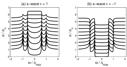
We first consider tunnelling along . Here , and can be matched to all Fermi surfaces under our assumption, because of which we expect novel effects. For the s-wave case, by using derived above and under the given assumptions, we get . a) In the in-phase case , the -component in is left intact, and we expect Andreev contribution. However, quasiparticles at acts as dissipative source for (and therefore reduce) the Andreev reflections associated with the larger gap. This is a decoherence effect, and is seen as the dips in Fig.2(a) at energies in between the two gap edges. b) In the anti-phase case , the off-diagonal component cancels out in and consequently in . According to Eq.(1) the Andreev contribution disappears. This is exactly the anticipated destructive interference effect among Cooper pairs transported to the L-side during Andreev reflections on the R-side. Withinin the smaller gap there are no quasi-particles either so that the conductance is completely zero at any level of transparency. This behavior is shown in Fig.2(b). For , quasi-particles from - and -bands start to contribute. Of course, both effects becomes less significant in the tunnelling limit where quasi-particles dominate.
For the -wave case is the antinodal direction. According to the previous derivation of , the structure of is similar to that in the s-wave case, except that should be replaced by . The decoherence effect for in Fig.3(a) is less visible because of the size variation in the d-wave gap function. However, the destructive interference effect for in Fig.3(b) is still obvious at .
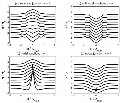
For the -wave case, is the nodal direction. Here the structure of is very different, , where . The extra minus sign before comes from the fact that the relative sign of the Fermi velocities is minus for the - and M-pockets. Therefore we expect destructive interference for instead of . a) The result for is presented in Fig.3(c). For the conductance is similar to the corresponding line in Fig.2(a). With decreaing , a central peak shows up and we checked numerically that the Andreev contribution dominates, due to the fact that the bound state is a particle-hole mixture. b) For , the off-diagonal component cancels out in , and the results are shown in Fig.3(d). For the conductance is of broad -shape. The normal (i.e., in the absence of particle-hole mixing off-diagonal component) bound-state does not show up here because it has zero group velocity. In the tunnelling limit , the normal bound state eventually shows up as a central peak, since in this limit the DOS on the L-lead is measured. In addition, no coherence peak occur in (c) and (d) even in the tunnelling limit, due to the fact that no singularity arise at the gap edge in . The absence of coherence peaks was possibly observed.tunnel
For tunnelling along , the two sets of pockets match that of the normal lead at different momenta, so that the - and -pockets can be treated independently. Since within each set of bands the two gaps are in-phase, the effect of multi-gaps can be traced in the previous discussion.
We add without going into details that in-plane point-contact on wide boundary is also helpful. Here one simply averages the Green’s function over first to get the on-site Green’s function, which is then substituted into Eq.(1). There is no momentum matching constrain. We see that the off-diagonal part of survives for the s-wave case and the d-wave anti-nodal tunnelling case, in which both interference and decoherence effect can occur. In the case of d-wave nodal tunnelling, the off-diagonal part cancels out. Furthermore, even out-of-plane tunnelling is useful. Here one simply use the on-site Green’s function in an infinite plane: . For s-wave gaps, the off-diagonal part still survives and interference/decoherence occurs, while it cancels out by symmetry for all kinds of d-wave gaps and only quasi-particles contribute to the conductance.
We remark that in the real system, the sizes of the four Fermi pockets differ slightly. The coupling between the scattering center and each band may also differ. These factors may weaken the effects discussed so far, but should still be discernable.
Conclusions: We presented an exact formulation of tunnelling into a multi-band superconductor, and derived the relevant boundary Green’s functions. Applying to iron-based superconductors we demonstrate that the multi-band feature can lead to novel destructive interference between Andreev reflections and decoherence effect of quasi-particles to Andreev reflections (both involving different bands) in a tunnelling junction. These effects depend on the relative sign of the gaps for s-wave pairing, and the sign of the Fermi velocities also matters for tunnelling along the nodal direction of d-wave gaps. We propose that in-plane wide junction and point-contact junction, as well as out-of-plane contact junction can be used to probe such effects, and therefore provide decisive information on the pairing symmetry and the relative sign of the gaps on the various bands.
While finalizing this work, we become aware of some recent interesting theories.recent
Discussion with Bai-Geng Wang is highly appreciated. This work was supported by NSFC 10325416 and 10734120, the Fok Ying Tung Education Foundation No.91009, the Ministry of Science and Technology of China (under the Grant No. 2006CB921802 and 2006CB601002) and the 111 Project (under the Grant No. B07026).
References
- (1) Y. Kamihara, et al, J. Am. Chem. Soc 130, 3296 (2008).
- (2) X. H. Chen et al., Nature 453, 761 (2008); H. H. Wen et al., Europhys. Lett. 82, 17009 (2008); Z. A. Ren et al., Europhys. Lett. 83, 17002 (2008); G. F. Chen, et al, Phys. Rev. Lett 100, 247002 (2008); R. H. Liu, et al, ibid 101, 087001 (2008); M. Rotter, et al, Phys. Rev. B 78, 020503(R) (2008); A. S. Sefat, et al, Phys. Rev. Lett 101, 117004 (2008).
- (3) Z. H. Wang, et al, arXiv:0805.0736; Y. Wan and Q. H. Wang, arXiv: 0805.0923; Y. Zhou, W. Q. Chen and F. C. Zhang, Phys. Rev. B 78, 064514 (2008); Wen-Long You, Shi-Jian Gu, Guang-Shan Tian, and Hai-Qing Lin, Phys. Rev. B 79, 014508 (2009).
- (4) I. I. Mazin, D. J. Singh, M. D. Johannes, and M. H. Du, Phys. Rev. Lett. 101, 057003 (2008); K. Kuroki, et al, ibid 101, 087004 (2008); Zi-Jian Yao, Jian-Xin Li, and Z. D. Wang, arXiv: 0804.4166; F. Wang, et al, arXiv: 0807.0498; A.V. Chubukov, D. V. Efremov and I. Eremin, Phys. Rev. B 78, 134512 (2008).
- (5) H. Ding, et al, Europhys. Lett 83, 47001 (2008); K. Nakayama, et al, arXiv: 0812.0663; L. Zhao, et al, Chin. Phys. Lett 25, 4402 (2008); T. Kondo, et al, Phys. Rev. Lett 101, 147003 (2008); D. V. Evtushinsky, D. S. Inosov, V. B. Zabolotnyy et al, arXiv: 0809.4455.
- (6) H. J. Grafe, et al Phys. Rev. Lett 101, 047003 (2008); K. Matano, et al, Europhys. Lett 83, 57001 (2008); Y. Nakai, et al, J. Phys. Soc. Jpn 77, 073701 (2008); H. Mukuda, et al, J. Phys. Soc. Jpn 77, 093704(2008).
- (7) C. Ren, et al, arXiv: 0804.1726; H. Luetkens, et al, Phys. Rev. Lett 101, 097009 (2008); K. Ahilan, et al, Phys. Rev. B 78, 100501(R) (2008); X. L. Wang, et al, Arxiv: 0808.3398; R. T. Gordon, et al, arXiv: 0810.2295; R. T. Gordon, et al, arXiv: 0812.3683.
- (8) G. Mu, et al, Chin. Phys. Lett 25, 2221 (2008); G. Mu, et al, Arxiv: 0808.2941.
- (9) N. Terasaki, et al, J. Phys. Soc. Jpn 78, 013701 (2009); H. Fukazawa, et al, arXiv: 0901.0177; K. Hashimoto, et al, Phys. Rev. Lett 102, 017002 (2009); L. Malone, et al, arXiv: 0806.3908; C. Martin, et al, arXiv: 0807.0876; M. Hiraishi, et al, arXiv: 0812.2069;
- (10) L. Shan, et al, Europhys. Lett. 83 57004 (2008); T. Y. Chen, et al, Nature 453, 1224 (2008); K. A. Yates, et al, Supercond. Sci. Technol. 21 092003 (2008); P. Samuely, et al, Supercond. Sci. Technol. 22 014003 (2009); Y. L. Wang, Supercond. Sci. Technol. 22 015018 (2009); M. C. Boyer, et al, arXiv: 0806.4400; O. Millo, et al, Phys. Rev. B 78, 092505 (2008); R.S. Gonnelli, et al, arXiv: 0807.3149; P. Szabo, et al, arXiv:0809.1566; D. Daghero, et al, arXiv: 0812.1141.
- (11) J. Linder and A. Sudbø, Phys. Rev. B 79, 020501(R) (2009); H. Y. Choi and Y. Bang, arXiv: 0807.4604; X. Y. Feng and T. K. Ng, arXiv: 0812.1068.
- (12) Y. Meir and N. S. Wingreen, Phys. Rev. Lett 68, 2512 (1992). Here the authors discussed tunnelling in normal state multi-channel systems.
- (13) G. E. Blonder, M. Tinkham, and T. M. Klapwijk, Phys. Rev. B 25, 4515 (1982); S. Kashiwaya, Y. Tanaka, M. Koyanagi and K. Kajimura, Phys. Rev. B 53, 2667 (1996).
- (14) Qiang-Hua Wang and Z. D. Wang, Phys. Rev. B 69, 092502 (2004).
- (15) C. R. Hu, Phys. Rev. Lett. 72, 1526 (1994); For a review and the effects in tunnelling, see, e.g., S. Kashiwaya and Y. Tanaka, Rep. Prog. Phys. 63, 1641 (2000).
- (16) A.A. Golubov, et al, arXiv: 0812.5057; M. A. N. Araujo and P. D. Sacramento, arXiv:0901.0398; S. Onari and Y. Tanaka, arXiv: 0901.1166.