Effect of isomers on quantum transport through molecular
bridge system
Santanu K. Maiti1,2,∗
1Theoretical Condensed Matter Physics Division,
Saha Institute of Nuclear Physics,
1/AF, Bidhannagar, Kolkata-700 064, India
2Department of Physics, Narasinha Dutt College,
129, Belilious Road, Howrah-711 101, India
Abstract
Quantum transport for different models of isomer molecules attached to two semi-infinite leads is studied on the basis of Green’s function technique. Electronic transport properties are significantly affected by (a) the relative position of the atoms in these molecules and (b) the molecule-to-lead coupling strength of these molecular bridge systems.
PACS No.: 73.23.-b; 73.63.-b; 81.07.Nb
Keywords: Green’s function; Isomer; Conductance; - characteristic.
∗Corresponding Author: Santanu K. Maiti
Electronic mail: santanu.maiti@saha.ac.in
1 Introduction
Molecular electronics and transport have attracted much more attention since molecules constitute promising building blocks for future generation of electronic devices. The transport through molecules was first studied theoretically in [1]. Later several numerous experiments [5, 6, 7, 8, 9] have been performed through molecules placed between two electrodes with few nanometer separation. Full quantum mechanical treatment is required to characterize the transport through molecules. Some ab initio calculations [2, 3, 4] are also used to study the current-voltage characteristics of a molecule. Electrical conduction through isomer molecules strongly depends on the relative position of the atoms in molecules and their coupling strength to the two leads, namely, left lead and right lead. Here we describe theoretically the electron transport in some specific models of isomer molecules. Based on the scanning probe technique measurement, conductance of molecular systems is directly possible [10, 11, 12, 13, 14, 15]. Theoretically there exist several formulations [16, 17, 18, 19, 20, 21, 22] for the calculation of conductance based on Landauer formula and the seminal paper of Aviram and Ratner [1]. At much low temperatures and low bias voltages the electron transport becomes coherent through the molecule. Here we assume that the dissipation and equilibration processes occur only in the two contacting leads and this approximation enables to describe the propagation of an electron by means of single particle Green’s function. This theory is much more flexible than any other theoretical approach and also applicable to any system described by a Hamiltonian with a localized orbital basis. By using this method the electronic transport properties of any system can be studied very easily with a very small computational cost. In that case we have to know only the Hamiltonian matrix for the molecule but no need to know anything about the electronic wave function.
Here, we investigate the conductance () and current-voltage (-) characteristics of three different isomer molecules and compute the effect of these isomers on the electrical conduction.
The present article is organized as follows. In Section , we describe the formulation of conductance by calculating the transmission probability and current for any finite size conducting system attached to two semi-infinite metallic leads by the use of Green’s function technique. Section describes the conductance and current-voltage characteristics of single isomer molecules. Finally, we conclude our results in Section .
2 Formulation of , and : Green’s function technique
Here we give a brief description for the calculation of transmission probability (), conductance () and current () through a finite size conducting system attached to two semi-infinite metallic leads by the use of Green’s function technique.
Let us first consider a one-dimensional conductor with number of atomic sites (array of filled circles) connected to two semi-infinite leads, left lead and right lead as shown in Fig. 1. The conducting system in between the two leads

can be an array of some quantum dots, or a single molecule, or an array of some molecules, etc. At low voltages and low temperatures, the conductance of a conductor can be written through the Landauer conductance formula as [23],
| (1) |
where is the conductance and is the transmission probability of an electron through the conductor. This transmission probability can be expressed in terms of the Green’s function of the conductor and the coupling of the conductor to the two leads in the following way,
| (2) |
where and are respectively the retarded and advanced Green’s function of the conductor. and are the coupling terms between the conductor and the two leads. For the complete system, i.e., the system with the conductor and the two leads, the Green’s function is defined as,
| (3) |
where . is the energy and is a very small number which can be put as zero in the limiting approximation. The above Green’s function corresponds to the inversion of an infinite matrix which consists of the full system. It can be partitioned into different sub-matrices that correspond to individual sub-systems.
The Green’s function for the conductor can be effectively expressed in the form,
| (4) |
where is the Hamiltonian of the conductor sandwiched between the two leads. The Hamiltonian of the conductor in the tight-binding framework can be written within the non-interacting picture in this form,
| (5) |
where () is the creation (annihilation) operator of an electron at site , ’s are the site energies and is the nearest-neighbor hopping strength. In Eq. 4, and are the self-energy terms due to the semi-infinite leads. and are respectively the Green’s function for the left and right leads. and are the coupling matrices and they will be non-zero only for the adjacent points in the conductor, and as shown in Fig. 1, and the leads respectively. The coupling terms and for the conductor can be calculated through the expression [23],
| (6) |
where and are the retarded and advanced self-energies respectively and they are conjugate with each other. Datta et al. [24] have shown that the self-energies can be expressed in this form,
| (7) |
where are the real parts of the self-energies for the two leads. The imaginary parts of the self-energies represent the broadening of the energy level due to the coupling of the conducting system with the two leads respectively. By calculating some algebra these real and imaginary parts of the self-energies can also be determined in terms of coupling strength () between the conductor and the two leads, injecting energy () of the transmitting electrons and hopping strength () between nearest-neighbor sites in the leads. Thus the coupling terms and can be written in terms of the retarded self-energy as,
| (8) |
Thus by calculating the self-energies due to the left and right leads the coupling terms and can be easily obtained and then the transmission probability () will be calculated from the expression as mentioned in Eq. 2.
Since the coupling matrices and are non-zero only for the adjacent points in the conductor, and as shown in Fig. 1, the transmission probability can be expressed in the following way,
| (9) |
For the sake of simplicity, here we assume that the entire voltage () is dropped across the conductor-electrode interfaces.
The current through the bridge system can be written in the following form [23],
| (10) |
where is the Fermi energy of the conductor. Using the expression of as in Eq. 9 the final form of will be,
| (11) | |||||
Eq. 1, Eq. 9 and Eq. 11 are the final working formulae for the calculation of conductance and current-voltage characteristics respectively for any finite size conducting system connected to two semi-infinite leads.
Here, we shall describe conductance-energy and current-voltage characteristics by using the above formulations for some specific models of single isomer molecules. Throughout the paper, we use the units where .
3 Conductance and current-voltage characteristics of isomer molecules
Electron transport is strongly affected by the relative position of the atoms in single isomer molecules, and, to describe this effect we consider three different models of isomer molecule. Figure 2 corresponds to the schematic geometry of the three different isomer

molecules. They are respectively defined as pyridazine, pyrazine and pyrimidine, where relative position of the two nitrogen atoms changes accordingly as shown in the figure. These single molecules are connected to two semi-infinite leads by thiol (S-H) groups (not shown here in the figure). In actual experimental setup, two leads made from gold (Au) are used and molecule attached to the leads by thiol (S-H) groups in the chemisorption technique where hydrogen (H) atoms remove and sulfur (S) atoms reside. Here we assume that the molecules are connected to the two leads via sulfur atoms by removing the extreme left and right hydrogen atoms of each molecule as shown in Fig. 2.
It should be noted that the electron transport is strongly affected by the molecule to lead coupling strength and in this article we shall describe the isomeric effect on electron transport both for the weak and strong

molecule-lead coupling limits. The weak coupling limit is mentioned through the condition , while the strong coupling limit is denoted as . is the molecule to lead coupling strength and is the hopping strength between nearest-neighbor site in the molecule. Throughout the paper, we set the values of these parameters in the weak coupling limit as , , and, for the strong coupling limit these parameters are taken as , . Now, we try to characterize the conductance-energy and current-voltage characteristics of these single isomer molecules.
In Fig. 3, we plot the conductance variation as a function of energy of these three isomer molecules for the weak molecule to lead coupling limit. Figures 3(a), (b) and (c) correspond to the conductance variation of pyridazine, pyrazine and pyrimidine molecules

respectively. The conductance shows oscillatory behavior with sharp resonant peaks for some particular energy values, while for all other energy values it almost vanishes. This behavior can be understood as follows. Transmission of an electron through a molecule takes place only when the incident energy matches with anyone of the energy eigenvalues of the molecule. For this particular energy value the electron transmits almost ballistically from the source to drain, and accordingly, conductance shows a sharp peak. Now the electrons are carried from the left lead to right lead through isomer molecules and hence the electron waves propagating along the two arms of the ring may suffer a phase shift between themselves, according to the result of quantum interference between the various pathways that the electron can take. Therefore, the probability amplitude of the electron across the ring becomes strengthened or weakened. It emphasizes itself especially as transmittance cancellations, some peaks do not reach to unity anymore, and anti-resonances in the transmission (conductance) spectrum. From Fig. 3(a) and Fig. 3(b) it is observed that at
resonances the conductance shows the value , i.e., for these resonances transmission probability goes to unity (since from Landauer formula we get by putting ). On the other hand, Fig. 3(c) shows that the conductance peak does not reach the value anymore. Though all these three molecules are attached symmetrically to the two leads, yet the probability amplitude across the pyrimidine molecule decreases compared to the other two molecules. So it can be emphasized that the electron transmission is strongly affected by the relative position of the two nitrogen atoms in these isomer molecules. Thus, different molecular structure can significantly affect the transport property even if they are isomer.
Another important feature observed from this Fig. 3 is that, for the pyrazine (Fig. 3(b)) and pyrimidine (Fig. 3(c)) molecules electron transmission starts at very low energy value, i.e., for low applied bias voltage . On the other hand, the pyridazine molecule starts electron transmission at quite higher energy value (see Fig. 3(a)). Thus, the threshold bias voltage for electron transmission also depends on the relative position of the two nitrogen atoms in these isomers.
To investigate the effect of conductance behavior in strong molecule to lead coupling limit, we plot the results of as a function of energy for these three isomer molecules in Fig. 4, where (a), (b) and (c) are respectively for the pyridazine, pyrazine and pyrimidine molecules. From these curves it is observed that the resonant peaks get substantial widths and electron transmission takes place for wide range of energy values through these molecular bridge systems. This is due to the substantial broadening of the molecular energy levels caused by the strong coupling of the molecule to the two semi-infinite leads [23]. These effects have strong dependence on the current-voltage characteristics which we are going to discuss in the following parts.
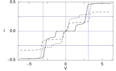
Now, we study the current-voltage characteristics of these molecular bridge systems. The current is computed by the integration procedure of the
transmission function . The behavior of the transmission function with energy is exactly similar (differ only in magnitude by the factor due to the existence of the relation ) to that as presented in Fig. 3 and Fig. 4. Figure 5 represents some current-voltage characteristics of the three molecules in the weak molecular coupling limit, where the solid, dotted and dashed lines give the current for the pyridazine, pyrazine and pyrimidine molecules, respectively. The current shows staircase-like behavior with sharp steps. This is due to the discreteness of the molecular resonances as shown in Fig. 3. From this figure it is clearly observed that, both the pyrazine and pyrimidine molecules show finite non-zero value of current (dotted and dashed curves) for very small applied bias voltages, while the pyridazine molecules gives non-zero value of current (solid curve) at higher bias voltages.
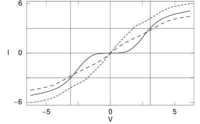
In the presence of strong molecule to lead coupling limit, the staircase-like behavior disappears and current varies quite continuously with the applied bias voltage. The variation of the current for these three isomer molecules in the strong coupling limit is plotted in Fig. 6, where the solid, dotted and dashed lines correspond to the same meaning as earlier. For this coupling limit, molecular resonances get substantial width (Fig. 4) and since the current is computed by the integration procedure of the transmission function , it gets a continuous variation with the applied bias voltage . Similar to the weak coupling case, the pyrimidine molecule gives non-zero value of the current at sufficient higher bias voltages compared to the other two molecules in this strong coupling case. Another important observation is that, in the strong coupling limit current amplitude becomes very large than that of the current amplitude in the weak coupling limit for these molecular bridge systems.
4 Concluding remarks
To conclude, we have investigated the effect of isomers and molecule to lead coupling strength on electron transport through some models of different types of isomer molecules. Depending on the relative position of the two nitrogen atoms in these isomer molecules, threshold bias voltage for electronic conduction changes which provides an important signature for the fabrication of different molecular bridge systems. The conductance shows fine resonant peaks which gives the staircase-like behavior with sharp steps in current for the weak coupling limit, while in the strong coupling limit, the resonant peaks get substantial widths, and accordingly, the current varies almost continuously with the applied bias voltage.
Acknowledgments
It is my pleasure to thank Atikur Rahman and Prof. S. N. Karmakar for many helpful comments and suggestions.
References
- [1] A. Aviram and M. Ratner, Chem. Phys. Lett. 29 (1974) 277.
- [2] M. Di Ventra, S. T. Pantelides, and N. D. Lang, Phys. Rev. Lett. 84 (2000) 979.
- [3] W. W. Cheng, H. Chen, R. Note, H. Mizuseki, and Y. Kawazoe, Physica E 25 (2005) 643.
- [4] W. W. Cheng, Y. X. Liao, H. Chen, R. Note, H. Mizuseki, and Y. Kawazoe, Phys. Lett. A 326 (2004) 412.
- [5] T. Dadosh, Y. Gordin, R. Krahne, I. Khivrich, D. Mahalu, V. Frydman, J. Sperling, A. Yacoby, and I. Bar-Joseph, Nature 436 (2005) 677.
- [6] R. M. Metzger et al., J. Am. Chem. Soc. 119 (1997) 10455.
- [7] C. M. Fischer, M. Burghard, S. Roth, and K. V. Klitzing, Appl. Phys. Lett. 66 (1995) 3331.
- [8] J. Chen, M. A. Reed, A. M. Rawlett, and J. M. Tour, Science 286 (1999) 1550.
- [9] M. A. Reed, C. Zhou, C. J. Muller, T. P. Burgin, and J. M. Tour, Science 278 (1997) 252.
- [10] S. Hong, W. Tian, J. Henderson, S. Datta, C. P. Kubiak, and R. Reifenberger, Superlat. Microstruct. 28 (2000) 289.
- [11] S. J. Tans, R. M. Verschueren, and C. Dekker, Nature 393 (1998) 49.
- [12] M. Bockrath, D. H. Cobden, P. L. McEuen, N. G. Chopra, A. Zettl, A. Thess, and R. E. Smalley, Science 275 (1997) 1922.
- [13] Z. J. Donhauser et. al., Science 292 (2001) 2303.
- [14] X. D. Cui, A. Primak, X. Zarate et. al., Science 294 (2001) 571.
- [15] J. H. Schon, H. Meng, and Z. N. Bao, Science 294 (2001) 2138.
- [16] R. Baer and D. Neuhauser, Chem. Phys. 281 (2002) 353.
- [17] R. Baer and D. Neuhauser, J. Am. Chem. Soc. 124 (2002) 4200.
- [18] D. Walter, D. Neuhauser, and R. Baer, Chem. Phys. 299 (2004) 139.
- [19] K. Walczak, Cent. Eur. J. Chem. 2 (2004) 524.
- [20] K. Walczak, Phys. Stat. Sol. (b) 241 (2004) 2555.
- [21] Molecular Electronics-Science and Technology, edited by A. Aviram and M. Ratner (N. Y. Acad. Sci., N. Y., 1998) (volume 852 of Ann. N. Y. Acad. Sci.).
- [22] S. Roth and C. Joachim, Atomic and Molecular Wires (Kluwer, Dordrecht, 1997).
- [23] S. Datta, Electronic transport in mesoscopic systems, Cambridge University Press, Cambridge (1997).
- [24] W. Tian, S. Datta, S. Hong, R. Reifenberger, J. I. Henderson, and C. I. Kubiak, J. Chem. Phys. 109 (1998) 2874.