Summary of One Year Operation of the EUDET CMOS Pixel Telescope
Abstract
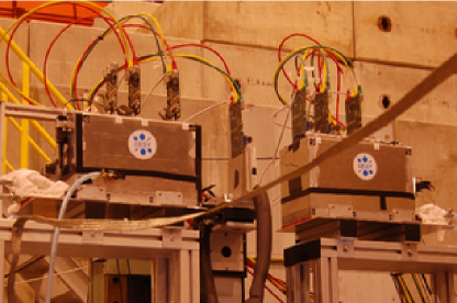
Within the EUDET consortium a high resolution pixel beam telescope is being developed. The telescope consists of up to six planes of monolithic active pixel sensors. A flexible data acquisition environment is available for the telescope and the system is equipped with all the required infrastructure. Since the first installation of a demonstrator telescope in 2007, it has been extensively tested and used by various detector R&D groups. The results of test beam measurements are described here, demonstrating the telescope performance.
1 Introduction
The EUDET project [2], which is supported by the EU in the 6th Framework Programme (FP6), aims to provide infrastructure for the R&D of detector technologies towards the international linear collider. Within the EUDET project the JRA1 activity works on the improvement of test beam infrastructure. For this purpose, a high resolution pixel telescope is being developed. The design goals include a high position resolution (m) and readout rate of 1 kHz.
The construction of the telescope is performed in two steps. In June 2007, the so-called demonstrator telescope was installed for the first time using an analog readout. After the first successful operation at the electron beam at DESY, the demonstrator was transported to CERN and its performance was studied using 180 GeV hadrons at the SPS [3]. After the first successful integration of a Device Under Test (DUT) in September 2007 [4], the demonstrator telescope has been used by various groups and was improved continuously.
2 Description of the Telescope
2.1 The sensor
The MimoTEL sensor, used for the demonstrator telescope, is a Monolithic Active Pixel Sensor (MAPS) produced in the AMS 0.35 OPTO process. It is subdivided in four sub-arrays of 64256 pixels with a pixel pitch of 3030 m2, resulting in a sensor size of 7.77.7 cm2. A high resolution sensor with a pitch of 10 m can be located close to the DUT to further increase the resolution.
2.2 The DAQ system
The DAQ system can be summarised as follows: All data from the sensors is transferred via frontend boards to an intermediate readout and data reduction board called EUDRB (EUDET Data Reduction Board) [5]. The EUDRB board allows the first steps of the data processing online to be performed. Two I/O busses are supported: For the telescope the VME64x bus is used to allow high speed data transfer and synchronous operation with other devices while an USB2.0 interface is foreseen for standalone testing. A mother / daughter board scheme has been followed to maximise the flexibility. All computing and memory elements are located on the motherboard while the sensor specific components have been implemented on removable and interchangeable daughter cards.
Another important component of the DAQ system is the trigger logic unit (TLU) [7]. It is considered as the replacement for a NIM crate and can generate any coincidence or anticoincidence of four trigger scintillators. Six LVDS and two TTL interfaces are provided. Furthermore, the TLU generates event numbers and time stamps. It is connected by USB2.0 to a control PC running the Linux operating system that is in turn connected to the main DAQ PC through gigabit ethernet.
A custom DAQ system named EUDAQ has been implemented in C++ [8]. Several producer tasks communicate with a global run control using sockets. These producer tasks connect to the hardware of the beam telescope, to the TLU and eventually to the DUT. Data from all producers is sent to the central data collector and can be monitored by several processes. An online monitor, based on the ROOT framework, shows online data quality monitoring histograms and a process to collect log messages is available. EUDAQ runs on MacOS, Linux and Windows using cygwin.
2.3 The offline analysis software
For the offline reconstruction of track positions in the DUT the software package EUTelescope [9] has been developed, which is implemented as a set of Marlin processors [10]. This design allows to integrate the DUT data at different steps of the analysis chain. Furthermore, the package can be executed on the Grid to allow a fast processing of large datasets.
3 Test beam results
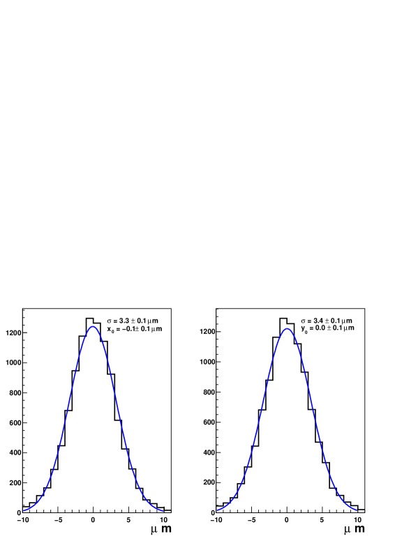
Figure 2 shows the residuals of the tracks in the middle out of 5 sensor planes. Here the middle telescope sensor acts as DUT while the other planes are used to predict the track positions in the DUT. The observed width is consistent with the expectation for the given telescope geometry assuming a position resolution of 3.0 m for the DUT as well as for the other sensors used to fit tracks. Also, measurements at DESY using 3 and 6 GeV electrons based on an extrapolation to infinite energy are in agreement with this sensor resolution. The telescope was used by 7 different detector R&D groups for resolution studies of their own systems. All of them were satisfied with the telescope performance and are planning to use it again in 2009.
4 Summary
The demonstrator telescope has been running successfully during several test beam measurements for about one year. Modularity was one of the most important design aspects for the DAQ hardware and software as well as for the offline analysis package. The analysis of test beam data shows that the performance of the demonstrator fulfils the expectations. An increased active area and zero suppression on the sensors will be offered by the final telescope which is under construction. Groups interested in using the device are welcome to contact the EUDET consortium.
References
-
[1]
Presentation:
http://ilcagenda.linearcollider.org/contributionDisplay.py?contribId=165&sessionId=21&confId=2628 - [2] More information about the EUDET project can be found on www.eudet.org
- [3] A. Bulgheroni, EUDET-Report-2007-06 (2007).
- [4] L. Reuen, EUDET-Memo-2007-40 (2007).
- [5] A. Cotta Ramusino, EUDET-Memo-2007-36 (2007).
- [6] A.F. Zarnecki and P. Niezurawski, EUDET-Memo-2007-01, arXiv:physics/0703058v1 (2007).
- [7] D. Cussans, EUDET-Memo-2007-02 (2007).
-
[8]
E. Corrin, D. Haas and M. Pohl, EUDET-Memo-2006-07 (2006);
D. Haas, Proc. of the LCWS’07, Hamburg, EUDET-Report-2007-08 (2007). - [9] A. Bulgheroni, T. Klimkovich, P. Roloff and A.F. Zarnecki, EUDET-Memo-2007-20 (2007).
- [10] F. Gaede, J. Engels, EUDET-Report-2007-11 (2007).