Impact of octahedral rotations on
Ruddlesden–Popper phases of antiferrodistortive perovskites
Abstract
This work presents the most detailed and extensive theoretical study to date of the structural configurations of Ruddlesden–Popper (RP) phases in antiferrodistortive (AFD) perovskites and formulates a program of study which can be pursued for RP phases of any AFD perovskite system. We systematically investigate the effects of oxygen octahedral rotations on the energies of RP phases in AFD perovskites (An+1BnO3n+1) for , providing asymptotic results for that give both the form of the interaction between stacking faults and the behavior of such stacking faults in isolation. We find an inverse-distance interaction between faults with a strength which varies by as much as a factor of two depending on the configuration of the octahedra. We find that the strength of this effect can be sufficient to (a) stabilize or destabilize the RP phase with respect to dissociation into the bulk perovskite and the bulk A-oxide and (b) affect the energy scales of the RP phase sufficiently to constrain the rotational states of the octahedra neighboring the stacking faults, even at temperatures where the octahedra in the bulk regions librate freely. Finally, we present evidence that the importance of the octahedral rotations can be understood in terms of changes in the distances between oxygen ions on opposing sides of the RP stacking faults.
pacs:
61.50.Ah,61.50.Lt,61.50.Nw,61.66.Fn,61.72.Nn,68.35.Ct,68.35.Dv,68.65.Cd,81.05.JeI Introduction
Perovskites possess a vast range of scientifically interesting and technologically important properties. These materials are highly valued for their dielectricityBarrett (1952); Hegenbarth (1964); Samara (1990); Shevlin et al. (2005), ferroelectricityBednorz and Müller (1984); Cohen (1992); Haertling (1999), semiconductivityChan et al. (1981); Eror and Balachandran (1982); Frederikse et al. (1964); Nakamura et al. (1971), superconductivitySchooley et al. (1964, 1965); Koonce et al. (1967), catalytic activityArai et al. (1986); Teraoka et al. (1990); Peña and Fierro (2001), and colossal magnetoresistanceRamirez (1997). Such physical properties allow for the use of perovskites in diverse technological applications, including tunneling semiconductor valves and magnetic tunnel junctions in spintronicsObata et al. (1999); De Teresa et al. (1999); Ziese (2002), dielectric insulators in dynamic random access memoryJoshi and Krupanidhi (1993); Hwang et al. (1995), thin films in graded ferroelectric devices (GFDs)Mantese et al. (1995); Van Keuls et al. (1997), and alternative gates in metal-oxide-semiconductor field transistors (MOSFETs)McKee et al. (1998); Edge et al. (2004).
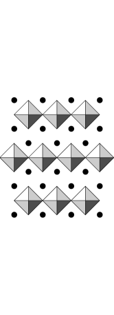
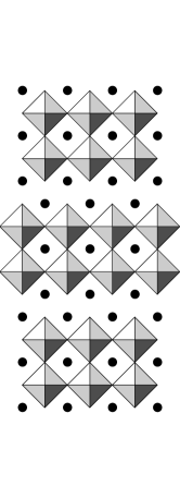
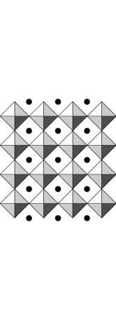
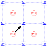
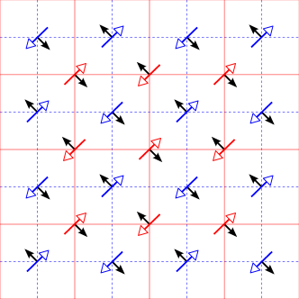
Cation stoichiometry has a large impact on the physics of these materials, but is difficultYamamichi et al. (1994); Taylor et al. (2003) to control during film growth. Cation non-stoichiometries in the perovskites can potentially take the form of point or planar defects, with perovskites experimentally found to resist point defect formation upon sufficient cation non-stoichiometryBalachandran and Eror (1982); Smyth (1985); Witek et al. (1984). In A2+B4+O materials (such as SrTiO3) with an excess of species A (or, more precisely, additional AO to maintain charge neutrality), the resulting planar defects produce a series of homologous compounds of the form An+1BnO3n+1. (Note that bulk ABO3 corresponds to one end member of this series, , and bulk AO corresponds to the other end member, .) The An+1BnO3n+1 compounds, known as the Ruddlesden–Popper (RP) phasesRuddlesden and Popper (1957, 1958), reflect the modification of the cation stoichiometry by the addition of an extra unit of AO per units of bulk ABO3 material. Structurally, they take the form of bulk ABO3, separated every layers by the insertion of excess planes of AO to create stacking faults of the form /AO/BO2/AO/AO/BO2/AO/ in the normal /AO/BO2/AO/BO2/AO stacking sequence of the material. Across each such stacking fault, the bulk perovskite slabs are alternately displaced by in-plane vectors of the form . Figure 1 depicts four members of the homologous series An+1BnO3n+1, with , , , and .
RP phases, specifically, manifest additional properties beyond those of bulk perovskites; these include high dielectricityKwestroo and Paping (1959); Haeni et al. (2001), thermoelectricityLee et al. (2007), photocatalysisLiang et al. (2008), unconventional superconductivityMaeno et al. (1994), quantum criticalityGrigera et al. (2001), metamagnetismPerry et al. (2001), ferromagnetismCao et al. (1997), colossal magnetoresistanceMoritomo et al. (1996), and x-ray optic adaptabilityMeyer et al. (2006). Despite the interest in such compounds, experimentalists have faced difficulties growing RP phases for “intermediate” values of ()Schlom et al. (1990); Klausmeier-Brown et al. (1992); Peña et al. (1994); Bader et al. (1998). For example, strontium titanate (SrTiO3) compounds with such stoichiometries tend not to form growths of a single uniform RP phase, but rather materials with multiple regions, each with RP phases of different values of , so-called “intergrowths.”Tilley (1977); Ramesh et al. (1990); Schilling et al. (1993) Indeed, conventional ceramic powder sintering has only produced single-phase RP samples for : Sr2TiO4, Sr3Ti2O7, and Sr4Ti3O10Tilley (1977); McCarthy et al. (1969a). More recently, successful creation of intermediate members of the Srn+1TinO3n+1 series has been accomplished with advanced techniques for epitaxial growth of thin-films under thermodynamical non-equilibrium conditions, such as sputteringTaylor et al. (2003), pulsed laser deposition (PLD)Iwazaki et al. (1999, 2000); Shibuya et al. (2008), and molecular beam epitaxy (MBE)Haeni et al. (2001); Tanaka and Kawai (2000); Tian et al. (2001); Fisher et al. (2007), with characterization by high-resolution transmission electron microscopy (HRTEM)Tian et al. (2001) and x-ray diffraction (XRD)Suzuki et al. (2000). Such recent observations renew the urgency for a careful theoretical study of RP phases with intermediate and large values of .
Previous theoretical work on RP phases of perovskites includes a limited number of both ab initio electronic structure calculations and empirical potential studies. A pioneering empirical-potential studyUdayakumar and Cormack (1988) in the 1980’s considered all values of for strontium titanate but did not report sufficient precision to resolve differences among any of the phases above . A decade later, a subsequent empirical-potential studyMcCoy et al. (1997) was able to resolve differences among phases but only considered phases for . Total energy electronic structure studies have also been carried out, primarily for strontium titanateFennie and Rabe (2003); Suzuki and Fujimoto (2001); Le Bacq et al. (2006); Noguera (2000); Weng et al. (2006); Reshak et al. (2008); Music and Schneider (2008) () but also for three additional perovskite transition-metal oxidesWeng et al. (2006) ( only). None of these studies have explored the significant interactions which we find to exist between the rotational states of the oxygen octahedra on opposite sides of the AO/AO stacking faults.
Many perovskites that form RP phases exhibit antiferrodistortive (AFD) behavior in which the oxygen octahedra tend to rotate in an alternating spatial pattern from their ideal orientations with a relatively low energy scale, so that numerous structural phases exist for the corresponding bulk materials. Unless a full quantum statistical treatment of the RP phases is considered in the theoretical calculations, the bulk regions in these phases will tend to relax to the zero-temperature ground state within the model used to describe the material. One must therefore carefully and explicitly consider two interrelated effects: (a) the interaction between different possible antiferrodistortive reconstructions on either side of the stacking faults and (b) the possibility that these reconstructions will assume different orientations and thus prefer lattice structures in potential conflict across the stacking fault. If the different possible reconstructions of octahedral rotations are not considered, the true ground state of the RP phases may be missed. If the lattice vectors are not allowed to relax fully, the extraction of the formation energy of the RP phases will suffer errors which scale with the size of the bulk regions (i.e., linearly with ), as we demonstrate below in Section V.1. The aforementioned theoretical works thus have limited applicability, even for the small values of which they consider.
Indeed, experiments reveal that these effects are known to be present in RP phases of perovskites; for example, both Srn+1TinO3n+1 and Can+1TinO3n+1 exhibit rotations of their oxygen octahedra, for and RP phasesElcombe et al. (1991). Previous work has considered general group-theoretical studies of the space groups of possible octahedral rotation patterns in RP phasesAleksandrov and Bartolome (1994); Hatch et al. (1989), but with restrictions either to the RP phase or to a limited number of possible relative rotational orientations on opposite sides of the stacking faults.
In this work, we provide a careful, comprehensive atomistic study of the Ruddlesden–Popper phases of a physical model of an antiferrodistortive perovskite, considering a wide range of (specifically, ), properly accounting for the full lattice relaxation of the RP phases, and exploring all combinatorial possibilities of different orientations of oxygen octahedra on opposite sides of the AO/AO stacking faults. In Section II, we introduce the class of materials which we consider, those antiferrodistortive perovskites which form intrinsic RP phases and belong to the Glazer system of the greatest symmetry commonly found in nature: Glazer (1972). Section III then presents an exhaustive catalogue of the different possible structures for RP phases in perovskites within this system. In generating this catalogue, we introduce a convenient symmetry algebra which allows one to quickly enumerate the structures, and we use it to find a total of five symmetry-distinct possibilities (consistent with distorted phases Nos. – which Hatch et al.Hatch et al. (1989) found for the RP phase after extensive searching with a computer program). Section IV then introduces the shell-potential model and the numerical techniques which we use.
Section V.1 explores the aforementioned five distinct configurations for all RP phases for . We find that the energies of RP phases are indeed quite sensitive to octahedral rotations, sufficiently sensitive that unfavorable configurations become unstable relative to phase separation into bulk perovskite and bulk A-oxide. In fact, the effect is sufficiently strong to suggest some intriguing possibilities. For low densities of stacking faults (high ), the rotational states of the octahedra neighboring the faults might be constrained, even at temperatures where the octahedra in the bulk librate freely, so that different degrees of order are observed in the bulk and at the interfaces. For high densities of stacking faults (low ), this effect may increase the transition temperatures associated with the octahedral rotations.
Section V.2 considers interactions between the stacking faults present in the RP phases. For each configuration, we examine the energy of the An+1BnO3n+1 RP phases as a function of , which directly measures the separation between stacking faults. We demonstrate that the interaction is quite sensitive to the octahedral rotations, differing in strength by as much as a factor of two depending on the rotations. Next, Section V.3 examines the issue of the asymptotic form of this interaction for . We find that the interaction between stacking faults varies as the inverse of the distance between them, and we extract both the binding energies of stacking faults and the formation energies of isolated faults. Again, we find that the interaction energy between faults is highly sensitive to the different possible rotational states of the oxygen octahedra and may even lead to ordering at the stacking faults at temperatures where the bulk regions have lost their orientational order. This section then concludes with a proposal for a simple physical mechanism to explain the strong dependence of the interfacial energy on the rotational state of the octahedra: some configurations result in movement of like-charged neighboring oxygen ions directly toward each other and thus are high in energy, whereas others result in movement of oxygen ions past each other and thus are low in energy.
Finally, in Section V.4, exerting care in tracking the chemical potentials of the various reference systems, we verify that the formation of isolated planar stacking faults is favored over the formation of point defects in our model material, regardless of the rotational state of the oxygen octahedra.
II Background
In this work, we embark on a study of the generic effects of octahedral rotations on RP phases. For this first such study, we shall focus on the most highly symmetric of the twenty-three possible Glazer systemsGlazer (1972). There are two such systems, denoted in Glazer notation as and , only the latter of which is commonly found in nature. Examples of perovskites include LaAlO3Glazer (1972), NdAlO3Geller and Bala (1956); Harley et al. (1973), CeAlO3Harley et al. (1973), BiFeO3Moreau et al. (1970), LiNbO3Moreau et al. (1970), LiTaO3Moreau et al. (1970), PbZr0.9Ti0.1O3 (PZT)Glazer (1975), and many others catalogued by GlazerGlazer (1972) and Megaw and DarlingtonMegaw and Darlington (1975).
The Glazer notation refers to the relative state of rotation of neighboring oxygen octahedra in antiferrodistortive reconstructions of the perovskite structure. In actual fact, the motion of the octahedra within such reconstructions is only approximately a rotation as the oxygen atoms are confined to the faces of each cube; regardless, we shall refer to their motion as rotational throughout. Glazer exhaustively catalogued all twenty-three possible patterns of these octahedral rotations (“tilts” in his terminology)Glazer (1972, 1975), with each category assigned an appropriate nomenclature to denote the axis of rotation and the relative sign of successive rotations along that axis. In brief, in the system, all oxygen octahedra rotate either clockwise or counterclockwise about a fixed trigonal axis in an alternating checkerboard pattern in all three dimensions, resulting in a cell-doubling reconstruction with a supercell. (Greater details appear in Section III.)
The antiferrodistortive phase transition, associated with these rotations, occurs due to the softening of the optical phonons at the corner ( zone boundary) of the Brillouin zone, as famously studied experimentallyUnoki and Sakudo (1967); Fleury et al. (1968); Shirane and Yamada (1969) and theoreticallyPytte and Feder (1969); Feder and Pytte (1970) and reviewed extensivelyScott (1974). The transition is therefore also sometimes known as a Zone Boundary Transition (ZBT) and was recognized even earlier as a means by which crystals could double the size of their primitive cellsCochran (1961). The rotation of the oxygen octahedra accompany the softening of these phonons, with their rotation angles serving as the order parametersMüller et al. (1968). The degeneracy of this phonon mode in the higher-temperature cubic phase enables the rotation of octahedra about different axes — , , and — to break the crystal’s symmetry below its critical temperature. While the system results from rotations about the axis, all three systems emerge from the same underlying instabilityScott (1974); Axe et al. (1969), with anharmonic interactions determining the resulting low-temperature lattice symmetryThomas and Müller (1968). As the underlying physics is so similar, we thus expect that perovskites in Glazer systems other than will exhibit similar generic behaviors to the results expounded below.
In seeking a model potential for our study, we searched the literature for shell-potential parameters among the perovskites. Unfortunately, we discovered that the ground states of the available models generally do not correctly match their corresponding Glazer systems.Lee (2008) We were only able to identify a single material, lanthanum aluminate (La3+Al3+O), with a ground state in the correct Glazer system.Lee (2008) Unfortunately, lanthanum aluminate does not form intrinsic RP phases, since its composition as An+1BnO3n+1 would violate basic charge balance; intrinsic RP formation requires perovskites with an A2+B4+O chemical formula for the additional A2+O2- layer to be neutral. Lanthanum aluminate, however, can form extrinsic RP phases by incorporation of additional neutral layers of another perovskite, strontium oxide: SrOLanAlnO3n.
For simplicity of this initial theoretical study, we focus on perovskites that form intrinsic RP phases, examples of which from the system do indeed exist in nature (e.g., BaTbO3Glazer (1972)). However, we are not aware of shell potentials for any of these materials. On the other hand, we discovered that the shell-potential model commonly used for strontium titanate (Sr2+Ti4+O), which forms intrinsic RP phases, does possess a ground state of the type.
Indeed, on a microscopic level, strontium titanate is very similar to lanthanum aluminate. In fact, early x-ray experimentsLytle (1964a, b) erroneously predicted a low-temperature ( K) phase transition in strontium titanate to a rhombohedral lattice (generally associated with microscopic ordering), only to be corrected by subsequent spectroscopic studiesAlefeld (1969); Unoki and Sakudo (1967). Strontium titanate assumes its actual tetragonal ground-state structure through a famous cell-doubling antiferrodistortive phase transition near Kvon Waldkirch et al. (1973), whose “physical origin is the same”Müller et al. (1968) as that of lanthanum aluminate. Indeed, this transition is “strikingly analogous in all respects”Scott (1969, 1970) to that of lanthanum aluminate, although the energy scales are quite different. (The structural phase transition temperature for lanthanum aluminate is KMüller et al. (1968); Howard et al. (2000).) Further connections between these two perovskites are enabled by the classical concept of the Goldschmidt tolerance factorGoldschmidt (1926), , a normalized ratio of the radii of ABO3 ions historically used to categorize perovskites and predict their ground statesGalasso (1969). In fact, lanthanum aluminate has a tolerance factor within % of that of strontium titanate (data compiled by ShannonShannon (1976)).
In sum, the parameters for the shell potential commonly used for strontium titanate describe a perovskite which intrinsically forms RP phases within the desired Glazer system. It is not surprising, then, to discover empirical evidence for perovskites, such as lanthanum aluminate, which closely resemble strontium titanate but with octahedral rotations. The standard shell potential for strontium titanate can thus reasonably be utilized as a parameterization for generic perovskites which form RP phases. Therefore, in interpreting our results, one should be mindful that details, such as the values which we find for the various quantities, may not apply to any specific perovskite. However, the general phenomena that we uncover, such as the enumeration of possible octahedral configurations and the general form and scale of the various interactions, may be taken as representative of the class of perovskites in RP phases. Moreover, since the underlying physical mechanism is the same for other Glazer systems, many of the phenomena which we uncover should be considered for the RP phases of all AFD perovskites.
III Classification of octahedral rotations in RP phases
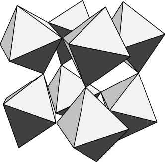
We return now to a careful examination of the specifics of the Glazer reconstruction, as visualized in Figure 2. The oxygen octahedra each rotate around one of the eight possible axes (expressed in the coordinates of the closely related cubic structure), with neighboring octahedra rotating in opposite directions in a cell-doubling, alternating three-dimensional checkerboard pattern. The crystal itself responds to the presence of these trigonal rotations about a common axis by stretching or compressing along that axis, forming a rhombohedral Bravais lattice. Selection of a specific oxygen octahedron as reference then permits eight possible distinct bulk configurations, each characterized and enumerated by the particular choice of one of the eight possible trigonal rotation axes for that specific octahedron. These eight reconstructions can be characterized either as , namely a selection of an overall sign and a choice of one of the four unsigned rotation axes, or, alternatively, simply as one of eight signed axes.
The former perspective is visualized in Figure 3. The four (unsigned) rotation axes designate the reconstruction at an arbitrary origin of the crystal, where a final choice of sign determines whether the rotation at the origin is either clockwise (“positive”) or counterclockwise (“negative”), thereby fully specifying the microscopic state of the crystal. Note that a change in this sign choice corresponds precisely to a rigid translation of the crystal by a primitive translation vector (to a position in the crystal with opposite sign of rotation, due to the checkerboard pattern of the reconstruction). Such a translation would not be observable on a macroscopic level.

III.1 Isolated stacking faults
The RP phases observed in experimentsTilley (1977); McCarthy et al. (1969a, b) consist of superlattices of bulk perovskite slabs separated by the insertion of excess AO planes to create stacking faults of the form /AO/BO2/AO/AO/BO2/AO/ in the normal /AO/BO2/AO/BO2/AO/ stacking sequence. Across each such stacking fault, the bulk perovskite slabs are alternately displaced by in-plane vectors of the form . To our knowledge, however, no one has yet explored the effects of different combinations of possible symmetry-related bulk reconstructions on opposite sides of the repeated AO planes.
To enumerate the distinct possible configurations for such stacking faults, we restrict our consideration to cases where the material on either side of the stacking fault possesses a specific bulk reconstruction throughout. We first focus on the reconstruction of the bulk material on the side “below” (at lower values for ) the AO/AO stacking fault, which we shall denote as side . As discussed above, the microscopic configuration of bulk material on side can be fully specified by noting the rotation axis of the octahedron at an arbitrary, but from then onward fixed, origin . The rotation axis of this particular reference oxygen octahedron can then assume any of eight choices among the axes, which we can regard as a selection of an overall sign (“positive” or “negative”) and a choice of one of the four (unsigned) rotation axes. This specification then determines the entire microscopic structure of the bulk material in side , according to the three-dimensional checkerboard pattern of alternating signs for the rotation axes. For the present purpose, we choose always to select the reference octahedron from among those octahedra immediately neighboring the stacking fault which have a positive rotation in the above sense of the choice of overall sign.
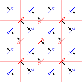
Next, as noted above, the bulk perovskite on the other side, , of the stacking fault is displaced, in general, by a vector relative to side . Temporarily disregarding the rotational state of all octahedra, we note that all four of these displacements are equivalent, since the octahedra on are positioned at the centers of squares formed by the octahedra on . (See Figure 4.) This equivalence (apart from rotational states of the octahedra) allows us to choose a standardized displacement from to select the origin . (More specifically, , where represents the vertical displacement between octahedra on opposite sides of the stacking fault, and is a unit vector in the direction.)
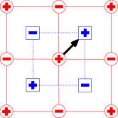
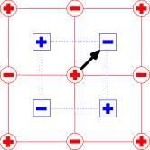
The rotation state of then completely specifies the entire microscopic structure of the bulk material in side . This rotation state can be specified as a selection of an overall sign (“positive” or “negative”) and a choice of one of the four (unsigned) rotation axes. Figure 4 illustrates exactly these two possible choices of sign, where the reference octahedron on side is either positive (Figure 4(a)) or negative (Figure 4(b)). Generically below, we shall refer to these two possible sign patterns in the stacking-fault configuration as “” and “”, respectively, reflecting the overall sign of the rotation of . The combination of these two sign patterns and the four possible unsigned rotation axes (not indicated in Figure 4) for each origin, and , leads to a total of distinct possible configurations for this stacking fault.
Next, we consider equivalence of stacking faults under application of symmetry. As discussed above, the rotation axis of can always be selected to be among the four (unsigned) axes. Because symmetries interconvert all four of these axes (, , ), an overall rotation of the coordinate system can be found to make the rotation about the axis. We may thus define the rotation axis of to always be the (unsigned) axis. This then narrows the phase space of thirty-two configurations listed above to now only distinct configurations.
These eight distinct configurations can be enumerated using two related nomenclatures (seen in Table 1), one which is algebraically explicit and suitable for symmetry arguments and the other which is more compact and convenient for communication. In the former case of the algebraic specifier, we enumerate each configuration by specification of the rotation states of each reference octahedron, and , expressing the rotation states in terms of (signed) vectors. For example, if is in rotation state and is in rotation state , we write . For a more compact notation, we can take, without loss of generality as shown above, the rotation state of to always be . The unsigned rotation axis of is then related to that of by one of the four rotations of angles {, , , }. To denote the configuration of the stacking fault, we then append the remaining choice of sign for to its rotation angle to produce a compound rotation-sign specifier. For example, the configuration from the preceding example may be more compactly written as (since ). Finally, Table 1 enumerates all eight configurations according to both their rotation-sign and algebraic specifiers.
| Rotation-sign Specifier | Algebraic Specifier |
|---|---|
The above enumerated eight stacking-fault configurations can be reduced yet further by considering the effects of additional, more subtle, symmetry operations — specifically, the , , and rotations and inversion . To demonstrate the effects of such symmetry operations, we first consider two of the above eight stacking-fault configurations, in Figure 5(a) and in Figure 5(b). From the figure, these two configurations clearly differ only in the overall choice of sign pattern for the upper layer (’s). We now use symmetry arguments to demonstrate that these two stacking-fault configurations are actually equivalent, related simply by a rotation.
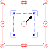
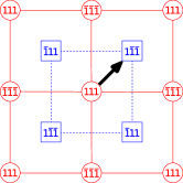
The general strategy which we shall employ is to exploit the fact that the algebraic specifier not only determines the rotation state of all of the octahedra in the crystal but also transforms in relatively simple ways under the application of symmetry operations to the overall crystal. Figure 5(c) illustrates the state of the crystal in Figure 5(a) after the application of a symmetry about a specific axis. To ensure that the basic crystalline structure maps back onto itself, this axis is chosen to pass at equal distances to the two neighboring AO layers in the stacking fault and through the point immediately above the reference octahedron (base of the standardized displacement in Figure 5(a)). The application of effects the following changes to the configuration in Figure 5(a):
- 1.
-
2.
the rotation state of maps from to ;
- 3.
-
4.
the rotation state of this latter octahedron maps from to .
To determine the algebraic specifier for the final configuration in Figure 5(c), we now identify an octahedron on the lower side of the stacking fault which has a positive rotation from among the (unsigned) axes (base of the standardized displacement in Figure 5(c)). The rotation state of this octahedron, combined with that of the corresponding reference octahedron on the upper side, defines the algebraic specifier for the resulting stacking fault. For this particular case, it is evident from the figure that . Reference to Table 1 then identifies , so that , as direct comparison of Figures 5(b) and (c) confirms. Thus, we conclude that and are identical and related by the rotation.
To develop an algebra for the action of symmetry operations on arbitrary stacking-fault configurations, we consider the effects of such operations on general stacking-fault configurations, . For the case of , we note in preparation that the action of on any vector is . Then, as above, the operation of transforms the generic algebraic specifier as follows:
-
1.
it swaps and ;
-
2.
it maps to ;
-
3.
it changes the sign of ;
-
4.
it maps to
In short,
Table 2 summarizes the effects, similarly determined, on stacking-fault configurations of a number of useful symmetry operations: rotations , , , and and inversion . (Note that inversion, through the midpoint of the vector connecting the two reference octahedra and , requires special care: it does not change the direction of pseudo-vectors such as the rotation axes of the different octahedra but simply interchanges the two sides, and .)
| Symmetry | Algebraic Specifier | |
|---|---|---|
| Original | Final | |
We are now able to demonstrate further symmetry reduction of the stacking-fault configurations. Table 1 lists all eight possible stacking fault configurations, providing both rotation-sign and algebraic specifiers for each. Application of the symmetry operations from Table 2 to these configurations, and subsequent translation by if necessary to make of rotation state , generates the following relationships,
| (1a) | ||||
| (1b) | ||||
| (1c) | ||||
The above symmetry operations, which each involve interchange of the and sides of the interface, demonstrate equivalence among the set of four stacking faults, {, , , }. Thus, only five unique stacking-fault configurations remain, , , , , and . Comparison of the algebraic specifiers of these five configurations, from Table 1 above, with the computer-generated distorted phases listed as Nos. –, in Table III of Hatch et al.Hatch et al. (1989), confirms that our result is consistent with theirs, though theirs is limited to the RP phase. We confine ourselves to discussion of these five unique configurations for remainder of this work.
III.2 RP phases
The RP phases, which we study in this work, consist of periodic arrays of the above configurations of stacking faults. While constructing such arrays from individual stacking faults, the array periodicity may be maintained either through simple alternating patterns of bulk regions ( sequencing) or through more complex, and possibly lower-energy, patterns (for example, sequencing).
Immediately below, we demonstrate that, in fact, an sequence of bulk regions always corresponds to repetition of the same type of stacking-fault configuration. Three very compelling reasons then follow for studying RP phases with this type of periodicity. First, one should expect the preferred RP phase to consist of a sequence of stacking faults, which are all of the lowest-energy configuration; this would then naturally correspond to an sequence. Second, actual experiments find superlattice sizes consistent with small, simple repeat unitsTilley (1977); McCarthy et al. (1969a, b). Finally, isolated stacking faults are also observed under certain conditionsTilley (1977), and the study of RP phases of periodicity, containing two identical faults in each primitive unit cell, then allows for the extraction of the behavior of individual isolated faults.
To establish that an sequence of bulk regions corresponds to repetition of the same configuration of stacking fault, we must prove the equivalence of the two stacking faults, and , in such an RP phase. As in Section III.1, we take the algebraic specifier for this first stacking fault to be the generic where and refer to the rotation states of the two reference octahedra for this fault, and respectively. We must then choose two corresponding reference octahedra and for the second stacking fault . Since , we can set and , where is the number of the RP phase (An+1BnO3n+1) so that layers of material separate from and similarly separate from . (Consideration of the case should make this apparent.) The alternating octahedral rotations of this Glazer system thereby define the algebraic specifier for the stacking fault as . However, displacement of the arbitrary origin (reference octahedra) by , for cases when is even, generates an equivalent algebraic specifier for this interface which is now insensitive to , . Finally, we apply inversion symmetry, as introduced in Table 2, to this stacking fault, , and thus prove that the stacking fault is equivalent to the fault.
Lastly, since all stacking faults in an RP phase always possess equivalent configurations, we can uniquely label these RP phases using the same rotation-sign specifiers established above for the five symmetry-distinct stacking faults: , , , , and .
IV Model and computational methods
IV.1 Shell potential
As discussed in Section II above, to study the generic behavior of perovskites which form RP phases, we employ a shell-potential modelDick and Overhauser (1958) parameterized for strontium titanateAkhtar et al. (1995). Shell-potential models are formulated as an extension to ionic pair potentials and employed to capture the polarizability of the atomic constituents. The shell model separates each ion into two parts, a core and an outer shell, which possess individual charges that sum to the nominal charge of the ion. The total model potential consists of three terms,
| (2) |
representing, respectively, the polarizability of the ions, and the Coulomb and short-range interactions among the ions. The polarizability is captured by harmonic springs connecting the core and shell of each ion, so that has the form,
| (3) |
where is the core-shell separation for ion and the are a set of ion-specific spring constants. The Coulomb contributions take the form,
| (4) |
where and range over all cores and shells (excluding terms where and refer to the same ion), and are the corresponding charges, is the distance between the charge centers, and is Coulomb’s constant. Finally, the short-range interactions are included through a sum of BuckinghamBuckingham (1958) pair potentials (which can be viewed as combinations of Born-MayerBorn and Mayer (1932) and Lennard-JonesLennard-Jones (1931) potentials) of the form,
| (5) |
where and range over all shells and , , and are pair-specific adjustable parameters. Here, the first term (Born-Mayer) serves as a repulsive short-range interaction to respect the Pauli exclusion principle, and the second term (Lennard-Jones) models the dispersion or van der Waals interactionsvan der Waals (1873). The specific electrostatic and short-range shell-model parameters used in this study were fit to strontium titanate by Akhtar et al.Akhtar et al. (1995), with values as listed in Tables 3 and 4. Finally, we wish to emphasize again, as it is rarely mentioned explicitly in the shell-potential literature, that the pair-potential terms in apply to the shells only, and not to the cores.
Shell models have been extensively used for decades as the primary empirical potential for modeling perovskites and other oxidesLewis and Catlow (1985); Catlow and Stoneham (1983). We tested the correctness of our coded implementation of this potential through comparisons of lattice constants and elastic moduli without the AFD reconstruction and find excellent agreement. For instance, using the same shell potential and the same non-reconstructed ground state, we predict a volume per SrTiO3 chemical unit of Å3, which is within % of the value calculated by Akhtar et al.Akhtar et al. (1995) For the elastic moduli, we find GPa, GPa, and GPa, which are within %, %, and %, respectively, of the values from Akhtar et al.Akhtar et al. (1995) From this, we conclude that our implementation of the potential is correct. We also would like to note that, when the reconstruction is considered, significant changes occur, and we find, instead, a volume per SrTiO3 chemical unit of Å3 and elastic moduli of GPa, GPa, and GPa. This underscores the importance of considering AFD reconstructions when constructing such potentials.
| Ion | Shell | Core | Spring Constant |
|---|---|---|---|
| Charge [e] | Charge [e] | [eVÅ-2] | |
| Sr2+ | |||
| Ti4+ | |||
| O2- |
| Interaction | A [eV] | [Å] | C [eVÅ6] |
|---|---|---|---|
| Sr2+ O2- | |||
| Ti4+ O2- | |||
| O2- O2- |
IV.2 Numerical methods
In this work, we compute the Coulombic interactionEwald (1921) from (4) using a Particle Mesh Ewald algorithmDarden et al. (1993); Essmann et al. (1995); Deserno and Holm (1998) with all real-space pair-potential terms computed out to a fixed cutoff distance using neighbor tables. Analytic derivatives are used to determine the forces on the cores and shells within the supercell, and finite differences are used to compute the generalized forces on the superlattice vectors. While such finite-difference methods occasionally introduce issues with numerical precision into the resulting calculations, we are able to mitigate such effects with care in selection of the finite-difference step, scaling it proportionally to the sizes of the lattice vectors involved.
With the gradients determined as above, we relax each system using the technique of preconditioned conjugate gradient minimizationHestenes and Stiefel (1952) (specifically, the Polak-RibièrePolak and Ribière (1969) method), fully optimizing the ionic coordinates in an inner loop of the routine and then optimizing the lattice vectors in an outer loop. The preconditioner applies only to the ionic relaxation of this procedure and scales the generalized force on the geometric center of each ion (mean position of the core and shell) separately from the generalized force on the core-shell displacement, with the latter scaled in inverse proportion to the spring constant of the corresponding ion. This process ensures that all supercell energies are relaxed with respect to both ionic and lattice coordinates to a precision of µeV per supercell.
IV.3 Ground state
To establish the ground state of the model potential used in our calculations, we have carried out what we regard as a thorough, but not exhaustive, search for a probable ground-state structure. Indeed, we have found no alternative structure which relaxes to an energy less than our candidate ground-state structure within our potential. We performed quenches on hundreds of random displacements from the idealized positions of the primitive unit cell to explore various potential reconstructions for supercells up to . We also considered a number of highly ordered configurations commensurate with antiferrodistortive disordering.
Among those minima which we explored, we selected the lowest-energy configuration to serve as the bulk crystalline state throughout this study. This configuration possesses a fairly regular pattern as depicted in Figure 2, namely each oxygen octahedron rotates slightly along trigonal directions in a cell-doubling, alternating three-dimensional checkerboard pattern, which is precisely the desired Glazer system from Section II. We also find that the lattice vectors assume the rhombohedral symmetry commonly found in perovskites, with the cubic lattice stretching along the same trigonal axes about which the octahedra rotate.
The specific lattice vectors which we find for the reconstructed supercell of our model are the columns of the following matrix,
IV.4 Construction of RP supercells
Our construction of initial ionic configurations for the An+1BnO3n+1 RP phases proceeds through a detailed process defined in Section III. As discussed there, we carefully consider a large number of combinatorial possibilities resulting from the different geometries due to the aforementioned cell-doubling, bulk reconstruction. We construct each configuration of the RP phase by stacking layers of bulk perovskite along the direction, with the two stacking faults (excess AO planes) so situated as to equally divide the supercell into two bulk slabs, each with layers and potentially different reconstructions. Relative to each other, these bulk slabs are also laterally displaced by one of the four (equivalent) vectors at each stacking fault. We perform this procedure to create all eight configurations from Section III.1, through combinations of reconstructions in the two bulk slabs, for RP phases from , containing from to ions, respectively. Each RP superlattice system is then fully relaxed, as described above, both in terms of internal ionic coordinates and lattice vectors, until the energy is minimized to within a precision of µeV. In all cases, we find that the material on either side of the stacking fault maintains a uniform bulk reconstruction throughout, so that the enumeration of Section III.1 is suitably complete. Finally, we test for meta-stability by creating ensembles of – samples for each configuration of octahedra rotations for all RP phases up to , introducing root-mean-square displacements of Å for each coordinate axis of every core and shell, and quenching each of these randomized systems.
V Results
As described in Section II above, the results obtained below have been computed with the standard shell-potential model for strontium titanateAkhtar et al. (1995); Lewis and Catlow (1985); Catlow and Stoneham (1983), but are interpreted to represent the generic behavior of an antiferrodistortive perovskite (ABO3) from among the class of perovskites within the Glazer system which form RP phases.
V.1 Formation of RP phases
After constructing the various possible RP phases according to the prescription in Section IV.4, the ideal procedure for determining the energetics of the RP phases is to fully relax each system, in terms of both internal atomic coordinates and superlattice vectors, without any externally imposed symmetries. The energies of the reference bulk materials, perovskite (ABO3) and A-oxide (AO), should also be fully relaxed in the same sense.
Without full relaxation of lattice vectors for both the RP phases and bulk reference cells, any attempts to extract energies will introduce significant errors that scale in proportion to the amount of bulk material between stacking faults. (Such failures to fully relax the lattice vectors might arise due to expediency in ab initio studies or through attempts to simulate higher-temperature phases by imposing a higher-temperature lattice structure while relaxing ionic coordinates.)
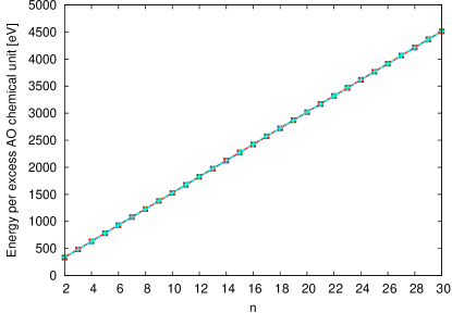
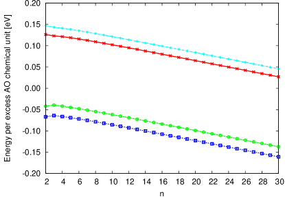
Figure 6(a) shows actual results obtained from such a methodologically flawed procedure, where the energy needed to form the RP phase from the bulk perovskite ABO3 and bulk A-oxide AO, , is computed without full relaxation of the lattice vectors of the RP phase, but instead with the enforcement of tetragonal lattice vectors associated with a higher-temperature symmetry not possessed by the ground state of our model. Under these constraints, the energy exhibits a clear linear increase with , the amount of bulk material between stacking faults, due to an inflated RP-phase energy associated with artificial strain in the bulk regions. (Note that the results in the figure are visually indistinguishable whether or not one allows the perovskite or A-oxide bulk reference cells to fully relax.) Figure 6(b) shows results obtained where the lattice vectors of the RP phases are allowed to relax fully but the lattice vectors of the bulk reference cells are not. In this case, excess bulk energy is not included in the RP cell but instead in the bulk reference cells, and the energy of formation now decreases linearly with . Either type of error will confound the extraction of meaningful information on the RP phases. The calculation of such phases is herein seen to be quite delicate, a fact which only becomes obvious when calculations are pursued for large values of .
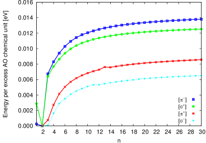
Figure 7 presents the results, properly calculated with full relaxation of all lattice vectors, for the energies of all eight stacking-fault configurations of our model potential, relative to the corresponding amounts of the fully relaxed, reconstructed perovskite and the fully relaxed A-oxide material. As in the examples above, the energies are expressed per excess AO chemical unit, of which appear in each reconstructed RP superlattice unit cell (and of which appear in each supercell with two stacking faults and thus two RP superlattice unit cells). The final relaxed RP configurations indeed are not distinct, as expected from the symmetry arguments in Section III.1, which showed that , so that there should be at most five different configurations. Somewhat unexpectedly, rather than displaying five separate curves for the five symmetry-distinct configurations (, , , , ), Figure 7 instead shows only four curves: we find that the configuration is unstable and relaxes directly to the configuration, as determined by energy calculations and observations of transitions in lattice symmetries for each configuration during full relaxation. Additionally, the configuration appears meta-stable, often transitioning, upon small perturbations described in Section IV.4, to the configuration. The remainder of this discussion thus only reports on the behavior of the final three distinct, stable configurations (, , ) as well as the one additional distinct, meta-stable configuration ().
From Figure 7, we note immediately that, depending upon the relative rotational orientation of oxygen octahedra on either side of the stacking faults, the configurations separate into two groupings, one with positive energy and one with negative energy relative to phase separation into bulk perovskite and bulk A-oxide. The energy scales associated with the different configurations may thus be sufficient to either stabilize or destabilize the formation of an RP phase.
Moreover, for our model potential, the two more stable stacking-fault configurations ( and ) possess negative energies for all , providing the first demonstration that RP phases can be favored over formation of bulk perovskite and A-oxide for all values of . Also, we find the configuration to be favored over all other possible configurations in our model, regardless of the value of .
It is also immediately apparent that the RP phases for deserve special consideration for our model potential. The phases for the two configurations with positive energy collapse to related configurations with negative energy, with becoming and becoming . This might be related to the realization that the full reconstruction cannot be expressed on either side of the stacking fault for an RP phase, and thus these higher-energy configurations forfeit some stability for the RP phase.
The magnitude of the energy differences between configurations is not only sufficient to affect the stability of the phases, but is also significant compared to thermal energy scales. For instance, we find the separation between the stable and unstable groupings to be meV per excess AO chemical unit (or meV per RP superlattice unit cell, An+1BnO3n+1). To place this energy in context, we can also consider the energy per interfacial oxygen octahedron (one on the top and bottom of the stacking fault for each excess AO chemical unit), meV, which is about meV per configurational (rotational) degree of freedom. This is larger than, but comparable to, the thermal energy at room temperature, meV, so that at significant temperatures we still can expect a small, but statistically noticeable, tendency for the stacking fault to preferentially select the minimal energy configuration over other disfavored configurations.
This energy scale is also significantly larger than the energy scales we might expect for excitations in the bulk of the material. For instance, the structural phase transition in strontium titanate (the material to which the original model actually had been fitAkhtar et al. (1995)) occurs near Kvon Waldkirch et al. (1973), which corresponds to an energy scale of meV. To further place the above meV interfacial energy scale in context, we consider the energies within our model of two alternate rotational bulk reconstructions, those with rotations about axes (orthorhombic) and axes (tetragonal), finding rotational energy scales of meV and meV, respectively, relative to the ground-state reconstruction. These comparisons lead to the intriguing conjecture that, for some perovskites with low densities of stacking faults (high ), there exist a range of temperatures above the bulk structural phase transitions, in which the bulk rotational energy scale is insufficient to constrain the rotations of the octahedra, while the interfacial energy scale is suitable to constrain the octahedral rotations to specific preferred orientations. This corresponds to a picture of “fuzzy” octahedra in the bulk regions with noticeable orientational preferences remaining for the octahedra at the stacking faults. Alternatively, for perovskites in RP phases with low values of and higher densities of stacking faults, one might expect this increased energy scale to raise the transition temperature associated with octahedral rotations.
V.2 Stacking fault interactions and
intergrowth formation
While Section V.1 discussed the relationship among energies of formation of different configurations, it is further instructive to examine the energy and behavior of each configuration independently, as a function of separation between stacking faults. Figure 8 plots the interaction energies per excess AO chemical unit for each configuration, which, for a given configuration, are the formation energies of each phase relative to the energy of its phase. (For the two stable, low-energy configurations within our model, the phase is, in fact, lowest in energy, so that this plot represents the binding energies of the stacking faults for these configurations. For the two high-energy configurations, unstable to dissociation into separate regimes of bulk perovskite and A-oxide, the phase is actually lowest in energy, so that this plot approximately represents the binding energies of the stacking faults.) For our model, in all cases, there is a relatively weak, but consistently attractive, interaction (apart from special cases for ), varying by over a factor of two from – meV per excess AO chemical unit, depending upon the stacking-fault configuration. The strengths of the interaction occur in precisely the same sequence as the stability of the configurations, with the more attractive interactions occurring in the more stable configurations.
Within the current model, the universally attractive and eventually asymptotic nature of the interaction for leads to a set of interaction energies with downward curvature. The standard secant construction for mixed phases then indicates that, for , the energy of a system can always be lowered by forming a so-called “intergrowth” phase, mixing regions of lower- and higher- phases (i.e., non-uniformly changing the separation between stacking faults that define the phases) while maintaining a consistent average stoichiometry. To understand how this arises from the particular form of these interactions, note that changing the location of a particular fault (in a uniform phase) decreases the distance to one of its neighboring faults but increases the distance to the other neighboring fault. The downward curvature of the interaction energy, however, ensures that the energy gain from the decreased distance more than compensates for the cost from the increased distance, so that the overall energy is lowered by varying the distances between faults.
Finally, we consider the possibility of intergrowth phenomena. The two higher-energy configurations within our model are unstable with respect to dissociation into intergrowths of bulk perovskite and bulk A-oxide, and thus need not be considered further here. To examine the possibility of intergrowths in the two lower-energy configurations, we consider environments both with a relatively low density (high ) of stacking faults and those with a higher density (lower ) of stacking faults. In the former case, the stacking faults attract to form dense phases at the value of for which the energy is minimized, namely within our model, alternating with regions of bulk perovskite. In the latter case, the additional A-oxide exceeds the concentration required for creation of a consistent phase at the preferred minimum energy value. For the stoichiometry such that on average throughout our model system, the excess A-oxide could either form intergrowths consisting of the phase and bulk A-oxide or intergrowths consisting of and phases. The creation of phases, by insertion of excess AO planes, corresponds to the transformation of a given unit of the phase into two units of the phase. Since twice the formation energy of the phase is always lower than the formation energy of the phase within our model, we recognize that, for stoichiometries with on average, the two stable configurations ( and ) will always form intergrowths of and phases, rather than of bulk A-oxide and phase. For RP phases with yet higher concentrations of species A (), a similar argument shows that, within our model, intergrowths form between the RP phase and bulk A-oxide.
V.3 Isolated stacking faults
Although the stacking faults are attractive in our particular model, crucial early growth experiments on RP phases often observed these stacking faults in isolationTilley (1977), perhaps due to kinematic constraints. Here, we consider the physical properties of such isolated faults.
| Configuration | Binding Energy [meV] |
|---|---|
| † Meta-stable |
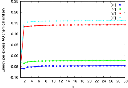
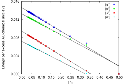
To extract the behavior of isolated stacking faults at infinite separation, we first determine the functional dependence of the interaction on the separation between stacking faults. Figure 9 shows the interaction energies of the stacking faults from Figure 8, now plotting these energies as a function of , where measures the separation between stacking faults in terms of the number of intervening bulk layers. The data in this figure exhibit clear linear behavior, indicating that the interaction is inversely proportional to fault separation. The ordinate intercepts (, or ) denote the energy released per excess AO chemical unit when stacking faults bind together into RP phases at their most energetically favored value of (for the two stable configurations within our model, and , with energy minima at ).
Table 5 summarizes the values of these binding energies per excess AO chemical unit, as determined by linear least-square fits to the energies for RP phases in Figure 9, ignoring in each case the three smallest separations () which clearly involve significant higher-order interactions. Even for the most attractive configuration (), our model shows a meV binding energy per octahedron neighboring the stacking fault (recall that there are two interfacial octahedra for each excess AO chemical unit, one on either side of the stacking fault), which is relatively low compared to room temperature, a fact which may be related to the observation of isolated faults in some materials.
| Configuration | Formation Energy [meV] |
|---|---|
| ‡ Meta-stable |
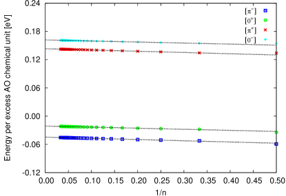
With the form of the interaction now determined, we turn to the formation energies of isolated stacking faults in their various configurations. We can now finally determine whether these different configurations have a large effect on formation energies of RP phases, as Section V.1 suggests. Figure 10 shows the formation energy per excess AO chemical unit as a function of .
Here, the ordinate intercepts give the energy to incorporate an AO chemical unit into an isolated, excess AO plane in perovskite relative to that chemical unit appearing in bulk A-oxide. Table 6 summarizes the formation energies of isolated stacking faults as determined by the same type of linear least-square fit used to extract the binding energies above. Within our model, we again find significant differences in formation energies between the two groupings of configurations (those with positive and negative energies), of up to meV per excess AO chemical unit or meV per oxygen octahedron neighboring the stacking fault. We also identify a much smaller energy difference between the two lowest-energy configurations (those with negative energies) of meV per excess AO chemical unit, or meV per octahedron. Following a similar argument as in Section V.1, for a range of temperatures above the bulk phase transitions, we may still find that octahedra near isolated stacking faults are constrained to a subset of low-energy rotational orientations, while those in the bulk fluctuate among all possible rotations.
Finally, comparing the results in Table 6 with those in Table 5, we come to the commonsensical, though not logically necessary, result that the sequence of stacking faults from the most stable (i.e., lowest formation energy) to the least stable, directly corresponds to the sequence of binding strengths, from the strongest attraction to the weakest. We also propose a simple physical mechanism for differentiating between higher and lower energies of formation for the configurations, potentially reflecting their stability relative to phase separation into bulk perovskite and bulk A-oxide. Figure 11 depicts the planar movement of oxygens in the AO layers on opposite sides of the stacking fault. The sense of rotation of the interfacial octahedra drives constituent oxygen ions to move in specific patterns within their respective AO layers along the stacking fault. For the high-energy configurations, or , the interfacial oxygen ions from opposite AO layers are displaced toward each other, despite their natural Coulombic repulsion, as in Figure 11(a). For the low-energy configurations in Figure 11(b), or , the same oxygen ions move past each other along the interface, tending to lessen the approach of like-charged ions toward one another and thus minimizing the energy. Thus, we find that the stability of different stacking-fault configurations can be readily understood in terms of simple Coulombic effects.
V.4 Point defects
With the energies of the various RP phases now determined, we are finally in a position to substantiate the claim that, in A-rich stoichiometries of ABO3, the RP phases are preferred over the formation of point defects.
Interstitials in perovskites are known to be energetically very unfavorableBalachandran and Eror (1982). On the other hand, A-rich stoichiometries can be understood by noting that the addition of an AO chemical unit is identical to the incorporation of a bulk ABO3 chemical unit followed by the removal of a BO2 chemical unit, the latter step forming a BO2 vacancy complex. To decide whether this formation of vacancies is more or less favorable than the incorporation of excess AO chemical units into planar stacking faults of the type in RP phases, great care must be taken to accurately balance stoichiometries.
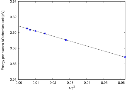
In the current context, we have been considering the excess AO chemical units originating from an external reservoir of A-oxide. To maintain a consistent chemical potential, the formation energy of an isolated BO2 vacancy in bulk perovskite must be computed as the energy first to remove an extra AO chemical unit from bulk A-oxide, and then to insert it into a large supercell containing chemical units of ABO3. Expressed mathematically, the energy of formation of this vacancy is
| (6) | ||||
where . As the final equality in (6) indicates, the energy of formation of an isolated BO2 vacancy in bulk perovskite is equivalent to the energy of a BO2 vacancy in an initial bulk cell containing chemical units of ABO3 relative to the energy of chemical units of ABO3 and one chemical unit of AO.
Figure 12 presents computed as described above, for (corresponding to a series of supercells of size primitive unit cells on a side, with between and atoms each), plotted as a function of . Following a least-squares fit, the unambiguous linear behavior in the plot indicates that the net interaction decays as , with the ordinate intercept (, or ) providing the extracted value of for the incorporation of excess AO as fully isolated BO2 vacancy complexes. The result within our model is eV per excess AO unit, far exceeding the energy of formation for even the least favorable RP phase configuration ( meV per excess AO chemical unit for in the configuration). The positive sign and large magnitude of this energy indicate that A-rich ABO3 will preferentially form planar AO stacking faults rather than isolated BO2 vacancy complexes. This result supports the present work’s focus on such stacking faults and RP phases.
VI Summary and conclusion
This work presents a detailed and exhaustive study of the zero-temperature structures of the homologous An+1BnO3n+1 series of Ruddlesden–Popper (RP) phases in a model antiferrodistortive perovskite for the greatest range of considered to date. We also consider, for a specific Glazer system, all possible octahedral orientations within RP phases of the material. Our work introduces and follows a general program which may be replicated for RP phases of perovskites within any Glazer system and applied in both ab initio and empirical potential studies.
We begin our particular considerations with a careful enumeration and symmetry analysis for all thirty-two combinatorially possible configurations of octahedral rotations within RP phases of an Glazer system. Symmetry arguments reduce these thirty-two possibilities to five distinct configurations, which we denote as , , , , and .
We then proceed to determine, within a shell-potential model, the ground-state structures of these five symmetry-distinct configurations for all values of . We find that, for our specific model, only four configurations are actually distinct, as one of the configurations () is unstable to immediate relaxation to another configuration (). After additional perturbation and quenching tests, we identify three of these remaining configurations as stable (, , ), and one as meta-stable (). In agreement with experimental observation across a range of perovskites, we find that, for all values of , all of the configurations of RP phases provide a much more stable option for the incorporation of excess A-oxide than the formation of point defects, such as BO2 vacancy complexes. We also find that, within our model, the two most stable configurations ( and ) lead to stacking faults which are energetically preferred over phase separation into the bulk perovskite and bulk A-oxide. Both of these findings are consistent with the experimental observation of RP phases in a wide variety of antiferrodistortive perovskites, including titanates, ruthenates, manganites, and niobates.
In terms of the interactions between stacking faults, we find that the interaction varies inversely with the distance between excess AO planes, a result which we believe to be generic, at least for the system. For our particular model perovskite, the form of the interaction between stacking faults is attractive. In perovskites with such an attractive interaction, we find that ABO3 with relatively low stoichiometric excess of species A manifests intergrowths between the RP phase and bulk perovskite. When such intergrowths are observed experimentally, the interaction is likely attractive in correspondence with our model material.
Additionally, we observe that the five symmetry-distinct configurations have significant differences in energies of formation: meV per rotational degree of freedom for our model perovskite, appreciably greater than the energy scales associated with orientational disorder in our model perovskite, – meV. This leads to an intriguing conjecture. For low densities of stacking faults within some perovskites, for a range of temperatures above their orientational phase transitions, the octahedra in bulk regions would exhibit randomized behavior about a high-symmetry mean configuration while octahedra near stacking faults would exhibit more ordered behavior about a lower-symmetry mean. Alternatively, for higher densities of such faults, this increase in energy scale would correlate to an increase of the transition temperatures associated with octahedral rotations. These effects may be particularly noticeable in materials with higher orientational energy scales than our model perovskite, such as lanthanum aluminate with its transition temperature of K.
Finally, we propose a simple physical mechanism to explain the strong dependence of the interfacial energy on the rotational state of the octahedra: some configurations result in movement of neighboring like-charged oxygen ions directly toward each other and thus are high in energy, whereas others result in movement of oxygen ions past each other and thus are low in energy.
Acknowledgements.
The authors are grateful for interesting conversations with David Roundy, Johannes Lischner, and JeeHye Lee. This work was supported by the Cornell Center for Materials Research (CCMR) with funding from the Materials Research Science and Engineering Center (MRSEC) program of the National Science Foundation (cooperative agreement DMR 0520404).References
- Barrett (1952) J. H. Barrett, Phys. Rev. 86, 118 (1952).
- Hegenbarth (1964) E. Hegenbarth, Phys. Status Solidi 6, 333 (1964).
- Samara (1990) G. A. Samara, J. Appl. Phys. 68, 4214 (1990).
- Shevlin et al. (2005) S. A. Shevlin, A. Curioni, and W. Andreoni, Phys. Rev. Lett. 94, 146401 (2005).
- Bednorz and Müller (1984) J. G. Bednorz and K. A. Müller, Phys. Rev. Lett. 52, 2289 (1984).
- Cohen (1992) R. E. Cohen, Nature 358, 136 (1992).
- Haertling (1999) G. H. Haertling, J. Am. Ceram. Soc. 82, 797 (1999).
- Chan et al. (1981) N.-H. Chan, R. K. Sharma, and D. M. Smyth, J. Electrochem. Soc. 128, 1762 (1981).
- Eror and Balachandran (1982) N. G. Eror and U. Balachandran, J. Am. Ceram. Soc. 65, 426 (1982).
- Frederikse et al. (1964) H. P. R. Frederikse, W. R. Thurber, and W. R. Hosler, Phys. Rev. 134, A442 (1964).
- Nakamura et al. (1971) T. Nakamura, S. Kose, and T. Sata, J. Phys. Soc. Jpn. 31, 1284 (1971).
- Schooley et al. (1964) J. F. Schooley, W. R. Hosler, and M. L. Cohen, Phys. Rev. Lett. 12, 474 (1964).
- Schooley et al. (1965) J. F. Schooley, W. R. Hosler, E. Ambler, J. H. Becker, M. L. Cohen, and C. S. Koonce, Phys. Rev. Lett. 14, 305 (1965).
- Koonce et al. (1967) C. S. Koonce, M. L. Cohen, J. F. Schooley, W. R. Hosler, and E. R. Pfeiffer, Phys. Rev. 163, 380 (1967).
- Arai et al. (1986) H. Arai, T. Yamada, K. Eguchi, and T. Seiyama, Appl. Catal. 26, 265 (1986).
- Teraoka et al. (1990) Y. Teraoka, H. Fukuda, and S. Kagawa, Chem. Lett. 19, 1 (1990).
- Peña and Fierro (2001) M. A. Peña and J. L. G. Fierro, Chem. Rev. 101, 1981 (2001).
- Ramirez (1997) A. P. Ramirez, J. Phys.: Condens. Matter 9, 8171 (1997).
- Obata et al. (1999) T. Obata, T. Manako, Y. Shimakawa, and Y. Kubo, Appl. Phys. Lett. 74, 290 (1999).
- De Teresa et al. (1999) J. M. De Teresa, A. Barthélémy, A. Fert, J. P. Contour, F. Montaigne, and P. Seneor, Science 286, 507 (1999).
- Ziese (2002) M. Ziese, Rep. Prog. Phys. 65, 143 (2002).
- Joshi and Krupanidhi (1993) P. C. Joshi and S. B. Krupanidhi, J. Appl. Phys. 73, 7627 (1993).
- Hwang et al. (1995) C. S. Hwang, S. O. Park, C. S. Kang, H.-J. Cho, H.-K. Kang, S. T. Ahn, and M. Y. Lee, Jpn. J. Appl. Phys. 34, 5178 (1995).
- Mantese et al. (1995) J. V. Mantese, N. W. Schubring, A. L. Micheli, and A. B. Catalan, Appl. Phys. Lett. 67, 721 (1995).
- Van Keuls et al. (1997) F. W. Van Keuls, R. R. Romanofsky, D. Y. Bohman, M. D. Winters, F. A. Miranda, C. H. Mueller, R. E. Treece, T. V. Rivkin, and D. Galt, Appl. Phys. Lett. 71, 3075 (1997).
- McKee et al. (1998) R. A. McKee, F. J. Walker, and M. F. Chisholm, Phys. Rev. Lett. 81, 3014 (1998).
- Edge et al. (2004) L. F. Edge, D. G. Schlom, S. A. Chambers, E. Cicerrella, J. L. Freeouf, B. Holländer, and J. Schubert, Appl. Phys. Lett. 84, 726 (2004).
- Yamamichi et al. (1994) S. Yamamichi, H. Yabuta, T. Sakuma, and Y. Miyasaka, Appl. Phys. Lett. 64, 1644 (1994).
- Taylor et al. (2003) T. R. Taylor, P. J. Hansen, N. Pervez, B. Acikel, R. A. York, and J. S. Speck, J. Appl. Phys. 94, 3390 (2003).
- Balachandran and Eror (1982) U. Balachandran and N. G. Eror, J. Mater. Sci. 17, 2133 (1982).
- Smyth (1985) D. M. Smyth, Annu. Rev. Mater. Sci. 15, 329 (1985).
- Witek et al. (1984) S. Witek, D. M. Smyth, and H. Pickup, J. Am. Ceram. Soc. 67, 372 (1984).
- Ruddlesden and Popper (1957) S. N. Ruddlesden and P. Popper, Acta Crystallogr. 10, 538 (1957).
- Ruddlesden and Popper (1958) S. N. Ruddlesden and P. Popper, Acta Crystallogr. 11, 54 (1958).
- Kwestroo and Paping (1959) W. Kwestroo and H. A. M. Paping, J. Am. Ceram. Soc. 42, 292 (1959).
- Haeni et al. (2001) J. H. Haeni, C. D. Theis, D. G. Schlom, W. Tian, X. Q. Pan, H. Chang, I. Takeuchi, and X.-D. Xiang, Appl. Phys. Lett. 78, 3292 (2001).
- Lee et al. (2007) K. H. Lee, Y. F. Wang, S. W. Kim, H. Ohta, and K. Koumoto, Int. J. Appl. Ceram. Technol. 4, 326 (2007).
- Liang et al. (2008) Z. Liang, K. Tang, Q. Shao, G. Li, S. Zeng, and H. Zheng, J. Solid State Chem. 181, 964 (2008).
- Maeno et al. (1994) Y. Maeno, H. Hashimoto, K. Yoshida, S. Nishizaki, T. Fujita, J. G. Bednorz, and F. Lichtenberg, Nature 372, 532 (1994).
- Grigera et al. (2001) S. A. Grigera, R. S. Perry, A. J. Schofield, M. Chiao, S. R. Julian, G. G. Lonzarich, S. I. Ikeda, Y. Maeno, A. J. Millis, and A. P. Mackenzie, Science 294, 329 (2001).
- Perry et al. (2001) R. S. Perry, L. M. Galvin, S. A. Grigera, L. Capogna, A. J. Schofield, A. P. Mackenzie, M. Chiao, S. R. Julian, S. I. Ikeda, S. Nakatsuji, et al., Phys. Rev. Lett. 86, 2661 (2001).
- Cao et al. (1997) G. Cao, S. K. McCall, J. E. Crow, and R. P. Guertin, Phys. Rev. B 56, R5740 (1997).
- Moritomo et al. (1996) Y. Moritomo, A. Asamitsu, H. Kuwahara, and Y. Tokura, Nature 380, 141 (1996).
- Meyer et al. (2006) D. C. Meyer, A. A. Levin, T. Leisegang, E. Gutmann, P. Paufler, M. Reibold, and W. Pompe, Appl. Phys. A 84, 31 (2006).
- Schlom et al. (1990) D. G. Schlom, J. N. Eckstein, I. Bozovic, Z. J. Chen, A. F. Marshall, K. E. von Dessonneck, and J. S. Harris, Jr., in Growth of Semiconductor Structures and High-Tc Thin Films on Semiconductors, edited by A. Madhukar (SPIE, 1990), vol. 1285, pp. 234–247.
- Klausmeier-Brown et al. (1992) M. E. Klausmeier-Brown, G. F. Virshup, I. Bozovic, J. N. Eckstein, and K. S. Ralls, Appl. Phys. Lett. 60, 2806 (1992).
- Peña et al. (1994) O. Peña, F. LeBerre, M. Sergent, R. Horyń, and A. Wojakowski, Physica C 235–240, 771 (1994).
- Bader et al. (1998) S. D. Bader, R. M. Osgood III, D. J. Miller, J. F. Mitchell, and J. S. Jiang, J. Appl. Phys. 83, 6385 (1998).
- Tilley (1977) R. J. D. Tilley, J. Solid State Chem. 21, 293 (1977).
- Ramesh et al. (1990) R. Ramesh, S. Jin, and P. Marsh, Nature 346, 420 (1990).
- Schilling et al. (1993) A. Schilling, M. Cantoni, J. D. Guo, and H. R. Ott, Nature 363, 56 (1993).
- McCarthy et al. (1969a) G. J. McCarthy, W. B. White, and R. Roy, J. Am. Ceram. Soc. 52, 463 (1969a).
- Iwazaki et al. (1999) Y. Iwazaki, T. Suzuki, S. Sekiguchi, and M. Fujimoto, Jpn. J. Appl. Phys. 38, L1443 (1999).
- Iwazaki et al. (2000) Y. Iwazaki, T. Suzuki, S. Sekiguchi, and M. Fujimoto, Jpn. J. Appl. Phys. 39, L303 (2000).
- Shibuya et al. (2008) K. Shibuya, S. Mi, C.-L. Jia, P. Meuffels, and R. Dittmann, Appl. Phys. Lett. 92, 241918 (2008).
- Tanaka and Kawai (2000) H. Tanaka and T. Kawai, Appl. Phys. Lett. 76, 3618 (2000).
- Tian et al. (2001) W. Tian, X. Q. Pan, J. H. Haeni, and D. G. Schlom, J. Mater. Res. 16, 2013 (2001).
- Fisher et al. (2007) P. Fisher, S. Wang, M. Skowronski, P. A. Salvador, M. Snyder, and O. Maksimov, Appl. Phys. Lett. 91, 252901 (2007).
- Suzuki et al. (2000) T. Suzuki, Y. Nishi, and M. Fujimoto, Philos. Mag. A 80, 621 (2000).
- Udayakumar and Cormack (1988) K. R. Udayakumar and A. N. Cormack, J. Am. Ceram. Soc. 71, C469 (1988).
- McCoy et al. (1997) M. A. McCoy, R. W. Grimes, and W. E. Lee, Philos. Mag. A 75, 833 (1997).
- Fennie and Rabe (2003) C. J. Fennie and K. M. Rabe, Phys. Rev. B 68, 184111 (2003).
- Suzuki and Fujimoto (2001) T. Suzuki and M. Fujimoto, J. Appl. Phys. 89, 5622 (2001).
- Le Bacq et al. (2006) O. Le Bacq, E. Salinas, A. Pisch, C. Bernard, and A. Pasturel, Philos. Mag. 86, 2283 (2006).
- Noguera (2000) C. Noguera, Philos. Mag. Lett. 80, 173 (2000).
- Weng et al. (2006) H. Weng, Y. Kawazoe, X. Wan, and J. Dong, Phys. Rev. B 74, 205112 (2006).
- Reshak et al. (2008) A. H. Reshak, S. Auluck, and I. Kityk, Jpn. J. Appl. Phys. 47, 5516 (2008).
- Music and Schneider (2008) D. Music and J. M. Schneider, J. Phys.: Condens. Matter 20, 055224 (2008).
- Elcombe et al. (1991) M. M. Elcombe, E. H. Kisi, K. D. Hawkins, T. J. White, P. Goodman, and S. Matheson, Acta Crystallogr. B47, 305 (1991).
- Aleksandrov and Bartolome (1994) K. S. Aleksandrov and J. Bartolome, J. Phys.: Condens. Matter 6, 8219 (1994).
- Hatch et al. (1989) D. M. Hatch, H. T. Stokes, K. S. Aleksandrov, and S. V. Misyul, Phys. Rev. B 39, 9282 (1989).
- Glazer (1972) A. M. Glazer, Acta Crystallogr. B28, 3384 (1972).
- Geller and Bala (1956) S. Geller and V. B. Bala, Acta Crystallogr. 9, 1019 (1956).
- Harley et al. (1973) R. T. Harley, W. Hayes, A. M. Perry, and S. R. P. Smith, J. Phys. C 6, 2382 (1973).
- Moreau et al. (1970) J.-M. Moreau, C. Michel, R. Gerson, and W. J. James, Acta Crystallogr. B26, 1425 (1970).
- Glazer (1975) A. M. Glazer, Acta Crystallogr. A31, 756 (1975).
- Megaw and Darlington (1975) H. D. Megaw and C. N. W. Darlington, Acta Crystallogr. A31, 161 (1975).
- Unoki and Sakudo (1967) H. Unoki and T. Sakudo, J. Phys. Soc. Jpn. 23, 546 (1967).
- Fleury et al. (1968) P. A. Fleury, J. F. Scott, and J. M. Worlock, Phys. Rev. Lett. 21, 16 (1968).
- Shirane and Yamada (1969) G. Shirane and Y. Yamada, Phys. Rev. 177, 858 (1969).
- Pytte and Feder (1969) E. Pytte and J. Feder, Phys. Rev. 187, 1077 (1969).
- Feder and Pytte (1970) J. Feder and E. Pytte, Phys. Rev. B 1, 4803 (1970).
- Scott (1974) J. F. Scott, Rev. Mod. Phys. 46, 83 (1974).
- Cochran (1961) W. Cochran, Adv. Phys. 10, 401 (1961).
- Müller et al. (1968) K. A. Müller, W. Berlinger, and F. Waldner, Phys. Rev. Lett. 21, 814 (1968).
- Axe et al. (1969) J. D. Axe, G. Shirane, and K. A. Müller, Phys. Rev. 183, 820 (1969).
- Thomas and Müller (1968) H. Thomas and K. A. Müller, Phys. Rev. Lett. 21, 1256 (1968).
- Lee (2008) J. Lee, private communication (2008).
- Lytle (1964a) F. W. Lytle, in Advances in X-Ray Analysis, edited by W. M. Mueller, G. Mallett, and M. Fay (Plenum Press, 1964a), vol. 7, pp. 136–145.
- Lytle (1964b) F. W. Lytle, J. Appl. Phys. 35, 2212 (1964b).
- Alefeld (1969) B. Alefeld, Z. Phys. 222, 155 (1969).
- von Waldkirch et al. (1973) T. von Waldkirch, K. A. Müller, and W. Berlinger, Phys. Rev. B 7, 1052 (1973).
- Scott (1969) J. F. Scott, Phys. Rev. 183, 823 (1969).
- Scott (1970) J. F. Scott, Phys. Rev. B 1, 942 (1970).
- Howard et al. (2000) C. J. Howard, B. J. Kennedy, and B. C. Chakoumakos, J. Phys.: Condens. Matter 12, 349 (2000).
- Goldschmidt (1926) V. M. Goldschmidt, Skrifter Norske Videnskaps-Akad. i Oslo, I. Mat. Natur. Kl. 8, 1 (1926).
- Galasso (1969) F. S. Galasso, Structure, Properties and Preparation of Perovskite-Type Compounds (Pergamon Press, Oxford, UK, 1969), pp. 3–11.
- Shannon (1976) R. D. Shannon, Acta Crystallogr. A32, 751 (1976).
- McCarthy et al. (1969b) G. J. McCarthy, W. B. White, and R. Roy, J. Inorg. Nucl. Chem. 31, 329 (1969b).
- Dick and Overhauser (1958) B. G. Dick, Jr. and A. W. Overhauser, Phys. Rev. 112, 90 (1958).
- Akhtar et al. (1995) M. J. Akhtar, Z.-U.-N. Akhtar, R. A. Jackson, and C. R. A. Catlow, J. Am. Ceram. Soc. 78, 421 (1995).
- Buckingham (1958) R. A. Buckingham, Trans. Faraday Soc. 54, 453 (1958).
- Born and Mayer (1932) M. Born and J. E. Mayer, Z. Phys. 75, 1 (1932).
- Lennard-Jones (1931) J. E. Lennard-Jones, Proc. Phys. Soc. 43, 461 (1931).
- van der Waals (1873) J. D. van der Waals, Ph.D. thesis, University of Leiden (1873).
- Lewis and Catlow (1985) G. V. Lewis and C. R. A. Catlow, J. Phys. C 18, 1149 (1985).
- Catlow and Stoneham (1983) C. R. A. Catlow and A. M. Stoneham, J. Phys. C 16, 4321 (1983).
- Ewald (1921) P. P. Ewald, Ann. Phys. 369, 253 (1921).
- Darden et al. (1993) T. Darden, D. York, and L. Pedersen, J. Chem. Phys. 98, 10089 (1993).
- Essmann et al. (1995) U. Essmann, L. Perera, M. L. Berkowitz, T. Darden, H. Lee, and L. G. Pedersen, J. Chem. Phys. 103, 8577 (1995).
- Deserno and Holm (1998) M. Deserno and C. Holm, J. Chem. Phys. 109, 7678 (1998).
- Hestenes and Stiefel (1952) M. R. Hestenes and E. Stiefel, J. Res. Natl. Bur. Stand. 49, 409 (1952).
- Polak and Ribière (1969) E. Polak and G. Ribière, Rev. Fr. Inform. Rech. O. 3, 35 (1969).