RD efforts towards a neutrino factory
Abstract
The R&D efforts towards a neutrino factory are outlined with special emphasis on the muon cooling issue and the data collected for target optimization.
1 Introduction.
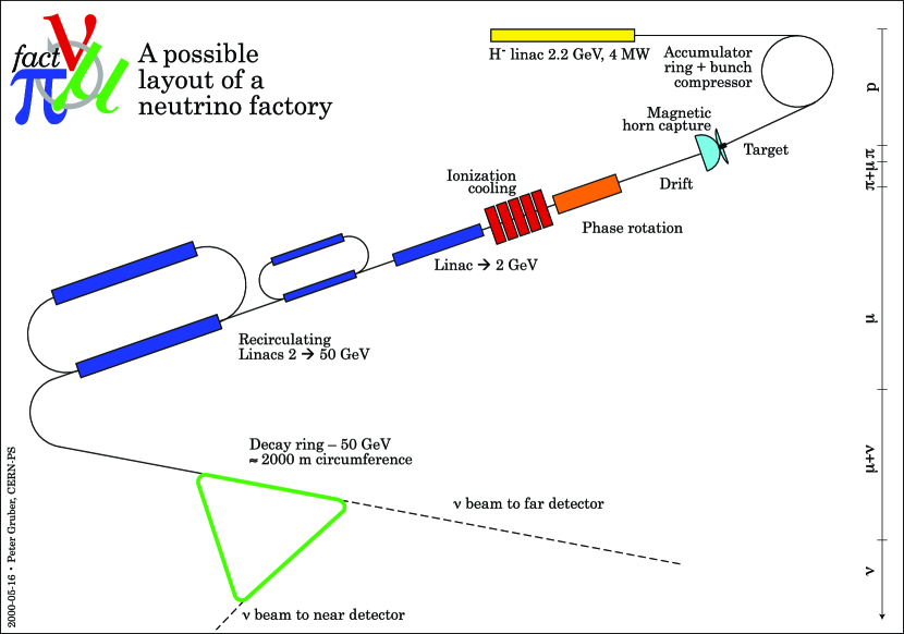
The neutrino factory () is a muon storage ring where decaying muons produce collimated neutrino beams along its straight sections. Several F designs have been proposed, such as the ones of references [1, 2]: the CERN design is shown in Figure 1. A high intensity beam accelerated by a high power proton driver produces in a thin Hg target, after some accumulation and bunch compression, low energy pions. After a collection system, muons are cooled and phase rotated before acceleration up to 20-50 GeV/c, depending on the design. Accelerated muons of well defined charge and momentum are then injected into an accumulator where they circulate until they decay, giving two neutrino beams along the straight sections.
The physics program at a neutrino factory is very rich and includes long-baseline oscillations, short-baseline physics and slow muon physics [3]. For the design of a F some key points have to be clarified with dedicated R&D experiments. They include targetry, both MC validation and feasibility studies of the target-pion collection complex, cooling and accelerator R&D (mainly the development of FFAG’s).
2 The target issue: the HARP experiment at CERN PS.
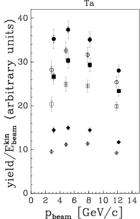
The baseline option for a F target is a Hg jet target with impinging particles at energies GeV. Available data are very scarce and for the tuning of the MC simulations of the F beamline the HARP data on heavy targets, such as Ta or Pb, are of utmost importance. In the kinematics range of interest for a F, the pion yield increases linearly with momentum and has an optimum between 5 GeV/c and 8 GeV/c, as shown in figure 2.

Final results for pion production on heavy targets have been published in reference [4] and an example of a comparison with available MC simulations is outlined in figure 3. None of the considered models describe fully HARP data. However, production is described better than production.
In a F, the produced pions are then collected through a magnetic horn or focussed through a superconducting solenoid (baseline design). The MERIT (MERcury Intense Target) experiment at CERN [5] has studied the feasibility of a mercury-jet target for a 4 MW proton beam with solenoidal pion capture, obtaining positive results.
3 The cooling issue: the MICE experiment at RAL.
The cooling of muons (accounting for of the final costs) increases the performances of a F up to a factor 10. Due to their short lifetime (s), novel methods such as the ionization cooling [6] must be used. The cooling of the transverse phase-space coordinates of a muon beam can be accomplished by passing it through an energy-absorbing material and an accelerating structure, both embedded within a focusing magnetic lattice. Both longitudinal and transverse momentum are lost in the absorber while the RF-cavities restore only the longitudinal component.
The MICE experiment [7] at RAL aims at a systematic study of one cell of the US Feasibility Study 2 cooling channel ( see figure 4 for its layout).

A secondary muon beam from ISIS (140-240 Mev/C central momentum) enters the cooling channel after a diffuser. Pions from a movable Ti target grazing the primary ISIS beam, during its flat top, are captured by a quadrupole triplet and then momentum selected. Muons from the following pion decays inside a 5m long, 5 T decay solenoid are momentum selected and directed towards the MICE apparatus. The 5.5 m long cooling section cell consists of three low-Z absorbers and eight 201 MHz RF cavities encircled by SC lattice solenoids, providing strong focussing. While hydrogen absorbers are the best, a more practical absorption media may be He, solid LiH or Be. Particles are measured before and after the cooling section by two magnetic spectrometers complemented by TOF detectors. For each particle the trackers determine x,y, x’=,y’= and t’= coordinates, while the TOF stations measure the time coordinate t. For an ensemble of N particles, the input and output emittances are thus measured with high precision (), at a level not within reach of conventional multiparticle methods.
The driving design criteria of the MICE beam instrumentation are robustness, in particular of the tracking detectors, to sustain the severe background conditions nearby the RFs and redundancy in PID in order to keep contaminations () well below . Each magnetic spectrometer consists of a superconducting 4 T solenoid of 40 cm bore, containing 5 planes of scintillating fiber detectors. Each station is composed of three doublet layers in stereo view arrangement.
Particle identification is obtained upstream the first solenoid by two TOF stations (TOF0/TOF1) and two aerogel Cherenkov counters (CKVa/CKVb). separation is obtained via the Cherenkov counters for momenta bigger than 210 MeV/c; below only the tof measurement is available. Downstream the PID is obtained via a further TOF station (TOF2) and an electromagnetic calorimeter (EMCAL). All downstream detectors and the TOF1 station must be shielded against stray magnetic fields from solenoids (up to 1000-1500 G with components along the PMT axis up to 400 G). While TOF1 will be shielded by a double-sided shielding cage that fully contains the detector, TOF2 and EMCAL PMT’s will be shielded locally by individual soft iron massive boxes. The TOF stations share a common design based on fast scintillator counters along X/Y directions (to increase measurement redundancy) read at both edges by fast R4998 Hamamatsu photomultipliers ( ps TTS, 0.7 ns risetime). A coincidence with TOF2 will select particles traversing the entire cooling channel. In addition the use of an electromagnetic calorimeter (EMCAL) will help to distinguish the genuine variation of emittance due to cooling from the one due to losses and decays.
The EMCAL is a Pb-scintillating fiber calorimeter (KL), of the KLOE type [8], with 1-mm diameter blue scintillating fibers glued between 0.3 mm thick grooved lead plates to be followed by a muon ranger (SW), made of a fully sensitive segmented scintillator block. This “spaghetti” design for KL offers the possibility of a fine sampling and optimal lateral uniformity. Both TOF (INFN MIB) and KL (INFN RM3) prototypes have been tested in the Frascati BTF testbeam with satisfactory results. As an example, the TOF counters intrinsic resolution was around 50 ps. Up to now, only the upstream PID detectors and KL are installed at RAL.
MICE will be accomplished in steps during two phases: first to characterize the incoming beam and demonstrating the capability to do a high precision measure of emittance (PHASE I) and then to measure the transverse cooling for a variety of experimental situations (PHASE II).
4 Conclusions
Experimental R&D results may soon strengthen the physics case for a F. Establishing the key techniques by the end of this decade, can pave the way to build a facility in the next one.
References
- [1] M.M. Alsharo’a et al., Phys. ReV. ST. Accel. Beams 6,081001 (2003).
- [2] A. Blondel et al., CERN-2004-002.
- [3] M. Bonesini, A. Guglielmi Phys. Rep. 433 (2006) 65.
- [4] M.G. Catanesi et al., HARP Collaboration, Phys. ReV. C77 (2008) 055207.
- [5] J. Bennet et al., MERIT proposal, CERN-INTC-2004-016.
- [6] A.N. Skrinsky, V.V. Parkhomchuk Sov. Jour. Nucl. Phys. 12 (1981) 3.
- [7] A. Blondel et al., MICE proposal, RAL, 2004; G. Gregoire et al., MICE Technical Report, RAL, 2005.
- [8] A. Aloisio et al., KLOE coll., Nucl. Inst. and Meth. A 494 (2002), 326.