Pulsar Navigation in the Solar System
Abstract
The X-ray Navigation and Autonomous position Verification (XNAV) is tested which use the Crab pulsar under the Space Test Program that use starlight refraction. It provide the way that the spacecraft could autonomously determine its position with respect to an inertial origin. Now we analysis the sensitivity of the exist instrument and the signal process that use radio pulsar navigation and discuss the integrated navigation which use radio pulsar, then give the different navigation mission analysis and design process basically which include the space, the airborne, the ship and the land of the planet or the lunar. Our analysis show that we will have the stability profile (signal-to-noise is 5 ) that use a 2 meters antenna observe some strong sources of radio pulsar in 36 minutes which based on the today’s technology. So the pulsar navigation can give the continuous position in deep space, that means we can freedom fly successfully in the solar system use celestial navigation that include pulsar and traditional star sensor. It also can less or abolish the dependence to Global Navigation Satellite System (GNSS) which include GPS, GRONSS, Galileo and BeiDou et al.
1 Introduction
The gigantic success of celestial navigation is Christopher Columbus awareness of the American continents in the Western Hemisphere in 1492, even if it first be discovered in 1421 by ZhengHe or Viking, they all use celestial navigation in the road. The history of navigation use celestial origin from the ancient activity which include hunting and back to home in the night. The base principle of celestial navigation is used the moon, stars, and planets as celestial guides assuming the sky was clear in that times.
With the period of the Age of Discovery or Age of Exploration (the early 15th century and continuing into the early 17th century), many new technique be invented which include water clock, quadrant Sextant (1731, John Hadley), Chronometer (1761, John Harrison), the Sumner Line or line of position (1837, Thomas Hubbard Sumner), the Intercept Method or Marcq St Hilaire method (1875, Marcq St Hilaire) et al. The Sumner Line and Marcq St Hilaire method construct the foundation of modern nautical navigation. The lighthouse are used to mark dangerous coastlines, hazardous shoals and reefs, safe entries to harbors and can also assist in aerial navigation. For the physics and chemistry development, Gustaf Dalén in recognition of his remarkable invention of automatic valves designed to be used in combination with gas accumulators in lighthouses and light-buoys (the noble prize in 1912).
After Guglielmo Marconi achieve the radio communication in 1895, navigation that use radio as an aid has been practiced in Germany since 1907. Scheller invent the complimentary dot-dash guiding path, which can be seen as a ‘landmark’ for several decades of navigational aids. The first practical VHF radar system be installed on French ship in 1935. Radio navigation grow fast for the defense technique need in the World War II, the LOng RAnge Navigation (Loran) system is invented. In 19 century, it is proposed that use artificial stellar navigation. Until 1960, the first satellite navigation system, Transit, is first successfully tested, used by the United States Navy. Then it evolve to Global Positioning System (GPS). The soviet also build the similar system - GLONASS for the same reason. Now the Global Navigation Satellite system (GNSS) in the realism or dreams still have BeiDou, GALILEO et al.
An Inertial Navigation System (INS) is a navigation aid that uses the computing and motion sensors to continuously track the position, orientation, and velocity (direction and speed of movement) of a moving object without the need for external references. The gyroscopic compass (or gyro compass) was introduced in 1907. In 1942, the first INS be applied in V2 missile, then it be used in aeronautics, nautical and space widely.
When GPS and INS is still not ripe, Celestial Navigation System (CNS) be spread to aeronautics by US (B-52, B-1B, B-2A, C-141A, SR-71, F22 et al.) and Soviet (TU-16, TU-95, TU-160 et al.) (Pappalardi et al., 2001; AnGuo, 2007). Then the star tracker (i.e. track one star or planet or angle between it) (McCanless, 1963) be used to determine the attitude of the spacecraft in help orient the Apollo spacecraft enroute to and from the Moon. Now the advanced star sensor (i.e. sense many star simultaneous) has been developed for the application of optical CCD technique (Kennel, Havstad and Hood, 1992).
Although GPS and INS almost can finish any job in this planet now, someone still think celestial navigation is important for it can be used independently of ground aids and has global coverage, it cannot be jammed (except by clouds) and does not give off any signals that could be detected by an the others. The traditional maritime state which include US, Russia, UK and French, all spend many money in CNS for its unique advantage.
2 X-ray Pulsar-based Navigation System in Spacecraft
After radio pulsar be discovered by Bell, J. and Hewish, A. in 1967, Downs, G. S. give the advice that use radio pulsars for interplanetary navigation in 1974 (Downs, 1974). But in that time, both the radio and optical signatures from pulsars have limitations that reduce their effectiveness for spacecraft navigation. At the radio frequencies that pulsars emit (from 100 MHz to a few GHz) and with their faint emissions, radio-based systems would require large antennas (on the order of 25 M in diameter or larger) to detect sources, which would be impractical for most spacecraft. Also, neighboring celestial objects including the sun, moon, Jupiter, and close stars, as well as distance objects such as radio galaxies, quasars, and the galactic diffuse emissions, are broadband radio sources that could obscure weak pulsar signals (Ray, Wood and Phlips, 2006; Sheikh, 2005; Sheikh et al., 2006). So Chester, T. J. and Butman, S. A. describe spacecraft navigation using X-ray pulsars in 1981 (Chester and Butman, 1981). Dr Wood, K. S. design the NRL-801 Unconventional Stellar Aspect Experiment (USA) experiment, give strategies for using information gathered by X-ray detectors to determine attitude and position that use occultation method of traditional celestial navigation, and timekeeping (Wood, 1993). Dr Hanson, J. E. give the plan of attitude determination algorithm and timekeeping that use phase-locked loop (Hanson, 1996). Then in the USA Experiment on the ARGOS, the X-ray Pulsar-based Navigation System (XPNAVS) be first tested which use the Crab pulsar between Feb 1999 and Nov 2000. In fact, USA experiment is Not Real X-ray pulsar-based navigation experiment for it is based on occultation method that depend on the earth atmospheric models (Wood et al., 2002). Dr Sheikh, S. I. et al. construct the X-ray pulsar-based autonomous navigation theory which based on modern spacecraft navigation technique that include Kalman filter et al. (Sheikh, 2005). In the same time, Woodfork, D. W. show that the accurate of the position and the clock will be improved if using pulsars to aid in a constellation Signal-In-Space Range Error (SISRE) reduction (Woodfork, 2005).
In XPNAVS, the stability of pulsar as one beacon and kalman filter to represent the vehicle state lay the foundation for the navigation. Figure. 1 show the principle of Sheikh’s pulsar navigation theory. Pulsar as the nature lighthouse provide a continuous periodic signal. Then all signal be normalizing to solar system barycenter coordinates (SSBC). Though calculate the phase difference of pulsar’s times-of-arrival (TOA), that observed by spacecraft, we will have position and velocity by a vector computing in SSBC (Sheikh and Pines, 2006; Golshan and Sheikh, 2007; Sheikh, Ray, Weiner, Wolff and Wood, 2007; Sheikh, Golshan and Pines, 2007; Sala et al., 2004). The satellite’s amplitude will gain by the same way of star sensor (Ray, Wood and Phlips, 2006; Sheikh et al., 2006).
2.1 Pulsar Clock for Timing
In 1971, Reichley, et al. described using radio pulsars as clocks (Reichley, Downs and Morris, 1971). With researching in-depth, radio astronomer build a stand template to pulsar timing (Downs, 1981; Backer and Hellings, 1986). The character of pulsar spin be understood more deeply with the timing time increase. Pulsar especially millisecond pulsars (MSP) be thought the nature’s most stable clock (Taylor, 1991). The data show some pulsar stability than atomic clock in the timescale greater than one year (Matsakis, Taylor and Eubanks, 1997). So pulsar time not only is one independent clock to spacecraft (Hanson, 1996) but also even can inject to GPS in a long term (Woodfork, 2005). But currently utilized methods of timing pulse have errors on the order of hundreds of nanoseconds based upon their implementation simplifications, which should be addressed if improved accuracies are required (Sheikh, Hellings and Matzner, 2007).
2.2 Kalman filter for Position and Velocity
The kalman filter is an efficient recursive linear filter that estimates the state of a dynamic system from a series of noisy measurements (Kalman, 1960). It can predict the motion of anything for it is recursive, even the signal have noise, for that use the dynamic state estimate the system. (Though Thiele, T. N. and Swerling, P. developed a similar algorithm earlier, that is Kalman suggest the applicability of his ideas to the problem of trajectory estimation for the Apollo program, leading to its incorporation in the Apollo navigation computer.) Kalman filter is an important topic in control theory and control systems engineering, and an important method of least-squares estimation (Sorenson, 1970). It is used in a wide range of engineering applications which include radar tracking, control system, communication, guiding and navigation, computer vision, prediction in weather and economy, biomedicine, robot et al. In XPNAVS, that is significant like it in INS and the traditional CNS (i.e. star sensor). We can use navigation kalman filter measure pulsar range and phase, spacecraft clock, then compare with the signal which come from pulsar, so we will have position and velocity (Sheikh and Pines, 2006; Golshan and Sheikh, 2007; Sheikh, Ray, Weiner, Wolff and Wood, 2007; Sheikh, Golshan and Pines, 2007; Sala et al., 2004).
In the future XPNAVS, the system noise can not be ignore which origin from all signal processing (Hanson et al., 2008). Pulsar’s proper motion must be accurate measurement for we must know the beacon position first (McGary et al., 2001; Chatterjee et al., 2004). That must be point which use one pulsar also can finish XPNAVS if integrate with INS or star sensor.
3 Navigation use Radio Pulsar
When Downs, G. S. advise that use radio pulsars for interplanetary navigation in 1974, the antenna and electronic technique can not finish this job and pulsar signal process has been understood roughly (Lorimer and Kramer, 2005; Lyne and Graham-Smith, 2006). In 1988, Wallace, K. has planned use of radio stars that include pulsar for all weather navigation (Wallace, 1988). But it is still impossible job on technology in that time. In fact, just radiometric sextant is widely applied on submarine and aircraft carrier et al. in US and Soviet, for example the Cod Eye (Polmar and Noot, 1991).
Now we think the exist instrument can achieve radio pulsar navigation although micro-strip antennas can not do it (Sala et al., 2004). The reason that is the technology development and pulsar signal process be cognized more deeply (Lorimer and Kramer, 2005; Lyne and Graham-Smith, 2006; Hankins and Rickett, 1975; Rickett, 1990).
3.1 Pulsar signal process in astronomy Vs The requires of engineer project Vs The reliable of technique
The sensitivity of radio pulsar observation system (i.e. the raw limiting flux density) is given by the radiometer equation (Lorimer and Kramer, 2005; Lyne and Graham-Smith, 2006):
| (1) |
here is a loss factor, taken to be 1.5 (One-bit sampling at the Nyquist rate introduces a loss of relative to a fully sampled signal. The principal remaining loss results from the non-rectangular bandpass of the channel filters.), is the detection signal-to-noise ratio threshold, taken to be 5.0, is the receiver bandwidth in Hz, is the number of polarizations, is the time per observation in seconds, is pulsar period, is pulse width (), is the system temperature, is the telescope gain, , here the effective area of a telescope, is Boltzmann’s constant.
From the above described, we can use low-noise receivers, a relatively wide bandwidth and long observation times to observed pulsar although it is relatively weak radio sources if there are not a large radio telescope. Using the equation 1, we use 2 M antenna (If the telescope efficiency is 0.4, , ), is 40 K, 28 GHz bandwidth (2 G - 30 G), is 2, is 36 min, so we have . The table 1 is the list of the strong radio pulsar source, it show that we can observed those pulsars which use 2 meter antenna in 36 minutes. If we set is 4 min, 4 M antenna, we have .
The above formula use Jy as unit. The Jansky (Jy) is a measure of spectral power flux density - the amount of RF energy per unit time per unit area per unit bandwidth, . The jansky is not used outside of radio astronomy. It is not a practical unit for measuring communications signals, the magnitude is much too small, and is a linear unit, Very few RF engineers outside of radio astronomy will know what a Jy is. Because of wide dynamic range encountered the most radio systems, the power is usually expressed in logarithmic units of watts (dBW) or milliwatts (dBm): , . While not comprised of the same units, we can make some reasonable assumptions to compare a Jy to dBm. Assumptions bandwidth is 28 GHz (2 G - 30 G), 14 GHz frequency (), parabolic receive antenna, antenna collecting area . How much is one Jy worth in dBm ? , . Considering the parabolic antenna as a circular aperture gives the following approximation for the maximum gain: . in this form, is power gain over isotropic is reflector diameter in same units as wavelength, is the center of wavelength. For 2 M diameter and , . So 1 Jy in 2 M antenna is . May be the signal intensity is small for RF engineers, but for pulsar which like the periodic Gaussian signal, we can fold it in the integrate time to increase the pulsar singal sensitivity.
Pulsar signal suffer dispersion due to the presence of charged particles in the interstellar medium. The dispersion delay across a bandwidth of centred at a frequency is
| (2) |
where the dispersion measure, DM, is in units of and the frequencies are in MHz. To retain sensitivity, especially for short-period, high-dispersion pulsars, the observing bandwidth must be sub-divided into many channels to use to incoherent dedispersion or achieve the coherent dedispersion (Hankins and Rickett, 1975). Now a filterbank system have been developed to Digital Filterbank (DFB) which base field-programmable gate array (FPGA). The coherent system also enter a new times with multi-core and multi-PC cluster development and the price of PC decrease. In recently, the advantage of graphics processing unit (GPU) and FPGA in computing be attracted, if we can fuse Multi-core CPU, GPU and FPGA, construct one computing server and use the different advantage of it, that will easily finish many scientific computation which include coherent dedispersion.
In XPNAVS, they use the TOA Measurements of pulsar gain the position (Sheikh and Pines, 2006). In radio waveband, can we not only use the TOA but also use the single pulse of pulsar if the antenna is enough big, for example, in SIGINT (SIGnals INTelligence) satellite. Navigation using pulsar single pulse different with XPNAVS use the TOA, that will have more precision than use the TOA for it direct access to phase information that less the error in the measuring process. Using the above equation 1, we use 50 M antenna (If the telescope efficiency is 0.35, , ), is 40 K, 28 GHz bandwidth (2 G - 30 G), is 2, is 1 ms, so we have . The result show that we can observe the single pulse of pulsar in the table 1 that use 50 M antenna.
In radio pulsar, the strong flux density pulsar usually is young pulsar, for example Vela et al., but it take place glitch that is spin faster than past, that is abnormal phenomenon in pulsar timing model, then it become the biggest noise source. MSP is a kind of stability pulsar, but it often is weakly. Many MSP is in binary system, the signal be modulated by orbit effect. And many MSP in globe cluster, its position unstable for the complex gravitational potential.
Navigation of use pulsar just for a continuous pulse signal during the mission time which during tens of minutes to several years. When we penetrate the system of pulsar navigation as one systems engineering, we think navigation system use radio pulsar is feasible absolutely. Besides increasing the observation times et al., we think some modern digital signal processing (DSP) technique can apply to pulsar signal navigation which include signal enhancement, signal reconstruct and singularity detection et al. The hypothesis of pulsar signal is Gaussian be used in study pulsar emission geometry although it do not be validated directly by observation (Wu et al., 1998). In navigation, we just need the information from phase, so we can magnify the weak pulsar signal through plus a Gaussian signal or normalizing it to a Gaussian signal on the premise of keep period steadiness. Glitch can use wavelet to detect in time (Dong, 2009 in prepared) when use several strong radio pulsar in short time mission. So we can rule out the interference source, whether using single pulse or TOA. The navigation system must leave a copy of raw data to astronomer for the best filter is construct a good pulsar noise model by it.
3.2 Pulsar Tracker
The parabolic dish usually be used in radio astronomy. But the conventional telescope will bring the control problem in spacecraft because the big dish is so weight. Figure. 2 is a radio telescope in Nasu Pulsar Observatory which the same like Arecibo radio telescope in single dish (Takeuchi et al., 2005). It will less the difficult of control if use it in vehicle. So we can use this telescope achieve pulsar tracker like star tracker easily.
3.3 Pulsar Sensor
The phased array antenna or radar have seen in recent years breakthroughs that lead to capabilities not possible only a few years ago. This is exemplified by the development of GaAs integrated microwave circuits called monolithic microwave integrated circuits (MMIC) which makes it possible to build active electronically scanned arrays (AESAs) having lighter weight, smaller volume, higher reliability and lower cost (Brookner, 2007). Figure. 3 is AESAs of F22 which namely AN/APG-77 and built by Northrop Grumman. This phased array easy achieve pulsar sensor (i.e. observe several pulsar simultaneous) when it work in passive mode (Malas, 1997). The phased array feed also can apply in pulsar sensor when use one dish.
3.4 Pulsar Observation in Radio and X-Ray
When measuring the arrival times of pulsar, the TOA of a fiducial point in the rotational phase of a pulsar is the fundamental quantity which must be determined. This is normally done by comparison with a standard pulse profile . The observed pulse profile can be expressed in terms of the standard profile by where is a DC offset, is a scale factor, is a phase shift and represents noise. For the comparison, full use of the available signal to noise is most easily achieved by cross-correlating the observed and standard profiles in the Fourier domain. To do this a very accurate time standard is required and is usually obtained from a local hydrogen maser referenced to a standard bank of caesium clocks in the ground radio observation (Bell, 1998). But, it is not always possible to have a sufficiently accurate clock at the telescope, requiring regular determination of clock offsets. For example, the absolute time of RXTE’s clock is sufficiently accurate to allow this phase of the main X-ray pulse to be compared directly with the radio profile (Rots, Jahoda and Lyne, 2004). The reason that is atomic clock so bigger that can not be installed in satellite.
A fundamental reason for the provision of contemporary ephemerides for timing and searches at other wavelengths (non-radio) is that in many cases, less than one photon per pulse period is observed. For example the average separation between photons from the Crab when observed by EGRET is 10 minutes, which corresponds to about 18000 pulse periods (Bell, 1998). It is the reason that pulsar timing and search in radio waveband in usual. So pulsar timing in radio have the second advantage for have pulsar ephemerides that need long time timing observation. Pulsar timing in X-ray just about 15 years from RXTE be launched (Rots, Jahoda and Lyne, 2004). Pulsar timing in radio have over 40 years (Hobbs, Lyne and Kramer, 2010). If we want to use radio pulsar ephemerides in X-ray, we must study the phase difference in X-ray and radio use some years observation (Rots, Jahoda and Lyne, 2004; Livingstone et al., 2009).
The frame of reference is the foundation of measure the position, orientation, and other properties of objects in it. Now astronomer have built three reference frame in optic, radio and infrared that include FK5 and ICRF2 et al., still do not build it in X-ray band (Johnston and de Vegt, 1999). So radio pulsar will direct link to the reference frame in navigation.
3.5 Integrated Navigation with Pulsar
Integrated navigation with pulsar in CNS, INS or GNSS, is realistic path in the future mission. It will increase the reliability and redundancy of navigation or guiding system (GuoLiang and Jing, 2008). The multi-waveband pulsar navigation also is interested, for instance, use 1 meter optical telescope (Oosterbroek et al., 2008) or 1.2 meter infrared telescope (Ransom et al., 1994) can gain the crab pulsar profile, those observation system also easily load in one truck. In integrated navigation, system analysis and modeling, system state estimation, filter design, information synchronization and system fault tolerance filter design all is important.
4 Pulsar Navigation in the Solar System
Like giving different produce in different place by navigation systems division of Northrop Grumman Corporation, pulsar navigation also need use different system in each mission (Graven et al., 2007, 2008; Ray et al., 2008).
4.1 In the space based and the airborne
In deep space explore, X-ray pulsar tracker suitable for most small spacecraft in usually for it even can use a 30 cm detector have the crab pulsar profile. But it can not finish pulsar sensor mission now. We can have spacecraft attitude and position et al. from it. In International Space Station (ISS) or Laser Interferometer Space Antenna (LISA) et al., the biggest vehicle, the dish like Figure. 2 is well in mission time. In radio astronomy, we will have more accurate profile and timing in the same time which compare with X-ray astronomy for the different detection method. For some satellites in orbit which include GPS, the Tracking and Data Relay Satellite System (TDRSS) et al., that need precise time, radio tracker like Figure. 2 is a good choice for it will have a best clock in long term. SIGINT (SIGnals INTelligence) satellite is the biggest spaceborne antenna for intelligence-gathering by interception of signals, whether between people (i.e., COMINT or communications intelligence) or between machines (i.e., ELINT or electronic intelligence), or mixtures of the two. Its diameter even has 150 meters. Radio pulsar signal must be strong noise for it like Crab pulsar to the Ballistic Early Warning Site (BMEWS) of US Air Force (Schisler, 2008). For some airborne vehicle (F22, J20, B2 et al.) and sub-orbit spaceship (X37, X51 et al.), pulsar sensor like AN/APG-77 of F22 is best choice for its mission need change attitude frequently.
The Snark (SSM-A-3/B-62/SM-62, Northrop) is the only intercontinental surface-to-surface cruise missile (ICCMs) ever deployed by the US Air Force, but is operational for only a very short time because it was already made obsolete by the new Intercontinental Ballistic Missile (ICBMs). It first achieve CNS (star tracker) in astronautical. P-29 (i.e. SS-N-18, Stingray) is submarine-launched ballistic missile which first achieve one integrated navigation system between INS and CNS (star sensor), and it first be launched many simultaneous for have this integrated navigation system. The Snack and the Stingray both the large vehicle which easily equip pulsar tracker or sensor, and it can be used in reconstruct the solar system which include dig well in Mars for water et al. (McFadden, Weissman and Johnson, 2007). With the distance increase, the radiometric tracking of deep space network (DSN) will decrease in accuracy (Thornton and Border, 2005), and it can’t work when spacecraft in the other side of sun. But pulsar can’t be effected in that place.
4.2 At the shipboard and submarine
The big ship all have the radar or antenna for communication et al. (Brookner, 2007). Some special ship,for example Yuan Wang tracking ship, can use to test pulsar navigation in nautical. The interesting thing is whether it can be used in submarine for pulsar can be observed in 12.6 MHz (Bruck, 1987). Project 667 submarines (NATO reporting name Delta) are Soviet-built strategic nuclear missile submarines which have two VLF/ELF communication buoys. Navigation systems include SATNAV, SINS, Cod Eye (radiometric sextant), Pert Spring SATCOM (Polmar and Noot, 1991). It usually use the enormous antenna net (array underwater) to realize VLF/ELF communication, may be it can receive pulsar signal after a coherent dedispersion.
The higher frequency waves (that is, the shorter the wavelength), the more easily be absorbed by water. So radio signal reach deeper than optic, but the big antenna net is more difficulty than optic telescope in control. In project 667, missile tube about 2 meter, it can observe pulsar signal underwater if less one missile and built one 2 meter optic or infrared telescope which the same like solar tower. Those technique carry out will benefit to launch one submarine to the four gas giants (Jupiter, Saturn, Uranus, and Neptune) for understand hydro-geology and interiors et al. (McFadden, Weissman and Johnson, 2007).
4.3 On the land of planet and lunar
In the navigation system, the reliability and redundancy is very important. GPS is a system that spend a lot of money and high maintenance costs. So Ai GuoXiang et al. develop Chinese Area Positioning System (CAPS) that using the communication satellite (Ai et al., 2008) and Wang AnGuo made the navigation theory that based on the measurement of radio signal that from celestial and the carrier signal of man-made objects (AnGuo, 2007). The above system just can application in the earth, can not be used in the other planet. Even if in the earth, the phased array radar can easily moved, and the 2 meters radio telescope or 1.5 meters optical or infrared telescope can load in one truck easily. The same technique can use in lunar rover, Mars rover and rover in the others terrestrials, Mercury and Venus. The virtue is obvious, when the rover in the back of the others planet or lunar, DSN can not work and human can not built GNSS for the other planet in long term. So the radio pulsar navigation is one and only method at any place of the other planet surface day and night in the future explore.
5 Pulsar Navigation in the Human evolution to the Type II of Kardashev civilizations
Now Conventional Inertial Reference System (CIRS) is defined in the help of the International Celestial Reference Frame (ICRF) that is a quasi-inertial reference frame centered at the barycenter of the solar system, defined by the measured positions of extragalactic sources (mainly quasars). So it has very high accuracy and reliability. It will be direct, natural, reliable and accurate, if the navigation system be built on the celestial reference system. Therefor, CNS has some advantages, first it is passive measurement in autonomous navigation, second it has anti-interference ability and is highly reliable, third it has wide scope of application and the big space of the development, finally it has simple low-cost equipment and facilitate the application and popularization (AnGuo, 2007).
Traditional celestial navigation can be divided into optical stars navigation and radio stars navigation. In rainy, the conventional optical instruments can not observing the celestial bodies, the use of navigation time is limited. So optical celestial navigation difficult to achieve all-weather work, has always a serious obstacle to the application of skills. The round-the-clock work is a basic requirement by modern navigation system. The use of celestial bodies to achieve the astronomical radio navigation can be out of adverse weather conditions and restrictions on day and night light. As a result, the only way of celestial navigation is radio technology to accomplish the all-weather navigation. Traditional the equipment of radio celestial navigation is radio sextant, it only receive a small number of radio signal, thus difficult to achieve continuous navigation, and just have the low navigation accuracy, and the equipment size is very big. So it difficult to application and development. XNAV is developed by Sheikh et al. in recently, have achieve the preliminary results in X-ray band. Now the European Space Agency (ESA), Russia, France and German also have begun research it. However, these study limited to X-ray band, only can be used in spacecraft navigation. From the above analysis, the small antenna (even two meters) or the small optical or infrared telescope (even one meter), can receive the stable pulsar signal, which means that in radio, optical and infrared bands also can achieve the pulsar navigation. This work expanded the application range of pulsar navigation, made it can use in the aerospace, aviation, maritime, ground and underwater. So pulsar navigation avoid the disadvantage of the traditional radio celestial navigation technology.
In recently, Coll, B. and Tarantola, A. give the analysis of pulsar navigation in the Milky Way that base general relativity theory (Coll and Tarantola, 2009). If we can understand the effect of pulsar emission area, may be we can use it navigation in the Milky way.
Soviet astronomer Kardashev, N. S. propose a scheme for classifying advanced technological civilizations. He identified three possible types and distinguished between them in terms of the power they could muster for the purposes of interstellar communications. A Type I civilization would be able to marshal energy resources for communications on a planet-wide scale, equivalent to the entire present power consumption of the human race, or about watts. A Type II civilization would surpass this by a factor of approximately ten billion, making available watts, by exploiting the total energy output of its central star. Finally, a Type III civilization would have evolved far enough to tap the energy resources of an entire galaxy. This would give a further increase by at least a factor of 10 billion to about watts (Kardashev, 1964). Carl Sagan estimate that, on this more discriminating scale, the human race would presently qualify as roughly a Type 0.7. In the Age of Discovery, that is CNS make human freely voyage in the sea. So it make human civilization increase to higher type.
Now the Second Age of Discovery or Age of Exploration in the solar system is beginning, pulsar as nature beacon in the Milky Way will make human freely fly in the space of solar system. Recently, the first Falcon 9 flight is successfully launched on June 4, 2010 with a successful orbital insertion. It is a spaceflight launch system that uses rocket engines designed and manufactured by SpaceX company. Many private company of the aerospace industry for instance SpaceX and SpaceDev et al., need one low cost and reliable navigation system. Pulsar navigation give a path which do not depend on DSN, so it less huge cost in the outer space and the interplanetary navigation. It make the spacecraft of the private company not only enter the outer space but also voyage to the other planet. After some pioneer explore, if we can find one mode to gain profit, may be tour or dig ore that include in lunar and diamonds in Uranus and Neptune (Knudson, Desjarlais and Dolan, 2008), the new manufacturing about space travel will lead people into a new economic era, and the real Second Age of Discovery or Age of Exploration will begun. That is extraordinary in the human evolution to type II of Kardashev civilizations.
Acknowledgements
The author thank DARPA make someone invent Internet and open it for public.
References
- (1)
- Ai et al. (2008) Ai, G.X., H.L. Shi, H.T. Wu, Y.H. Yan, Y.J. Bian, Y.H. Hu, Z.G. Li, J. Guo and X.D. Cai. 2008. “A Positioning System based on Communication Satellites and the Chinese Area Positioning System (CAPS).” Chin. J. Astron. Astrophys 8(6):611–630.
- AnGuo (2007) AnGuo, Wang. 2007. “Modern Celestial Navigation and the Key Techniques.” Acta Electronica Sinica(Chinese) 35(12):2347–2353.
- Backer and Hellings (1986) Backer, D. C. and R. W. Hellings. 1986. “Pulsar timing and general relativity.” ARA&A 24:537–575.
- Bell (1998) Bell, J. F. 1998. “Radio pulsar timing.” Advances in Space Research 21:137–147.
- Brookner (2007) Brookner, E. 2007. Phased-Array and Radar Breakthroughs. In Proc. IEEE Radar Conference. pp. 37–42.
- Bruck (1987) Bruck, Y. M. 1987. “Decametric emission by pulsars.” Australian Journal of Physics 40:861–870.
- Chatterjee et al. (2004) Chatterjee, S., J. M. Cordes, W. H. T. Vlemmings, Z. Arzoumanian, W. M. Goss and T. J. W. Lazio. 2004. “Pulsar Parallaxes at 5 GHz with the Very Long Baseline Array.” ApJ 604:339–345.
- Chester and Butman (1981) Chester, T.J. and S.A. Butman. 1981. “Navigation Using X-Ray Pulsars.”.
- Coll and Tarantola (2009) Coll, B. and A. Tarantola. 2009. “Using pulsars to define space-time coordinates.” ArXiv e-prints .
- Dong (2009 in prepared) Dong, Jiang. 2009 in prepared. “Wavelet analysis apply in nostationary pulsar :Giant pulse, nulling, and glitch.” XXX X:–. in prepared.
- Downs (1981) Downs, G. S. 1981. “JPL pulsar timing observations. I - The VELA pulsar.” ApJ 249:687–697.
- Downs (1974) Downs, G.S. 1974. “Interplanetary navigation using pulsating radio sources.”.
- Golshan and Sheikh (2007) Golshan, A.R. and S.I. Sheikh. 2007. On Pulse Phase Estimation and Tracking of Variable Celestial X-Ray Sources. In Proceedings of the 63rd Annual Meeting of the Institute of Navigation. pp. 413–422.
- Graven et al. (2008) Graven, P., J. Collins, S. Sheikh, J. Hanson, P. Ray and K. Wood. 2008. XNAV for Deep Space Navigation. In 31st Annual AAS Guidance and Control Conference. pp. 08–054.
- Graven et al. (2007) Graven, P., J. Collins, S. Sheikh and J.E. Hanson. 2007. XNAV Beyond the Moon. In Proceedings of the 63rd Annual Meeting of the Institute of Navigation. pp. 423–431.
- GuoLiang and Jing (2008) GuoLiang, Zhang and Zeng Jing. 2008. Integrated Navigation principles and technologies. 1st ed. Xi’an, China: Xi’an JiaoTong University Press (Chinese). in press.
- Hankins and Rickett (1975) Hankins, T. H. and B. J. Rickett. 1975. “Pulsar signal processing.” Methods in Computational Physics 14:55–129.
- Hanson (1996) Hanson, J. E. 1996. “Principles of X-ray Navigation.”.
- Hanson et al. (2008) Hanson, J., S. Sheikh, P. Graven and J. Collins. 2008. Noise analysis for X-ray navigation systems. In Position, Location and Navigation Symposium, 2008 IEEE/ION. pp. 704–713.
- Hobbs, Lyne and Kramer (2010) Hobbs, G., A. G. Lyne and M. Kramer. 2010. “An analysis of the timing irregularities for 366 pulsars.” MNRAS 402:1027–1048.
- Johnston and de Vegt (1999) Johnston, K. J. and C. de Vegt. 1999. “Reference Frames in Astronomy.” ARA&A 37:97–125.
- Kalman (1960) Kalman, R.E. 1960. “A new approach to linear filtering and prediction problems.” Journal of Basic Engineering 82(1):35–45.
- Kardashev (1964) Kardashev, N. S. 1964. “Transmission of Information by Extraterrestrial Civilizations.” Soviet Astronomy 8:217–+.
- Kennel, Havstad and Hood (1992) Kennel, J. M., S. A. Havstad and D. D. Hood. 1992. Star sensor simulation for astroinertial guidance and navigation. In Society of Photo-Optical Instrumentation Engineers (SPIE) Conference Series, ed. S. S. Welch. Vol. 1694 of Society of Photo-Optical Instrumentation Engineers (SPIE) Conference Series pp. 74–84.
- Knudson, Desjarlais and Dolan (2008) Knudson, M. D., M. P. Desjarlais and D. H. Dolan. 2008. “Shock-Wave Exploration of the High-Pressure Phases of Carbon.” Science 322:1822–.
- Livingstone et al. (2009) Livingstone, M. A., S. M. Ransom, F. Camilo, V. M. Kaspi, A. G. Lyne, M. Kramer and I. H. Stairs. 2009. “X-ray and Radio Timing of the Pulsar in 3C 58.” ApJ 706:1163–1173.
- Lorimer and Kramer (2005) Lorimer, D.R. and M. Kramer. 2005. Handbook of Pulsar Astronomy. Vol. 4 of Cambridge Observing Handbooks for Research Astronomers Cambridge, U.K.; New York, U.S.A.: Cambridge University Press.
- Lyne and Graham-Smith (2006) Lyne, A.G. and F. Graham-Smith. 2006. Pulsar Astronomy. Cambridge Astrophysics Series 3rd ed. Cambridge, U.K.; New York, U.S.A: Cambridge University Press. in press.
- Malas (1997) Malas, J.A. 1997. F-22 radar development. In Proc. IEEE 1997 National Aerospace and Electronics Conference NAECON 1997. Vol. 2 pp. 831–839 vol.2.
- Matsakis, Taylor and Eubanks (1997) Matsakis, D. N., J. H. Taylor and T. M. Eubanks. 1997. “A statistic for describing pulsar and clock stabilities.” A&A 326:924–928.
- McCanless (1963) McCanless, Floyd V. 1963. “A Systems Approach to Star Trackers.” IEEE Trans. Aerosp. Navig. Electron. ANE-10(3):182–193.
- McFadden, Weissman and Johnson (2007) McFadden, L.A.A., P.R. Weissman and T.V. Johnson. 2007. Encyclopedia of the solar system. Academic Press.
- McGary et al. (2001) McGary, R. S., W. F. Brisken, A. S. Fruchter, W. M. Goss and S. E. Thorsett. 2001. “Proper-Motion Measurements with the VLA. I. Wide-Field Imaging and Pulse-gating Techniques.” AJ 121:1192–1198.
- Oosterbroek et al. (2008) Oosterbroek, T., I. Cognard, A. Golden, P. Verhoeve, D. D. E. Martin, C. Erd, R. Schulz, J. A. Stüwe, A. Stankov and T. Ho. 2008. “Simultaneous absolute timing of the Crab pulsar at radio and optical wavelengths.” A&A 488:271–277.
- Pappalardi et al. (2001) Pappalardi, F., S.J. Dunham, M.E. LeBlang, T.E. Jones, J. Bangert and G. Kaplan. 2001. Alternatives to GPS. In Proc. MTS/IEEE Conference and Exhibition OCEANS. Vol. 3 pp. 1452–1459 vol.3.
- Polmar and Noot (1991) Polmar, N. and J. Noot. 1991. Submarines of the Russian and Soviet navies, 1718-1990. Naval Institute Press.
- Ransom et al. (1994) Ransom, S. M., G. G. Fazio, S. S. Eikenberry, J. Middleditch, J. Kristian, K. Hays and C. R. Pennypacker. 1994. “High time resolution infrared observations of the Crab Nebula pulsar.” ApJ 431:L43–L46.
- Ray, Wood and Phlips (2006) Ray, P.S., K.S. Wood and B.F. Phlips. 2006. “Spacecraft Navigation Using X-ray Pulsars.” Naval Research Laboratory Review Featured Research:95–102.
- Ray et al. (2008) Ray, P.S., S.I. Sheikh, P.H. Graven, M.T. Wolff, K.S. Wood and K.C. Gendreau. 2008. Deep Space Navigation Using Celestial X-ray Sources. In Institute of Navigation National Technical Meeting. pp. 28–30.
- Reichley, Downs and Morris (1971) Reichley, P., G.S. Downs and G. Morris. 1971. “Use of pulsar signals as clocks.”.
- Rickett (1990) Rickett, B. J. 1990. “Radio propagation through the turbulent interstellar plasma.” ARA&A 28:561–605.
- Rots, Jahoda and Lyne (2004) Rots, A. H., K. Jahoda and A. G. Lyne. 2004. “Absolute Timing of the Crab Pulsar with the Rossi X-Ray Timing Explorer.” ApJ 605:L129–L132.
- Sala et al. (2004) Sala, J., A. Urruela, X. Villares, R. Estalella and J.M. Paredes. 2004. “Josep M P. Feasibility study for a spacecraft navigation system relying on pulsar timing information.”.
- Schisler (2008) Schisler, C. 2008. An Independent 1967 Discovery of Pulsars. In 40 Years of Pulsars: Millisecond Pulsars, Magnetars and More, ed. C. Bassa, Z. Wang, A. Cumming and V. M. Kaspi. Vol. 983 of American Institute of Physics Conference Series pp. 642–645.
- Sheikh (2005) Sheikh, S. I. 2005. “The use of variable celestial X-ray sources for spacecraft navigation.”.
- Sheikh, Golshan and Pines (2007) Sheikh, S.I., A.R. Golshan and D.J. Pines. 2007. Absolute and Relative Position Determination Using Variable Celestial X-ray Sources. In 30th Annual AAS Guidance and Control Conference. pp. 855–874.
- Sheikh and Pines (2006) Sheikh, S.I. and D.J. Pines. 2006. “Recursive estimation of spacecraft position and velocity using x-ray pulsar time of arrival measurements.” Navigation 53(3):149–166.
- Sheikh, Pines, Wood, Ray and Lovellette (2007) Sheikh, S.I., D.J. Pines, K.S. Wood, P.S. Ray and M.N. Lovellette. 2007. “Navigational system and method utilizing sources of pulsed celestial radiation.”. US Patent 7,197,381.
- Sheikh et al. (2006) Sheikh, S.I., D.J. Pines, P.S. Ray, K.S. Wood, M.N. Lovellette and M.T. Wolff. 2006. “Spacecraft Navigation Using X-Ray Pulsars.” Journal of Guidance, Control, and Dynamics 29(1):49–63.
- Sheikh, Ray, Weiner, Wolff and Wood (2007) Sheikh, S.I., P.S. Ray, K. Weiner, M.T. Wolff and K.S. Wood. 2007. Relative Navigation of Spacecraft Utilizing Bright, Aperiodic Celestial Sources. In Proceedings of the 63rd Annual Meeting of the Institute of Navigation. pp. 444–453.
- Sheikh, Hellings and Matzner (2007) Sheikh, S.I., R.W. Hellings and R.A. Matzner. 2007. High-Order Pulsar Timing For Navigation. In Proceedings of the 63rd Annual Meeting of the Institute of Navigation. pp. 432–443.
- Sorenson (1970) Sorenson, H.W. 1970. “Least-squares estimation: from Gauss to Kalman.” IEEE Spectrum 7(7):63–68.
- Takeuchi et al. (2005) Takeuchi, H., M. Kuniyoshi, T. Daishido, K. Asuma, N. Matsumura, K. Takefuji, K. Niinuma, H. Ichikawa, R. Okubo, A. Sawano, N. Yoshimura, F. Fujii, K. Mizuno and Y. Akamine. 2005. “Asymmetric Sub-Reflectors for Spherical Antennas and Interferometric Observations with an FPGA-Based Correlator.” PASJ 57:815–820.
- Taylor (1991) Taylor, Jr., J. H. 1991. “Millisecond pulsars - Nature’s most stable clocks.” IEEE Proceedings 79:1054–1062.
- Thornton and Border (2005) Thornton, C.L. and J.S. Border. 2005. Radiometric tracking techniques for deep-space navigation. Wiley-Interscience.
- Wallace (1988) Wallace, K. 1988. “Radio stars, what they are and the prospects for their use in navigational systems.” Journal of Navigation 41:358–373.
- Wood (1993) Wood, K. S. 1993. Navigation studies utilizing the NRL-801 experiment and the ARGOS satellite. In Society of Photo-Optical Instrumentation Engineers (SPIE) Conference Series, ed. B. J. Horais. Vol. 1940 of Society of Photo-Optical Instrumentation Engineers (SPIE) Conference Series pp. 105–116.
- Wood et al. (2002) Wood, K. S., J. R. Determan, P. S. Ray, M. T. Wolff, S. A. Budzien, M. N. Lovellette and L. Titarchuk. 2002. Using the unconventional stellar aspect (USA) experiment on ARGOS to determine atmospheric parameters by x-ray occultation. In Society of Photo-Optical Instrumentation Engineers (SPIE) Conference Series, ed. A. M. Larar & M. G. Mlynczak. Vol. 4485 of Presented at the Society of Photo-Optical Instrumentation Engineers (SPIE) Conference pp. 258–265.
- Woodfork (2005) Woodfork, D.W. 2005. “The use of X-ray pulsars for aiding GPS satellite orbit determination.”.
- Wu et al. (1998) Wu, X., X. Gao, J. M. Rankin, W. Xu and V. M. Malofeev. 1998. “Gaussian Component Decomposition and the Five-Component Profile of Pulsar 1451-68.” AJ 116:1984–1991.
| Name | Period | DM | W50 | S400/S1400 | relation with |
|---|---|---|---|---|---|
| Pulsar | (S) | () | (ms) | (mJy) | Glich(G) |
| J0332+5434 | 0.71452 | 26.833 | 6.6 | 1500/203 | |
| J0953+0755 | 0.25306 | 2.958 | 9.5 | 400/84 | |
| J07474715 | 0.00576 | 2.64476 | 0.969 | 550/142 | |
| J07384042 | 0.37492 | 160.8 | 29 | 190/80 | |
| J08354510 | 0.08933 | 67.99 | 2.1 | 5000/100 | G |
| J14566843 | 0.26338 | 8.6 | 12.5 | 350/80 | G |
| J16444559 | 0.45506 | 478.8 | 8.2 | 375/310 | G |
The strong source in radio pulsar, all can use to navigation when aovid glitch noise. .
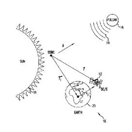
Fig. 1. A schematic view of the subject system for navigation utilizing sources of pulsed celestial radiation (Sheikh, Pines, Wood, Ray and Lovellette, 2007).
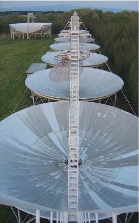
Fig. 2. Photograph of the array at Nasu Radio Interferometer. Eight equally spaced, 20 m diameter, fixed spherical antennas are shown in this figure.
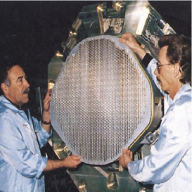
Fig. 3. The AN/APG-77 is a multi-function radar installed on the F-22 Raptor fighter aircraft. The radar is built by Northrop Grumman. The figure come from wiki: http://en.wikipedia.org/wiki/AN/APG-77, accessed Nov 30 2008