Two Approaches to Dislocation Nucleation in the Supported Heteroepitaxial Equilibrium Islanding Phenomenon
Abstract
We study the dislocation formation in 2D nanoscopic islands with two methods, the Molecular Static method and the Phase Field Crystal method. It is found that both methods indicate the same qualitative stages of the nucleation process. The dislocations nucleate at the film-substrate contact point and the energy decreases monotonously when the dislocations are farther away from the island-wetting film contact points than the distance of the highest energy barrier.
1 Introduction
The shape and size of islands resulting from growth processes has been a subject of numerous recent experimental and theoretical studies [1, 2, 3, 4, 5, 6, 7, 8, 9, 11, 13, 14, 15]. In particular, when the growing islands are of nanoscopic size the central issue is the possible spontaneous self-organization of islands into arrays of islands with a narrow size distribution. Such cases offer immediate technological applications in modern nanotechnology. The details of such self-organization processes are poorly understood, however. In particular, there are still uncertainties as to whether the observed shapes and sizes of growing islands in heteroepitaxy correspond to thermodynamic equilibrium state of minimum free energy or they are limited by kinetic effects. In the earlier analytical and numerical studies, in addition to assuming predefined shapes for the islands, the role of dislocation nucleation has not been included.
In the present work we study the dislocation nucleation in two dimensional islands with two methods, the Molecular Static method and the Phase Field Crystal method (PFC) [10]. The appeal of the latter method is that we do not need to initialize the transition path by hand. The way in which the two models reach the timescale of the nucleation process is quite different and our focus is on the qualitative stages of the process and on the agreement between the two approaches.
In the first section on this paper we explain the methods. We use the first, atomistic, model to study the strain relief caused by dislocation formation by minimizing a transition path between the coherent and dislocated states with Nudged Elastic Band (NEB) Method [20]. Then we explore the same process with the PFC method in two dimensions. The nucleation is seen to be qualitatively similar with both approaches.
2 Models and Methods
2.1 Molecular Static Method
We adopt the 2D model used previously in Ref. [19], Interactions between all atoms in the system are described by a modified Lennard-Jones (LJ) pair potential [16] with two parameters, namely the dissociation energy and the atomic equilibrium distance
| (1) |
with a smooth cut-off as in [16]. The indices of the equilibrium distance are , and for the substrate-substrate, adsorbate-adsorbate and adsorbate-substrate interactions, respectively. We model the attraction and lattice mismatch between the two materials by changing the potential depth and the equilibrium interatomic distance between the substrate and the film. The substrate-substrate interaction parameters were set to K and Å corresponding to a Cu substrate [16]. In terms of the lattice mismatch and . A positive mismatch corresponds to compressive strain and negative to tensile strain when the adsorbate island is coherent with the substrate. Analogously we define an interaction parameter which describes the relative difference between the potential minimum depths in the substrate-adsorbate and absorbate-adsorbate interactions. A negative value of corresponds to an effectively attractive and positive to a repulsive substrate. The potential depths can be written as , for the adsorbate-adsorbate and substrate-adsorbate interactions, respectively. We used periodic boundary conditions in the horizontal direction. Two bottom layers of the substrate were held fixed to simulate a semi-infinite substrate while all other layers were free to relax.
2.2 Phase Field Crystal Method
The phase field crystal method (PFC) has been applied in a variety of problems related to non-ideal crystal structures [10]. The method finds the ground state of a given truncated free energy functional without any reference to the instantaneous position of individual atoms. This enables us to find the dislocated ground states even if they were behind kinetic barriers, which would be insurmountable for atomistic simulations. The free energy is
| (2) |
and the parameters and while is the period of the pinning potential to be defined later. The components of the vector We use periodic boundary conditions in the horizontal and mirror boundary conditions in the vertical direction. The function is a pinning potential, which zero, if and otherwise
| (3) |
where The factor ensures that the potential is continuous in the horizontal direction. The amplitude is the pinning potential depth and it plays the same role as the interaction parameter in the Molecular Static method. The difference of the pinning potential and triangular phase periods and is adjusted to give the wanted lattice mismatch. The time step and the grid size The simulation was done on grid. The average density This corresponds to a point in the middle of the constant phase-triangular phase coexistence in the one mode approximation of the phase diagram of Eq. 2. The initial state has an island of half-disc shaped region of triangular phase on the bottom edge of the simulation cell, see Fig.2. This island is surrounded by constant phase. The initial state is evolved according to
| (4) |
where is Gaussian distributed conserved noise [10].
3 Results and Discussion
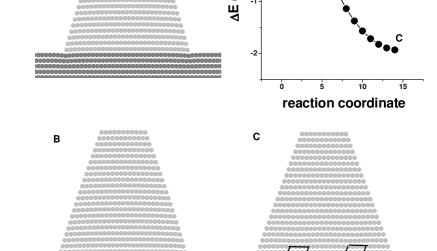
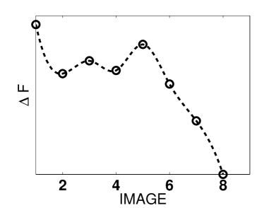
Fig. 1 shows an energy path between coherent and dislocated configurations [19]. The misfit and The initial chain of states is obtained by simple linear interpolation. This chain is minimized with NEB method [20]. The results show an energy barrier for the initial detachment of the dislocation from the island-wetting film contact point. When the distance to the contact is larger than the distance of the highest energy peak, the energy decreases monotonously as the dislocations approach the island center. Finally the defects stop at a finite distance from each other.
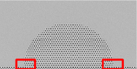
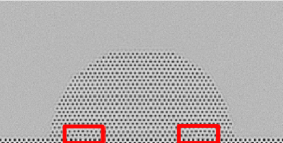
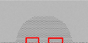
We used the PFC model to make a similar calculation. We used mismatches of and pinning potential depth times the amplitude of the triangular phase. The initial state is the upper half of a disk standing on the simulation cell edge where the pinning potential is effective. For compressive mismatch, the island does not form dislocations but adopts a concave shape with reduced size of the island-wetting film contact area.
In the tensile case dislocations are nucleated symmetrically from both sides of the island base. This is shown in Fig. 2. The defects move towards the island centre. The free energy landscape is given in arbitrary units as a function of the image number. It shows the combined effect of dislocation nucleation and facet formation. These effects could be studied separately by starting from dislocated or faceted initial configuration. The general shape of the curve in Fig. 2 is similar to that of Fig. 1.
4 Conclusions
We have studied dislocation nucleation in 2D strained heteroepitaxial nanoislands. We have employed both an atomistic model and phase field crystal method. The results are qualitatively consistent with each other. The dislocations nucleate near the island-wetting film contact under tensile strain. After an initial energy barrier the dislocation detaches from the contact point and moves to the middle of the island. During the move the energy is lowered gradually. The island shapes in the tensile case were observed to be more faceted than in the compressive case.
5 Acknowledgements
J. Jalkanen has also been supported by the Foundation Vilho, Yrjö ja Kalle Väisälän rahasto of Finnish Academy of Science and Letters, a joint fund under EU STREP 016447 MagDot and NSF (DMR-0502737) and the Academy of Finland through its Center of Excellence Grant (COMP).
References
References
- [1] P. Politi, G. Grenet, A. Marty, A. Ponchet, and J. Villain, 2000 Phys. Reports 324, 271
- [2] I. Daruka, J. Tersoff, and A.-L. Bara’bási 1999 Phys. Rev. Lett. 82, 2753
- [3] I. Daruka and J. Tersoff 2002 Phys. Rev. B 66, 132104
- [4] M.Moll, M. Scheffler and E. Pehlke 1998 Phys. Rev. B, 58, 4566
- [5] L.G. Wang, P. Kratzer, N. Moll, and M. Scheffler 2000 Phys. Rev. B 62, 1897
- [6] L.G. Wang, P. Kratzer, M. Scheffler and N. Moll 1999 Phys. Rev. Lett. 82, 4042
- [7] C. Ratsch and A. Zangwill 1993 Surf. Sci. 293, 123
- [8] H.T. Johnson and L.B. Freund 1997 J. Appl. Phys. 81, 6081
- [9] B.J. Spencer and J. Tersoff 2001 Phys. Rev. B 63, 205424
- [10] K. Elder and M. Grant 2004 Phys. Rev. E 70, 051605
- [11] J. Tersoff and F.K. LeGoues 1994 Phys. Rev. Lett. 72, 3570
- [12] E. Hahn, E. Kampshoff, N. Wälchli and K. Kern 1995 Phys. Rev. Lett. 74, 1803
- [13] R. A. Budiman and H.E. Ruda 2002 J. Appl. Phys. 88, 4586
- [14] A. Ponchet, A. Le Corre, H. L’Haridon, B. Lambert, S. Salan, D. Alquier, D. Lacombe and L. Durand 1998 Appl. Surf. Sci. 123, 751
- [15] H. Uemura, M. Uwaha and Y. Saito 2002 J. Phys. Soc. Japan 71, 1296
- [16] S. Zhen and G. J. Davies 1983 Phys. Stat. Sol. A 78, 595
- [17] O. Trushin, E. Granato, S.-C. Ying, P. Salo and T. Ala-Nissila, 2002 Phys. Stat. Sol. B, 232,100
- [18] O. Trushin, E. Granato, S.-C. Ying, P. Salo and T. Ala-Nissila 2003 Phys. Rev. B 65, 241408(R) ; 2003 Phys. Rev. B 68, 155413
- [19] J. Jalkanen, O. Trushin, E. Granato, S.C Ying, T. Ala-Nissila 2005 Phys. Rev. B 72, 081403 (R)
- [20] H. Jònsson, G. Mills, and K. W. Jacobsen 1998 Classical and Quantum Dynamics in Condensed Phase Simulations edB. J. Berne et al. (Singapore: World Scientific)