Independent magnetization behavior of a ferromagnetic
metal/semiconductor hybrid system
Abstract
We report the discovery of an effect where two ferromagnetic materials, one semiconductor ((Ga,Mn)As) and one metal (permalloy), can be directly deposited on each other and still switch their magnetization independently. We use this independent magnetization behavior to create various resistance states dependent on the magnetization direction of the individual layers. At zero magnetic field a two layer device can reach up to four non-volatile resistance states.
pacs:
75.50.Pp, 75.30.Gw, 75.70.Cn, 85.75.-dDevices whose functioning is based on the relative magnetization state of two controllable magnetic elements, such as GMR (giant magneto resistance) BAIBICH1988 BINASCH1989 based read heads Theis2003 and TMR (tunnel magneto resistance) JULLIERE1975 based MRAM Akerman2005 are crucial to the modern information technology industry. So far, all such devices have been comprised of at least three layers: the two magnetic layers and a spacer layer to break the direct coupling between them and allow them to reorientate their relative magnetization. In this letter we show that, unlike the case of two ferromagnetic (FM) metals, the bringing together of a FM metal with a FM semiconductor (SC) can allow the layers to remain magnetically independent and thus permit the fabrication of devices without the need of a non magnetic interlayer. We demonstrate a first such device, which because of the strong anisotropies in the FM semiconductor layer has not only two, but up to four stable resistance states in the absence of a magnetic field.
To prepare these structures, a 100 nm (Ga,Mn)As layer is grown by low-temperature molecular beam epitaxy on a GaAs buffer and substrate. Subsequently, without breaking the vacuum, the sample is transferred to a UHV magnetron sputtering chamber, and a permalloy (Ni80Fe20) film with a thickness of 7 nm (and in some cases a 3 nm thick magnesium oxide (MgO) capping film) is deposited on top of the (Ga,Mn)As layer (fig. 1a). Using optical lithography and chemically assisted ion beam etching (CAIBE), this layer stack is patterned into a 40 m wide Hall bar oriented along the (Ga,Mn)As [010] crystal direction. Ti/Au contacts are established through metal evaporation and lift-off.
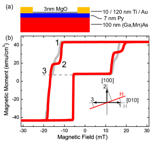
For an initial study of the layer system, we include an MgO film on top of the permalloy layer to prevent the permalloy from naturally oxidizing in air. Without a cap layer the natural oxide consisting of NiO on an Fe oxide layer Fitzsimmons2006 produces an exchange bias coupling MEIKLEJOHN1956 with a magnetic field dependent anisotropy Stiles1999 Nogues1999 below its Néel temperature HAGEDORN1967 which unduly complicates the layer characterization. We find that sputtering MgO on Py creates a well-defined uniform antiferromagnetic layer which couples antiferromagnetically to the Py film. Cooling the Py/MgO system from above its Néel temperature to 4.2 K in an applied magnetic field results in a fixed exchange bias coupling which is not affected by further magnetic field sweeps. This exchange bias coupling induces a stable unidirectional anisotropy in the Py film. Both, the unidirectional anisotropy of Py and the principally biaxial in-plane easy axes of (Ga,Mn)As Sawicki2004 , can be observed in direct magnetization measurements. Figure 1b shows two magnetization hysteresis loops of a layer system composed of (Ga,Mn)As and Py/MgO measured by SQUID (superconducting quantum interference device). In this experiment a magnetic field of +300 mT has been applied during the cooling procedure from 150 to 4.2 K along the field sweep direction. As a result, the magnetization contribution of the Py/MgO system is shifted along the field axis generally in the opposite (’negative’) direction of the cooling field. In addition to the Py/MgO contribution one can see the very characteristic double-step reversal process of the (Ga,Mn)As layer. This layer is not exchange biased, and its behavior is symmetric around the origin. These two statements can be validated from a detailed analysis of the hysteresis curves as follows.
In Fig. 1b, the red curve was obtained by sweeping the field along with respect to the [010] (Ga,Mn)As crystal direction. The measurement begins at +300 mT, with the magnetization of both layers pointing along the field direction. As the field is reduced the Py magnetization continues to point in the direction, whereas the (Ga,Mn)As magnetization gradually relaxes to the [010] easy axis (see inset in fig. 1b). In our configuration, the SQUID measures only the projection of the total moment onto the field axis, therefore the (Ga,Mn)As magnetization rotation towards the [010] axis changes the value to . This rotation occurs at fields greater than 30 mT and is not visible in the figure. As the field is lowered through zero, at -12 mT a domain wall nucleates and propagates through the (Ga,Mn)As layer, causing a switch in the direction of its magnetization to the [100] crystal direction. At -16 mT a second (Ga,Mn)As domain wall nucleates and propagates, completing the reversal. Right after this second (Ga,Mn)As event, the Py changes its magnetization (at -17 mT) from to the direction. For the back sweep of the magnetic field, because it is exchange biased, the Py layer reverses its magnetization before zero field at -6 mT. is hysteretically symmetric and reverses its direction at positive fields through the same double-step switching process as before. This behavior is characteristic of the two layers responding independently to the applied magnetic field.
After warming the sample to 150 K, and recooling with a magnetic field along , the second hysteresis loop with a field sweep along the (Ga,Mn)As [010] easy axis is measured (fig. 1b, gray curve). Due to its unidirectional anisotropy, which is set by the exchange bias and is once again oriented along the measurement axis, the permalloy shows a behavior identical to the direction measurement. Because the sweep direction is now along a (Ga,Mn)As easy axis, the projection onto the field axis after the first switching event is almost zero, and the two switching events occur at almost the same field with an intermediate state having a value of half the (Ga,Mn)As total moment. This again confirms the independent character of the two layers.
For a more detailed analysis of this independent switching behavior, transport measurements are performed at 4.2 K in a magnetocryostat fitted with three orthogonal Helmholtz coils which can produce a magnetic field of up to 300 mT in any direction. Results discussed here are for longitudinal resistance () measurements. The change in in response to an external magnetic field can be ascribed to the anisotropic magnetoresistance (AMR) MCGUIRE1975 Jan57 , which shows a typical -dependence where denotes the angle between magnetization and current. In (Ga,Mn)As, the resistance perpendicular to the magnetization is larger than the resistance parallel to the magnetization Baxter2002 while the opposite is true for permalloy.
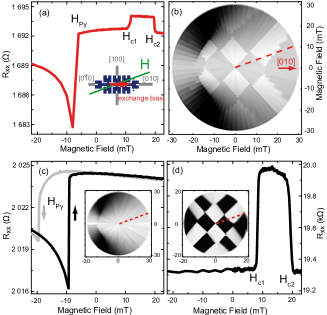
Figure 2a presents a magnetoresistance curve along for the hybrid system of fig. 1 (100 nm (Ga,Mn)As, 7 nm Py and 3 nm MgO), obtained after cooling the sample in a 300 mT field oriented along , and where one can identify the properties of the individual layers. The reorientation of starts at negative fields and switches to the preferred axis at mT. The two (Ga,Mn)As switching fields and are at mT and mT, respectively. To outline the full anisotropy, the positive field half of such magnetoresistance curves for multiple directions (here every ) are merged into a gray scale resistance polar plot (RPP) Pappert2007a with the magnetic field H along the radius as shown in fig. 2b. The gray scale encodes the resistance values, where black denotes minimum and white maximum resistance. The single curve from fig. 2a is along the dashed line in fig. 2b. In order to more clearly understand the anisotropy pattern of this hybrid system, we now present data on characteristic individual (Ga,Mn)As and Py/MgO layers.
Figure 2c shows AMR of a 7 nm thick Py layer capped by a 3 nm thick MgO layer. Its primary anisotropy is unidirectional due to exchange bias of mT. After a field cooling procedure the unidirectional anisotropy points along the Hall bar which is defined as the direction in this case. At high negative magnetic fields along the Py magnetization is antiparallel to the direction. As the field is brought back towards zero (black curve) rotates towards the unidirectional easy direction. Since this is more than from the original direction, this rotation initially increases , and this leads to a decrease in resistance. At mT switches abruptly to the direction before having reached the point where and I are perpendicular to each other. At zero magnetic field , and we observe a high resistance state. As the magnetic field is increased further gradually rotates to the direction of the external magnetic field. A back trace from high positive field to negative field for the direction is also shown in fig. 2c (light gray). For a pure unidirectional anisotropy one expects two identical MR-curves. The deviations of the two directions comes from an additional biaxial anisotropy in the Py/MgO system Michel1998 with a strength of approximately 7 mT. The inset shows a set of magnetic field scans along many angles compiled into a RPP.
Figure 2d presents a (Ga,Mn)As magnetoresistance curve along . At -20 mT the magnetization has already relaxed to the (Ga,Mn)As easy axis. A first abrupt resistance change at the field happens due to a reorientation of towards the [100] (Ga,Mn)As easy axis. A second reorientation of towards [010] at completes the magnetization reversal. Again, a RPP is presented in the inset.
By comparing to the RPP of the individual layers, it is clear to see that in the RPP of the hybrid system the characteristic square pattern of the (Ga,Mn)As anisotropies is superimposed on the pattern from the Py layer. This behavior again demonstrates the independent switching of the two magnetic layers in the sample.
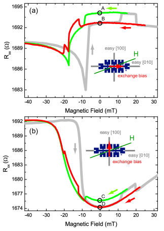
As in GMR and TMR devices, these two independent magnetic layers allow us to set up two non-volatile resistance states. We demonstrate this with minor loops, sweeping the magnetic field from negative saturation to a positive field value and back to negative saturation. Figure 3a shows two minor loops along and a reference full trace (light gray) as described in fig. 2a. The unidirectional anisotropy in the Py layer is now set by field cooling along the (Ga,Mn)As [010] crystal direction. Each minor loop is of course identical to the reference curve until their reversal point. Therefore only the back sweeps of the minor loops are shown. Coming from negative saturation the magnetization states of both layers are antiparallel at zero field (fig. 3a). Sweeping the magnetic field further, the (Ga,Mn)As magnetization reorients at mT to the [100] crystal direction through a domain wall nucleation and propagation. On stopping the field at mT and sweeping it back to zero, points perpendicular to . This corresponds to a high resistance state associated with an angle of between I and and an angle of between I and . Repeating the whole procedure and sweeping the magnetic field to mT instead of mT, (Ga,Mn)As completes the magnetization reversal through a second domain wall nucleation and propagation. Back at zero field the magnetization states of the Py and (Ga,Mn)As layers are aligned parallel to each other. This corresponds to a high resistance state for permalloy and a low resistance state for (Ga,Mn)As.
Figure 3b shows a similar configuration except the unidirectional anisotropy is reset by warming the sample to 150 K and cooling it with an appropriate applied magnetic field, to point along [100] instead of [010]. The magnetic field is again swept in the direction. At zero field the permalloy magnetization is always parallel to [100], which is equal to a permalloy low resistance state (). The behavior of the (Ga,Mn)As layer is identical to the minor loop described in fig. 3a. There are again two different resistance states which can be ascribed to the AMR effect of the individual layers. The minimum in fig. 3b belongs to along [100] and either along [010] or (labeled D). At C both magnetization states are pointing parallel to [100]. This corresponds to a high (Ga,Mn)As resistance and a low permalloy resistance value.
To confirm that the magnetic independence of the two layers does not originate from an electrical decoupling at the interface, we determined the interface resistance in samples where current is passed through the interface. The resulting contact resistance is less than , which is comparable to high quality ohmic contacts on (Ga,Mn)As. Nevertheless, we suggest that the most plausible explanation for the lack of magnetic coupling between the layers stems from the fact that the magnetism in the Py layer is mediated by free electrons whereas in the (Ga,Mn)As it is hole mediated. We note that this hypothesis is not inconsistent with the observation that charge transport takes place freely through the interface. For a charge current to flow between an n-type and a p-type layer, a mechanism is only required to provide charge conversion at the interface. In contrast, the transport of magnetic order through the interface has much stricter requirements, necessitating the two type of carriers to coherently exchange spin information.
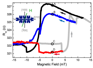
Having established the characteristics of the two independent layers, we now show how it can lead to a multi-value memory element. We proceed with a new sample; a layer stack as in fig. 1a, but the MgO left out in favor of a natural oxide on the Py layer. This allows the use of a magnetic field to modify Stiles1999 the exchange bias coupling direction, allowing measurements for various Py magnetization directions at zero field, while remaining at constant temperature. Figure 4 shows three minor loops and a full magnetoresistance curve (light gray) of a hybrid system consisting of a 70 nm (Ga,Mn)As and a 7 nm Py layer. Again only the back sweeps for the minor loops are shown. The sample is cooled without an applied magnetic field. The current path is patterned along a (Ga,Mn)as easy axis and the magnetic field sweep direction is .
The field sweep starts at -300 mT, and at 0 mT (labeled C in fig. 4) the total resistance has a lower intermediate state, where both magnetization states point parallel towards the (Ga,Mn)As which is associated with a high resistance state for (Ga,Mn)As and a low resistance state for Py. The first abrupt resistance change at 3.5 mT corresponds to a reorientation of towards the other (Ga,Mn)As easy axis. Sweeping the field from 4 mT back to zero one reaches the lowest resistance state of the hybrid system (labeled D) where both individual layers are in their low resistance state. Lowering the magnetic field even more the (Ga,Mn)As layer switches back to the direction. By sweeping the magnetic field past +9 mT, we make use of the field rotation effect to realign the exchange bias field between the Py and the natural oxide layer and therefore also realign the induced anisotropy in the Py layer. Due to this reorientation the Py has a different magnetization state for zero field. This leads to two additional stable states (A,B) in the figure corresponding to pointing along [010] (B) and [100] (A). The magnetization of the Py layer for these cases is almost parallel to the current direction. These four states are comparable to those we observed earlier with a thermal cycle (fig. 3). This time however, all four states are achieved without warming the sample, simply by proper manipulation of the levels using a magnetic field.
In conclusion we have shown that independent magnetic behavior can be obtained for magnetic layers of (Ga,Mn)As and permalloy in direct contact without the need for a nonmagnetic interlayer. The independence of the layers was confirmed both by transport observations, and direct magnetization measurements using SQUID. We also made use of this functionality to demonstrate a two layer hybrid multi-valued memory element with four non-volatile configurations at zero magnetic field.
Acknowledgements.
The authors thank M. Sawicki for useful discussions and V. Hock and T. Borzenko for help in sample fabrication. We acknowledge financial support the EU (NANOSPIN FP6-IST-015728).References
- 1 Baibich, M. N., Broto, J. M., Fert, A., Vandau, F. N., Petroff, F., Eitenne, P., Creuzet, G., Friederich, A., and Chazelas, J. Phys. Rev. Lett. 61(21), 2472–2475 November (1988).
- 2 Binasch, G., Grünberg, P., Saurenbach, F., and Zinn, W. Phys. Rev. B 39(7), 4828–4830 March (1989).
- 3 Theis, T. N. and Horn, P. M. Physics Today 56(7), 44–49 July (2003).
- 4 Julliere, M. Physics Letters A 54(3), 225–226 (1975).
- 5 Åkerman, J. Science 308(5721), 508–510 April (2005).
- 6 Fitzsimmons, M. R., Silva, T. J., and Crawford, T. M. Phys. Rev. B 73(1), 014420 January (2006).
- 7 Meiklejohn, W. H. and Bean, C. P. Phys. Rev. Lett. 102(5), 1413–1414 (1956).
- 8 Stiles, M. D. and McMichael, R. D. Physical Review B 59(5), 3722–3733 February (1999).
- 9 Nogues, J. and Schuller, I. K. J. Mag. Mag. Mat. 192(2), 203–232 February (1999).
- 10 Hagedorn, F. B. J. App.l Phys. 38(9), 3641–& (1967).
- 11 Sawicki, M., Matsukura, F., Idziaszek, A., Dietl, T., Schott, G. M., Ruester, C., Gould, C., Karczewski, G., Schmidt, G., and Molenkamp, L. W. Phys. Rev. B 70(24), 245325 December (2004).
- 12 McGuire, T. R. and Potter, R. I. IEEE Trans. Magn. 11(4), 1018–1038 (1975).
- 13 Jan, J. P. (Eds: F. Seitz, D. Turnbull). Academic Press Inc., New York, (1957).
- 14 Baxter, D. V., Ruzmetov, D., Scherschligt, J., Sasaki, Y., Liu, X., Furdyna, J. K., and Mielke, C. H. Phys. Rev. B 65(21), 212407 June (2002).
- 15 Pappert, K., Hümpfner, S., Wenisch, J., Brunner, K., Gould, C., Schmidt, G., and Molenkamp, L. W. Appl. Phys. Lett. 90(6), 062109 February (2007).
- 16 Michel, R. P., Chaiken, A., Wang, C. T., and Johnson, L. E. Physical Review B 58(13), 8566–8573 October (1998).