Effect of Nonlocal Spin-Transfer Torque on Current-Induced Magnetization Dynamics
Abstract
Using the self-consistent model, we present nonlocal spin-transfer effects caused by the feedback between inhomogeneous magnetization and spin-transfer torque on the current-induced magnetization dynamics in nanomagnets. The nonlocal effects can substantially improve the coherence time of precession in nanomagnets and thus reduce the linewidth of power spectrum. This narrow linewidth results from the nonlinear damping of spin-waves due to the nonlocal spin torque which is inherent and thus should be considered in future experiments.
pacs:
85.75.-d, 72.25.Ba, 75.40.Mg, 75.47.DeA spin-polarized current exerts a torque to a ferromagnet (FM) by transferring the spin-angular momentum, i.e. spin-transfer torque Slon (STT). STT generates a new class of magnetization (M) dynamics in spin-valve structures Myer ; Kiselev , potentially useful for applications in magnetic nonvolatile memories and microwave oscillators.
In layered structures where the current flows perpendicular to the plane, the direction and magnitude of STT at a point r is decided by the spin accumulation and associated spin current at the same point r. Initial theories Slon assumed that the dependence of on M is local and thus essentially fixed by the local M at the same point r. However, its dependence on M is inherently nonlocal because of the 3-dimensional (3D) spin diffusion Polianski ; Stiles ; Brataas . In other words, when the conduction electron arrives at a point r on the FMnormal metal (NM) interface, the reflected (transmitted) electron takes the spin direction anti-parallel (parallel) to the local M at the point r, diffuses along the interface, and then transfers its spin-angular momentum to another local M at a far away point from the r. That is, at a point r is affected by all local M’s at other points. The local assumption becomes really invalid when M is inhomogeneous. Note that micromagnetic Miltat ; LeeNat and time-resolved imaging studies Acremann have revealed excitations of incoherent spin-waves and thus inhomogeneous M due to STT. In this situation, the effect of on M (=STT) and the nonlocal effect of M on the should be treated on an equal footing. The conventional treatments, which ignore the latter part, actually deal with only half of the relevant parts. Therefore, the self-consistent feedback between inhomogenous M and STT through the nonlocal effect should be considered.
The STT caused by the nonlocal effect can be named nonlocal spin-transfer torque (NLST) since it allows a single FM with inhomogeneous M to exert spin-transfer effects on itself. Despite efforts to investigate NLST, the understanding of the M dynamics affected by NLST remains elusive especially for the spin-valve structure which is important from the viewpoints of fundamental physics and applications. Previous theoretical studies on NLST Polianski ; Stiles ; Brataas have addressed the phenomenon in the perturbative regime of small spin-wave amplitudes and thus could not investigate the dynamic modes for the current exceeding the threshold for the onset of magnetic excitation. Previous numerical studies Adam lacked the exact calculation of 3D dynamic motion of and focused only on the single FM.
In this Letter, we have directly calculated 3D dynamic motion of self-consistently coupled with the M dynamics, which allows us to apply the model to both single FM and spin-valve structures. This self-consistent treatment is essential to correctly describe unique spin-wave modes caused by NLST and explains two important experimental results: spin-wave excitations in a single FM Ozyilmaz and narrower linewidths in spin-valves than are expected within the assumption of homogeneous M Sankey .
The equations of motion of M (Eq. (1)) and (Eq. (2)) Polianski ; Stiles ; Brataas are self-consistently solved for FM and NM.
| (2) |
Here is the unit vector of M, is the gyromagnetic ratio of FM (NM), is the effective field including the magnetostatic, exchange, external (), current-induced Oersted, and thermal fluctuation fields, is the intrinsic damping constant, is the saturation magnetization, is the thickness of FM, is the spin current, is the diffusion coefficient, is the spin-flip scattering time, and is the spin-diffusion length. The change of charge and spin current and at the interface of FMNM are related to the potential drop over the interface as Circuit
| (3) | |||||
| (4) | |||||
where is the electric potential, is the potential drop over the interface, (s= or ) is the spin-dependent conductivity, is the bulk (interface) spin asymmetry, is the mixing conductivity. A small is disregarded Zwierzycki . At the interface of FMNM, and are continuous under the condition of in FM. and are related through the Eqs. (2)-(4), and the spin-version of the Ohm’s law with the boundary conditions of and at the far-right (-left) end of the NM electrodes.
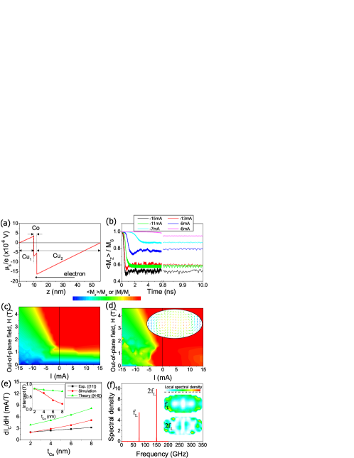
To validate the self-consistent model, we first carried out simulations for the single FM, CuCo()Cu (all in nm) where varies from to , and compared modeling results to the experimental ones in the Ref. Ozyilmaz . Since this structure has no second FM, the conventional LLG-Slonczewski equation is not applicable. Asymmetric Cu leads provide asymmetric at each side of the Co layer (Fig. 1(a)). at interfaces () is negative when the electron flows from the thick to thin Cu layers, corresponding to a negative current. This negative provides negative NLST. Fig. 1(b) shows the time evolution of averaged out-of-plane component of M () at various negative currents when the out-of-plane field is . M initially saturates along the out-of-plane direction, but cannot keep the saturation state at negatively large currents even when is larger than the out-of-plane demagnetization field () (Fig. 1(c)). When the current is turned on, a tiny in-plane component of M is developed especially at the long edges where the Oersted field is the largest. Interplay between this inhomogeneous M and negative NLST excites spin-waves, resulting in the rapid decrease of within a few nanoseconds.
As in the experiment Ozyilmaz , we observed current-induced excitations only at negative currents. The normalized modulus of the magnetic moment is much smaller than at those bias conditions (Fig. 1(d)), indicating excitation of large amplitude incoherent spin-waves. Inset of Fig. 1(d) shows a snapshot of domain pattern at and . Local M’s at edges are mostly in the plane whereas those near the center of cell are in vortex-like states caused by negative NLST which prefers non-collinear configuration of local M’s. This inhomogeneous M results in the reduction of the average spin accumulation in the NM and thus the reduction of resistance of the stack (not shown).
When , the critical current for excitations linearly depends on (Fig. 1(c) and (d)). As shown in Fig. 1(e), numerical results of the slope () are in better agreement with the experimental ones than the theoretical ones (for the theoretical , see Eq. (10) in the Ref. Polianski ). In the experiment Ozyilmaz , the intercept of extrapolated boundary at is nearly zero for the sample with , whereas the theoretical intercept is about for all thicknesses (inset of Fig. 1(e)). For , the numerical intercept is and again in better agreement with the experimental one. We attribute these better agreements to the fact that the self-consistent model more realistically takes into account the influence of the shape and finite size of nano-pillar on the spin-wave mode.
Fig. 1(f) and insets show eigenmode analysis for the M dynamics at and , corresponding to a periodic oscillation of . As shown in Fig. 1(b), however, the oscillation is in general nonperiodic for most negative currents due to highly nonlinear coupling among local M’s through the NLST. A rule of the bias condition for a periodic oscillation may exist but we could not find it because of a fixed step size of and in our simulations. At this bias condition, the power spectrum shows two peaks at and where . The eigenmode images (insets) show that the precession region with a higher power is localized at edges. Note that these eigenmodes are unique features of the NLST and not expected in the field-driven excitation McMichael .
This result demonstrates one crucial implication of the NLST, namely, destabilization effect of negative NLST on local M’s. Via the spin diffusion, the electrons backscattered from the FM destabilize local M’s whereas the electrons transmitted through the FM stabilize. The two effects always exist simultaneously but one dominates the other because the NM electrodes and thus are not symmetric. Since the sign of is reversed by changing the current polarity, the stabilizing effect is expected for a positive current, i.e. positive NLST. In the single FM excitation, we observed almost macrospin behaviors for positive NLST. In a spin-valve, however, different types of spin-wave modes are expected for positive NLST because the local STT is nonzero and thus generates incoherent spin-waves LeeNat .
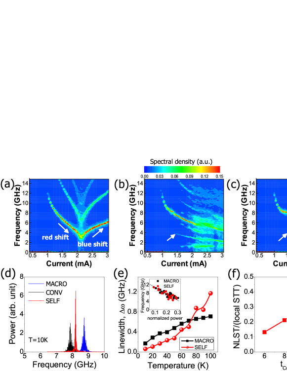
In the second study, we applied the self-consistent model to a spin-valve structure, Cu(80)Py(20)Cu(6)Py(2)Cu(2) (Py=Permalloy) experimentally studied by Sankey et al. Sankey . They reported a surprising result that the current-induced dynamic modes can generate narrower linewidths at low temperatures than those expected within the macrospin assumption. To investigate the origin of this experimental finding, we performed simulations with three different approaches: i) macrospin model (MACRO), ii) conventional micromagnetic model without considering NLST (CONV), and iii) self-consistent model (SELF). Fig. 2(a), (b) and (c) show contours of spectral density of as a function of at when the effective field of is applied along the in-plane easy axis . The positive current corresponds to the electron-flow from Cu(2) to Cu(6), and thus positive NLST. MACRO shows the well-known red- and blue-shift depending on (Fig. 2(a)). CONV shows only red-shift up to a critical current (, Fig. 2(b)). When , M dynamics in CONV becomes complicated due to excitations of incoherent spin-waves. As indicated by an arrow, we observed secondary peaks with about half the frequency of main peaks, corresponding to the precession of end domains LeeNat . In SELF, we observed similar secondary peaks indicating non-single domain state, but much clearer peak structures than CONV up to about which is larger than (Fig. 2(c)). It indicates that the positive NLST provides a more periodic oscillation than that obtained in CONV.
Fig. 2(d) shows power spectra obtained in the three models. At a low temperature (), SELF shows the narrowest linewidth whereas CONV produces the broadest one due to excitations of incoherent spin-waves. We calculated the dependence of linewidth from lorentzian fits (Fig. 2(e)). At low temperatures, SELF provides narrower linewidths than MACRO, consistent with the experimental observation Sankey . Therefore, the positive NLST indeed results in a substantial improvement of the coherence time of precession although M is not in the single domain state. It indicates that it is possible to reduce the linewidth by properly controlling the NLST. In MACRO, the linewidth monotonously increases with . On the other hand, in SELF, the linewidth linearly depends on for and more rapidly increases at higher temperatures.
The narrower linewidths in SELF are caused by two nonlinear effects of the positive NLST: an increase of the effective exchange stiffness in short range and an increase of the damping of incoherent spin-waves in long range. As a result, the positive NLST provides an additional nonlinear spin-wave damping. For a spin-torque nano-oscillator, the linewidth in the low-temperature limit is given by Slavin
| (5) |
where is the nonlinear frequency shift coefficient obtained from , is the ferromagnetic resonance frequency at , is the normalized power, is the effective nonlinear damping, is a phenomenological coefficient characterizing the nonlinear positive damping, and is the critical current for the magnetic excitation (for details of other parameters, see Ref. Slavin ).
Eq. (5) predicts two important consequences of the nonlinearity. First, the linewidth of an auto-oscillator with a nonlinear frequency shift (i.e. ) increases by the factor from that of a linear oscillator (i.e. ). Second, the linewidth of a nonlinear oscillator decreases with increasing the nonlinearity of damping . It is because the linewidth is determined by nonlinear properties of the system where the normal linear damping is compensated by local STT. In this case, an increase of the nonlinearity of damping can lead to a decrease of the linewidth, known as the noise suppression due to nonlinear feedback RMP .
Inset of Fig. 2(e) shows that is nonzero and almost identical for the two models. Thus, the linewidth is wider than that expected in a linear oscillator. Using Eq. (5), we fit the values of from the calculated linewidths at and obtained in MACRO and in SELF. The fit value in SELF is consistent with the assumed values Slavin to explain experimental observations. Note that the nonlinear theory referred here does not take into account the spin transport and the value has been used as a fitting parameter without justification of its origin. In contrast, our self-consistent treatment shows that the large is mainly caused by NLST. Thus, we conclude that the nonlinear spin-wave damping due to NLST is responsible for narrower linewidths in SELF at low temperatures. When is too high, the thermal random force overcomes the nonlocal effect due to positive NLST and thus the linewidth abruptly increases. For the opposite current polarity (i.e. negative NLST), we observed an increase of the linewidth (not shown).
Finally, we note that the magnitude of NLST is easily controlled by modifying the asymmetry of layer structure like the conventional local STT. The effect of NLST on the current-induced M dynamics is determined by the ratio of NLST to local STT. Fig. 2(f) shows the ratio at the parallel magnetic configuration as a function of the thickness of Cu spacer for the spin-valve structure studied here. The ratio is about at which is the case of the Ref. Sankey . Note that the effect of NLST on the current-induced M dynamics is considerable although the ratio is only . Furthermore, this ratio increases with increasing as shown in Fig. 2(f). Therefore, NLST should be considered in designing and interpreting future experiments.
We thank B. Dieny, A. Vedyayev, M. D. Stiles, A. Brataas, A. Kent, J. Z. Sun, I. N. Krivorotov, A. N. Slavin, J. -V. Kim, S. Zhang and H. -W. Lee for fruitful discussions. This work was supported by KRF (MOEHRD) (KRF-2006-311-D00102), KOSEF through the NRL Program (No. M10600000198-06J0000-19810), KISTI under the Strategic Supercomputing Support Program.
References
- (1) J. C. Slonczewski, J. Magn. Magn. Mater. 159, L1 (1996); L. Berger, Phys. Rev. B 54, 9353 (1996).
- (2) E. B. Myers et al., Science 285, 867 (1999).
- (3) S. I. Kiselev et al., Nature (London) 425, 380 (2003).
- (4) M. L. Polianski and P. W. Brouwer, Phys. Rev. Lett. 92, 026602 (2004).
- (5) M. D. Stiles, J. Xiao, and A. Zangwill, Phys. Rev. B 69, 054408 (2004).
- (6) A. Brataas, Y. Tserkovnyak, and G. E. W. Bauer, Phys. Rev. B 73, 014408 (2006).
- (7) J. Miltat, G. Albuquerque, A. Thiaville, and C. Vouille, J. Appl. Phys. 89, 6982 (2001); K.-J. Lee and B. Dieny, Appl. Phys. Lett. 88, 132506 (2006).
- (8) K.-J. Lee et al., Nat. Mater. 3, 877 (2004).
- (9) Y. Acremann et al., Phys. Rev. Lett. 96, 217202 (2006); J. P. Strachan et al., Phys. Rev. Lett. 100, 247201 (2008).
- (10) S. Adam, M. L. Polianski, and P. W. Brouwer, Phys. Rev. B 73, 024425 (2006); M. A. Hoefer, T. J. Silva, and M. D. Stiles, Phys. Rev. B 77, 144401 (2008).
- (11) B. Özyilmaz et al., Phys. Rev. Lett. 93, 176604 (2004).
- (12) J. C. Sankey et al., Phys. Rev. B 72, 224427 (2005).
- (13) A. Brataas, Y. V. Nazarov, G. E. W. Bauer, Phys. Rev. Lett. 84, 2481 (2000).
- (14) M. Zwierzycki et al., Phys. Rev. B 71, 064420 (2005).
- (15) J. Bass and W. P. Pratt Jr., J. Magn. Magn. Mater. 200, 274 (1999).
- (16) R. D. McMichael and M. D. Stiles, J. Appl. Phys. 97, 10J901 (2005).
- (17) I. N. Krivorotov et al., Science 307, 228 (2005).
- (18) A. N. Slavin and K. Pavel, IEEE Trans. Magn. 41, 1264 (2005); J. -V. Kim, V. Tiberkevich, and A. N. Slavin, Phys. Rev. Lett. 100, 017207 (2008); J. -V. Kim et al., Phys. Rev. Lett. 100, 167201 (2008).
- (19) J. Bechhoefer, Rev. Mod. Phys. 77, 783 (2005).