Fiber lasers generating radially and azimuthally polarized light
Abstract
A simple, robust, and efficient method to produce either radially or azimuthally polarized output beam from a fiber laser is presented. Experimental results reveal that polarization purity of 90% or better can be obtained.
pacs:
42.55.Wd, fiber lasers, 42.25.Ja PolarizationRadially and azimuthally polarized laser beams have unique properties and symmetries. For example, radially polarized light under tight focusing conditions, produces strong longitudinal electric field at the focus, while the azimuthally polarized light produces strong longitudinal magnetic field Focus1 . Such properties are advantageous for various applications including microscopy Microscopy , material processing LaserProssessing ; Drill , trapping and acceleration of particles Trap1 ; Trap2 and laser light amplifications GalinaAmp . Moreover, since the cross-section intensity distribution of radially and azimuthally polarized light have a doughnut shape, their peak intensity is significantly lower than that of a Gaussian light, so that non-linear and damage effects are reduced. Also, radially and azimuthally polarized light can propagate inside a non polarization maintaining multi-mode fiber with much less effects from birefringence than linearly polarized light BandGap ; Grosjean1 ; Volpe ; Grosjean2 .
Over the years, many methods have been developed in order to generate radially and azimuthally polarized light with lasers. With solid state lasers they involved phase elements Oron , computer generated holograms ComputerHologram and spatially variable retarder SVR2008 . While in fiber lasers they involved an intra-cavity axicon ShirakwaRadialFiber1 and an intra-cavity dual conical element ShirakwaRadialFiber2 to produce only radially polarized light; unfortunately, these methods are highly sensitive and have low polarization purity.
In this letter, we present a highly efficient method for obtaining either radial or azimuthal polarization directly from a fiber laser. This method involves the introduction of strong losses to an unwanted polarization inside the fiber laser cavity by means of a spatially variable retarder GalinaSVR and a thin film polarizer. While this method has been successfully demonstrated with solid-state lasers SVR2008 , it was not clear whether it would be effective with fiber lasers that have relatively strong nonlinearities, high gain, and birefringence. Especially, with fiber lasers which include multimode fibers and are non-polarization maintaining fibers.
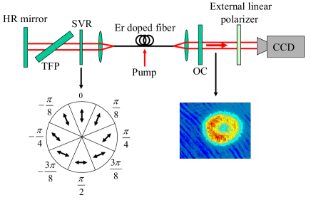
The basic configuration for generating radially and azimuthally polarized light in a fiber laser, is schematically presented in Fig. 1. It includes ten meter long non-polarization maintaining Erbium-doped fiber. The fiber can support few modes and has a numerical aperture of 0.07, core diameter of and cladding diameter of . The fiber is side pumped from both directions with two multi-mode diode lasers of each. The two fiber ends are cleaved at to suppress any reflection back into the fiber. The light emerging from one end of the fiber is collimated and propagates toward a 4% reflecting output coupler (OC), while the light emerging from the other end is collimated and propagates toward the highly reflecting (HR) back mirror. A spatially variable retarder (SVR) GalinaSVR and a thin film polarizer (TFP) are inserted between the collimating lens and the back mirror. The TFP reflects the S polarized light out of the laser so only the P polarized light is reflected back towards the SVR. The SVR is comprised of eight sectors each having retardation in different orientations, where the direction of the slow axis of each retardation plate is denoted by an arrow in Fig. 1. When the SVR is oriented at , it converts a linearly polarized light to radially polarized light that is reflected back into the fiber, so only radially polarized light can exist inside the fiber laser cavity. When the SVR is oriented at it converts the linearly polarized light to azimuthally polarized light so only azimuthally polarized light can exist in the fiber laser cavity. The SVR is suitable for high power and has been successfully tested up to the kW level GalinaSVRHigh . Since both radially and azimuthally polarized lights have an inherent cylindrical symmetry similar to the fiber, they suffer much less from birefringence BandGap ; Grosjean1 ; Volpe ; Grosjean2 .
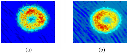
In our experiments we first set the SVR at orientation so as to obtain radial polarization, and then rotated the SVR by to obtain azimuthal polarization. In both cases the output power of the laser was about . The light emerging from the fiber laser was then imaged onto a CCD camera. The detected cross-section intensity distribution of the light for both cases are presented in Fig. 2. As evident, the expected doughnut shaped distributions were obtained, and the beam quality of the outgoing beam was measured to be . In order to determine the exact polarization distribution of the output light for both cases, we inserted a linear polarizer in front of the CCD camera, rotated it to several discrete orientations and detected the resulting intensity distributions.
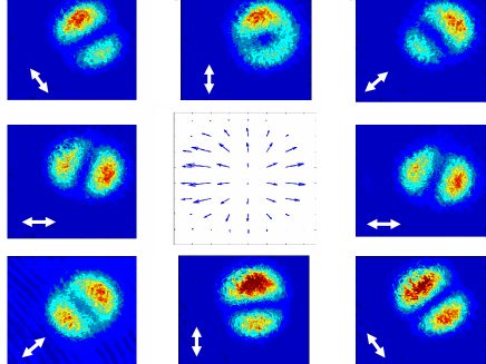
The results for eight representative orientations are presented in Figs. 3 and 4. Figure 3 shows the results when the SVR is oriented at . As evident from the detected distributions, the orientation of the common bisector of the two lobes is parallel to the direction of the external linear polarizer (denoted by the arrows), indicating radial polarization. Using these detected distributions, we calculated the local polarization at any point across the output beam Oron . The results are shown in the center of Fig. 3, where the arrows indicate the direction of the main axis of the local polarization ellipse. Using these results we determined that the radial polarization purity, defined as the amount of light that would pass through a radial polarizer, is 92%.
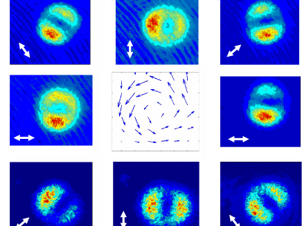
Figure 4 shows the results when the SVR is oriented at . As evident from the detected distributions, the orientation of the common bisector of the two lobes is normal to the direction of the linear polarizer (denoted by the arrows), indicating azimuthal polarization. Using these detected distributions, we calculate the local polarization at any point across the output beam. The results are shown in the center of Fig. 4, where the arrows indicate the direction of the main axis of the local polarization ellipse. We determined that the azimuthal polarization purity was 90%.
In order to compare our results of radially and azimuthally polarized output light with those of linearly polarized light, we removed the SVR shown in the configuration of Fig. 1 and inserted an aperture to suppress all modes higher than the mode. This resulted in our laser operating with a linearly polarized Gaussian mode, where the polarization purity of the output light was measured to be only 70%. On the other hand, when the laser operated with either radially or azimuthally polarized light, the polarization purity was 90% or better. These results indicate that redial and azimuthal polarizations are more suitable than linear polarization for multi-mode fiber lasers.
To conclude, we presented a simple and efficient method to produce radially and azimuthally polarized light with 90% or better purity directly from fiber lasers. Although our experiments were performed with relatively low output powers, we expect that our method could be extended to higher powers which are needed in many applications.
This research was supported in part by the Binational Science Foundation.
References
- (1) Q. Zhan and J. R. Leger. Opt. Exp., 10, 324, (2002).
- (2) K. S. Youngworth and T. G. Brown. Opt. Exp., 7, 77, (2000).
- (3) A. V. Nesterov and V. G. Niziev. J. Phys. D:Appl. Phys., 33, 1817, (2000).
- (4) K. Venkatakrishnan and B. Tan. J. of MicroMech. and MicroEng., 16, 2603, (2006).
- (5) M.O. Scully. Appl. Phys. B., 51, 238, (1990).
- (6) E. J. Bochove, G. T. Moore and M. O. Scully. Phys. Rev. A., 46, 6640, (1992).
- (7) I. Moshe, S. Jackel and A. Meir. Opt. Lett., 28, 807, (2003).
- (8) A. Witkowska, S. G. Leon-Saval, A. Pham and T. A. Birks. Opt. Lett., 33, 306, (2008).
- (9) T. Grosjean, A. Sabac and D. Courjon. Opt. Comm., 252, 12, (2005).
- (10) G. Volpe and D. Petrov. Opt. Comm., 237, 89, (2004).
- (11) T. Grosjean, D. Courjon and M. Spajer. Opt. Comm., 203, 1, (2002).
- (12) R. Oron, S. Blit, N. Davidson, A. A. Friesem, Z. Bomzon, and E. Hasman. Appl. Phys. Lett., 77, 3322, (2000).
- (13) N. Heckenberg, R. McDuff, C. Smith, and A. White. Opt. Lett., 17, 221, (1992).
- (14) H. Kawauchi, Y. Kozawa, S. Sato, T. Sato, and S. Kawakami, Opt. Lett. 33, 399-401 (2008).
- (15) J. -L. Li, K. -I. Ueda, M. Musha, A. Shirakawa, and Z. -X. Zhang. Opt. Lett., 32, 1360, (2007).
- (16) J. -L. Li, K. -I. Ueda, M. Musha, A. Shirakawa, and Z. -X. Zhang. Opt. Lett., 31, 2969, (2006).
- (17) G. Machavariani, Y. Lumer, I. Moshe, A. Meir, and S. Jackel Opt. Lett., 32, 1468, (2007).
- (18) G. Machavariani, S. Jackel, Y. Lumer, I. Moshe, and A. Meir Proc. SPIE, 6998, 69980L (2008).