Giant magnetoresistance in ultra-small Graphene based devices
Abstract
By computing spin-polarized electronic transport across a finite zigzag graphene ribbon bridging two metallic graphene electrodes, we demonstrate, as a proof of principle, that devices featuring 100% magnetoresistance can be built entirely out of carbon. In the ground state a short zig-zag ribbon is an antiferromagnetic insulator which, when connecting two metallic electrodes, acts as a tunnel barrier that suppresses the conductance. Application of a magnetic field turns the ribbon ferromagnetic and conducting, increasing dramatically the current between electrodes. We predict large magnetoresistance in this system at liquid nitrogen temperature and 10 Tesla or at liquid helium temperature and 300 Gauss.
The term spintronics has been coined to refer to the interplay between spin polarization and electrical conductance and is one of the major themes today in condensed matter and applied physics. A central concept in spintronics is that of giant magnetoresistance (GMR), discovered originally in layered structures alternating magnetic and non-magnetic transition metalsGMR . The resistance of the whole structure undergoes a large increase when the relative orientation of the magnetization in adjacent layers goes from parallel to antiparallel, provided that the non-magnetic layers are thinner than the spin relaxation length. This phenomenon represents the paradigm under which commercial devices such as magnetic reading heads operate nowadays.
Here we propose a new type of magnetoresistive device which makes use of the remarkable electronic properties of zig-zag graphene ribbonsNakada96 ; Fujita96 . Its operational principle is similar to that found in conventional GMR layers, with the difference that is entirely based on carbon. Our proposal is motivated by the spectacular progress in the fabrication of high mobility graphene based field effect transistorsGeim05 ; Kim05 ; Science06 and by the recent developments in the fabrication of graphene ribbonsNatmat ; Avouris ; kim07 ; Pablo07 with top-down techniques, as well as in the sinthesys of graphene ribbonsDai08 .
The electronic structure of infinite graphene ribbons has been studied thoroughly. Idealized graphene ribbons, with boundaries parallel to the crystallographic directions and boundary carbon atoms passivated with a single hydrogen atom, fall into two categories: armchair and zig-zag. Within the simplest one orbital tight-binding descriptionNakada96 , armchair ribbons can be either semiconducting or metallic, depending on their width, whereas in the case of zigzag ribbons two flat bands, associated with edge states, lie at the Fermi energy. These edge flat bands favor the appearance of magnetization on the edges when electron-electron repulsion is included in the calculation, either with a Hubbard modelFujita96 ; JFR08 ; Tomanek08 or with density functional theory (DFT)Son06 ; Cohen06 ; pisani . In the ground state the respective magnetization direction of the edges is antiparallel, and a gap opens in the band structureSon06 ; Cohen06 ; pisani ; JFR08 . This is the ground state. Slightly above in energy, the parallel magnetic configuration is conducting. Application of either a magnetic field or a transverse electric fieldCohen06 can make the ferromagnetic configuration more stable. Here we explore the former.
Both for conceptual and practical reasons our proposal is based on finite length graphene ribbons. For , the long range order predicted by mean field calculations is not robust, due to the proliferation of spin wave excitations of energy , with or for both antiferromagnetic and ferromagnetic alignments, respectivelyYazyev07 . In short ribbons, in contrast, there is a gap for spin waves. Quantum fluctuations between the manifold of equivalent mean field ground states would not alter the conducting properties of the system. Additionally, recent DFT calculationsMauri08 show that monohydrogenated zigzag ribbons are not the most stable edge configuration unless the hydrogen density is very small. Whereas this poses a severe problem for the chemical stability of infinite monohydrogenated zigzag ribbons, short magnetic ribbons, as well as other magnetic polycyclic aromatic hydrocarbonsWu07 , might be more stable.
Here we show that the spin driven metal insulator transition, predicted so far for infinite ribbons, is still present in short ribbons attached to conducting electrodes. Using a well-established methodologyMunoz06 extended to account for electron-electron interactions in a Hubbard model, we study both the magnetic and transport properties of a system in which two conducting graphene electrodes are coupled through a finite length graphene ribbon.
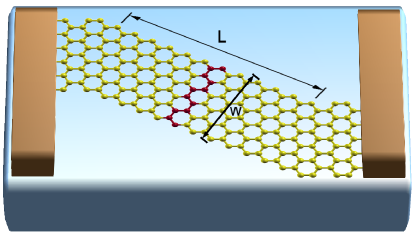
Statement of the problem and methodology.- We study the system depicted in Fig. 1: A short zig-zag graphene ribbon attached to two conducting graphene electrodes. In the case pictured in the figure we have chosen the electrodes to be semi-infinite metallic armchair graphene ribbons of width . Both the device and the electrodes are described with a Hubbard model for the orbitals with first-neighbor hopping and on-site repulsion , solved at a collinear mean field levelFujita96 ; JFR07 ; JFR08 ; JJP08 ; Tomanek08 ; Yazyev08 This approach is known to capture the main features of the ab-initio calculations, both for finiteJFR07 and infiniteJFR08 graphene systems. Thus, the mean-field Hamiltonian reads
| (1) |
where creates an electron at the orbital of atom with spin , is the occupation operator. Since the mean fields depend on the eigenstates of the mean field Hamiltonian, this defines a self-consistent problem which is solved by numerical interation. The converged solutions define a one body Hamiltonian for the electrons in the structure.
In this work we have to solve the self-consistent problem for an infinite system without translational invariance. This is done using the partition methodMunoz06 . We split the system in three sectors, the left and right electrodes and the central region. The Hamiltonian of Eq. (1) reads:
| (2) |
where are the mean field Hubbard Hamiltonians of the left and right electrodes and the central region and describes the hopping between the central region and the electrodes. Sufficiently away from the central region, the mean field Hamiltonian of the electrodes is identical to that of an infinite ribbon. In the case of the armchair electrodes, the effect of the Hubbard interactions in the charge neutrality point is a rigid shift of the bands without the appearance of magnetic moment and keeping their metallic character. The first step is the determination of the surface Green function of the semiinfinite electrodes, Munoz06 . This requires the solution of a self-consistent Dyson equation. Once this is done, the Green function of the central region reads:
| (3) |
with
This expression is a functional of the expectation values , through the central Hamiltonian . The Green function yields the density of states projected over the orbital with spin sitting in the atom in the device, is given by:
| (4) |
Here is a matrix of size , with being the number of atoms of the central region. In turn, the expectation values of the spin density are given by
| (5) |
The magnetic moment in a given atom I is defined as
Equations (3) and (5) define a self-consistent problem which is solved by numerical iteration. The solution provides a mean field description of the central region attached to the electrodes.
Within this formalism the Landauer conductance is given by with:
| (6) |
with
Results.- The size of the zig-zag ribbons is defined by two integer numbers, , the number of unit cells of the ribbon, and the number of zigzag rows in the unit cell. Thus, the length of the ribbon is , with Å and the width of the ribbon is given by .
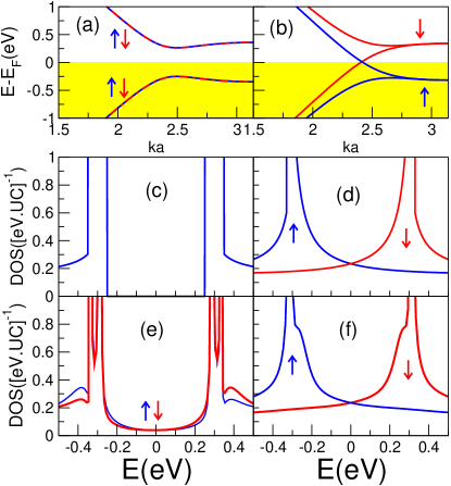
We verify first that magnetic solutions appear in short zigzag ribbons connected to conducting electrodes. As in the case of both isolated finite ribbonsScuseria and infinite ribbonsCohen06 , we obtain two kind of solutions, ferromagnetic and antiferromagnetic, depending on the initial guess in the iterative self-consistent procedure. We see how only the edge atoms of the zigzag ribbon are magnetic and how the size of the edge moments is larger away from the interface. In the case of the AF solution, the largest magnetic moment is for eV almost identical to the result of infinite ribbons. In Fig. 2 we compare the electronic structure of the finite size connected zigzag ribbons with the case of infinite ribbons, both for ferromagnetic (FM) and antiferromagnetic (AF) configurations. The electronic structure of the infinite ribbons is calculated taking advantage of crystal invariance and making use of the Bloch theoremJFR08 . Whereas AF infinite ribbons have a gap Son06 ; JFR08 and zero density of states (DOS) at (hereon set to zero), two bands cross for the FM ribbons, resulting in a finite density of states at . The same trend is observed in finite ribbons. The DOS of the AF configurations, summing over the atoms of a unit cell (see Fig. 2), presents a pseudogap. The DOS becomes more similar to the one of the infinite case both for longer ribbons and for unit cells in the middle of the ribbon. The small DOS inside the gap arises from the coupling to the electrodes. In contrast to the AF solution, the DOS of the FM solutions, again summing over the atoms of a unit cell (see Fig. 2), is that of a conducting system.
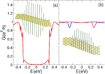
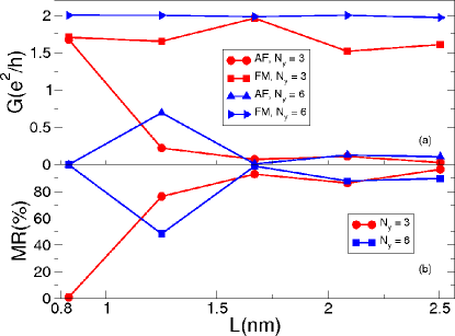
From the DOS we anticipate a strong dependence of the conductance on the magnetic configuration. Our calculations confirm this expectancy. In Fig. 3 we show the conductance curves for the ribbon. In the left panel we show how the transmission of the AF solution for is highly reduced, compared to the FM solution, shown in the right panel. This is the central result of our work: The conductance is strongly dependent on the relative orientation of the magnetization of the edges of the zigzag ribbon bridging the electrodes. In the ground state the ribbon is antiferromagnetic and the conductance is small or vanishes for sufficiently large . In Fig. 4 we plot the conductance at , both for AF and FM configurations, as a function of the ribbon length for two widths. Only for very short ribbons the conductance in the AF case is not vanishingly small, due to tunneling. The conductance of the FM state is always close to , value associated with the two bands, one per spin channel, that cross the Fermi energy. This conductance value is sensitive to the actual form of the graphene electrodes, but the vanishingly small values for the AF state are not.
As in standard GMR devices, the application of a magnetic field can force the ferromagnetic solution to be the ground state, resulting in a dramatic increase of the conductance. We define the magnetoresistance (MR) of each device as
| (7) |
where is the resistance and is the conductance calculated with the Landauer formula. In Fig. 4 we plot the MR as a function of the ribbon length for ribbons of width and . We see that, except for ribbons shorter than 1nm, the MR saturates to 100. The origin of the MR proposed here is different from that discussed by Brey and FertigBreyMR and that of Kim and Kimkim08 which require ferromagnetic electrodes. Our proposal is more similar to the original GMR experiments with current in plane in exchanged coupled multilayersGMR .
We now discuss the operational limits of our proposed device. There are three relevant magnitudes to be considered. First, the energy difference between the AF and the FM states, which depends both on the width of the ribbon and the length:
| (8) |
This expression has been obtained from the fitting to DFT calculations by Pisani et al.pisani Second, the temperature-dependent spin correlation length , over which magnetic order is lostYazyev07 . Finally, and neglecting the influence of the magnetic field on the orbital part of the wavefunctions, the critical switching magnetic field is defined through the equation
| (9) |
where is the total spin density of the FM configuration, for graphene and meV T-1.
The temperature determines the minimal value below which thermal fluctuations will make the AF unstable. It also determines the maximal value for the length of the ribbon above which magnetic order is lost. By choosing , we guarantee the maximum possible width for the ribbon through Eq. 8. This, in turn, provides the minimum critical switching field through Eq. 9. For instance, at room temperature, meV and nm. This yields nm and T. For liquid nitrogen temperatures (75 K) meV, nm, nm, and T. At He liquid temperatures (4 K) meV, nm, nm, and T. Using the extrapolation formula of Son et al.Son06 for the ribbon transport gaps a ribbon of nm has a gap of meV, which still larger than and standard bias voltages. In summary, there is a trade-off between the minimum temperature below which the AF ground state becomes unstable and the critical switching field. This trade-off is controlled by the spin correlation length. At high temperatures becomes prohibitively large. At liquid He temperatures, the critical field is bounded within reasonable ranges easily attainable in the lab.
Also the width of the electrodes does not need to be equal to the width of the zigzag channel. This would only introduce some additional scattering in the FM state, but never compromising the high conductance values.
In conclusion, we propose an ultra-small and chemically simple magnetoresistive device based on a zigzag ribbon joining metallic graphene electrodes. The conduction properties of this device change dramatically as the relative orientation of the magnetic edges of the ribbon go from parallel to antiparallel relative orientations upon application of a magnetic field. Even if from the operational point of view there are still challenges regarding room-temperature performance in small magnetic fields, a proof of principle has been demonstrated. From a more fundamental point of view, low-temperature experiments showing a drastic change in the resistance on applying strong magnetic fields would unambiguously signal the existence of magnetism in zig-zag graphene ribbons.
We acknowledge fruitful discussions with D. Soriano. This work has been financially supported by MEC-Spain (Grant Nos. MAT07-67845 and CONSOLIDER CSD2007-0010).
References
- (1) M. N. Baibich, J. M. Broto, A. Fert, F. Nguyen Van Dau, F. Petroff, P. Etienne, G. Creuzet, A. Friederich, and J. Chazelas, Phys. Rev. Lett. 61, 2472 (1988). G. Binasch, P. Grunberg, F. Saurenbach, and W. Zinn, Phys. Rev. B 39, 4828 (1989).
- (2) K. Nakada, M. Fujita, G. Dresselhaus, and M. S. Dresselhaus, Phys. Rev. B 54, 17954 (1996).
- (3) M. Fujita, K. Wakabayashi, K. Nakada, and K. Kusakabe, J. Phys. Soc. Jpn. 65, 1920 (1996).
- (4) K. S. Novoselov, A. K. Geim, S. V. Morozov, D. Jiang, M. I. Katsnelson, I. V. Grigorieva, S. V. Dubonos, and A. A. Firsov, Nature 438, 197 (2005).
- (5) Y. Zhang, Y. W. Tan, H. L. Stormer, and P. Kim, Nature 438, 201 (2005).
- (6) C. Berger, Z. Song, X. Li, X. Wu, N. Brown, C. Naud, D. Mayou, T. Li, J. Hass, A. N. Marchenkov, E. H. Conrad, P. N. First, and W. A. de Heer, Science 312, 1191 (2006).
- (7) A. Geim and K. Novoselov, Nature Materials 6, 183 (2007).
- (8) Z. Chen, Y. -M. Lin, M. J. Rooks, and P. Avouris, Physica E: Low-dimensional Systems and Nanostructures 40/2, 228 (2007).
- (9) M. Y. Han, B. Ozyilmaz, Y. Zhang, and P. Kim, Phys. Rev. Lett. 98, 206805 (2007).
- (10) B. Ozyilmaz, P. Jarillo-Herrero, D. Efetov, D. A. Abanin, L. S. Levitov, and P. Kim, Phys. Rev. Lett. 99, 166804 (2007).
- (11) X. Li, X. Wang, L. Zhang, S. Lee, and H. Dai, Science 319, 1229 (2008).
- (12) J. Fernández-Rossier, Phys. Rev. B. 77, 075430 (2008).
- (13) M. Wimmer, I. Adagideli, S. Berber, D. Tománek, and K. Richter, Phys. Rev. Lett. 100, 177207 (2008).
- (14) Y.-W. Son, M. L. Cohen, and S. G. Louie, Phys. Rev. Lett. 97, 216803 (2006).
- (15) Y.-W. Son, M. L. Cohen, and S. G. Louie, Nature 444, 347 (2006).
- (16) L. Pisani, J. A. Chan, B. Montanari, and N. M. Harrison, Phys. Rev. B 75, 064418 (2007).
- (17) O. V. Yazyev and M. I. Katsnelson, Phys. Rev. Lett. 100, 047209 (2008).
- (18) T. Wassmann, A. P. Seitsonen, A. M. Saitta, M. Lazzeri, and F. Mauri, Phys. Rev. Lett. 101, 096402 (2008).
- (19) J. Wu, W. Pisula, and K. Mullen, Chem. Rev. 107, 718 (2007).
- (20) F. Muñoz-Rojas, D. Jacob, J. Fernández-Rossier, and J.J. Palacios, Phys. Rev. B 74, 195417 (2006).
- (21) J. Fernández-Rossier and J. J. Palacios, Phys. Rev. Lett. 99, 177204 (2007).
- (22) J. J. Palacios, J. Fernández-Rossier, and L. Brey, Phys. Rev. B 77, 195428 (2008).
- (23) O. V. Yazyev, Phys. Rev. Lett 101, 037203 (2008).
- (24) O. Hod, V. Barone, and G. E. Scuseria, Phys. Rev. B 77, 035411 (2008).
- (25) L. Brey and H. A. Fertig, Phys. Rev. B 76, 205435 (2007).
- (26) W. Y. Kim and K. S. Kim, Nature Nanotechnology 3, 408 (2008).