On Electromagnetically Induced Transparency in the Degenerate -scheme
Abstract
Saint-Petersburg State University Physics Department,
Saint-Petersburg, 198504, Russia
Using an experimental work on “stopped light” as an example, we show how a classical phenomenon of linear optics – interference of polarized light – can imitate the effect of electromagnetically induced transparency
After the first impressive experiments on the so-called “slow light” kasapi ; hau , there have been reported observations, no less spectacular, made under much simpler experimental conditions. In one of the most popular publication of this sort lukin , the symptoms of retarded polarization-optical response of an atomic medium were regarded as manifestations of the effects of “slow” and “stopped” light (for more detail, see alex ). In this note, we attract attention to an instructive aspect of this misinterpretation, which, in fact, resulted from erroneous identification of the interference of polarized beams as the effect of electromagnetically induced transparency (EIT).
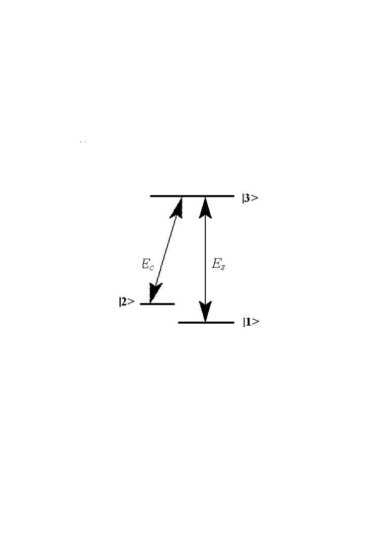
Recall that the EIT effect har is revealed, in its simplest form, under the action of a sufficiently strong resonant field onto a three-level quantum system with the -type energy diagram (Fig. 1). It appears that the action of the pump (control) field in one arm of the -scheme (with both the initial and final levels of the appropriate transition being empty) renders the system transparent for the weak probe (signal) field acting in the second arm provided that the frequency difference between the two fields coincides with the frequency of transition between the two lowest levels of the -scheme.
The narrow dip formed under these conditions in the absorption spectrum of the system (in the channel of the probe light - , Fig. 1) provides high steepness of the refractive index dispersion in the vicinity of the transparency point and can be revealed, in particular, in a giant reduction of the group velocity of light propagating in this medium. This is a gist of the slow light effect based on the phenomenon of electromagnetically induced transparency.
Turning to physical content of the EIT, we can recall that this effect is, in essence, a strongly asymmetric (with respect to intensities of the two fields) version of the effect of coherent population trapping agap usually detected as a dip in the luminescence excitation spectrum under comparable intensities of the fields. In its turn, the effect of coherent population trapping is a direct development of the effect of optically driven spin precession bell , with magnetic sublevels of the ground state serving as the lowest levels of the -scheme. And, eventually, the effect of optically driven spin precession is nothing else than the effect of optical orientation (or optical alignment) in the rotating coordinate frame happer . So, without restraining specificity of the EIT — the only inear (with respect to the probe light) effect among all the above resonant phenomena, we can say that EIT is just a modification of the effect of generalized optical alignment. In [3], the attempt was made to realize the EIT effect, so to say, on the lowest step of the above hierarchy, when the lowest levels of the -scheme are the degenerate magnetic sublevels of the ground state.
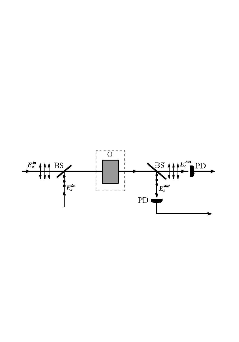
The experiments of [3] were performed on transition of 87Rb using a tunable diode laser as a light source and a Pockels cell for controlling the beam polarization. A specific feature of the experiment was that in the capacity of the control and signal (probe) beams were used orthogonal polarization components of the same laser beam. In other words, real variations of the light polarization were produced using the Pockels cell and were considered as a result of admixture of the orthogonally polarized probe beam to the control one. A simplified schematic of the experiment is shown in Fig. 2. The strong (control) and weak (signal) beams are combined on the input polarizing beamsplitter and then, after passing through the atomic system, are split again using the same polarization basis and are registered by photodetectors.
The basic experimental fact reported by the authors of [3], which, in authors’ opinion, should serve as the direct evidence for the EIT effect, is that the system under study is opaque for the probe light in the absence of the control beam and becomes virtually completely transparent in its presence. The authors consider this effect as that of nonlinear optics, the effect of optical controlling transmission of the medium. At first glance, it looks convincing. But is it really the case? Is it necessary that the optical element placed into the “black box” contoured in Fig. 2 by dashed line should be nonlinear to demonstrate the above effect of “controlling light by light”? Let us show that it is not.
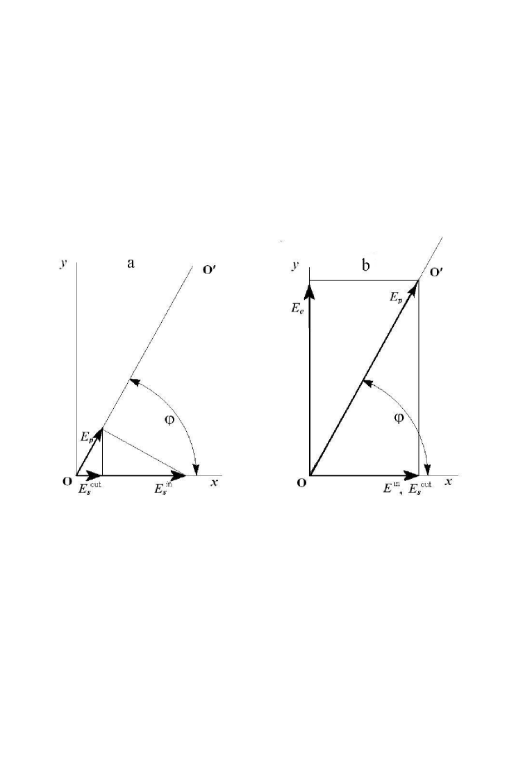
We will assume that the control and probe beams are polarized linearly rather than circularly (as in [3]). This changes absolutely nothing from the viewpoint of physics (because the system under study is amenable both to orientation and alignment), but makes the treatment more visual. We will also assume that the mutually coherent fields are in-phase, so that being summed at the input beamsplitter they form a linearly polarized light. The angle between the plane of polarization of this light and that of the probe beam will evidently be equal to arctan, where and are the amplitudes of the control and probe waves (Fig. 3).
Let us replace the cell with rubidium vapor in the “black box” by a linear polarizer with its polarizing direction making the same angle with the polarization plane of the probe. As a result, in the absence of the control field, the probe beam, on its way to the detector, will be first attenuated by this polarizer (according to the Malus law, the attenuation factor is ) and then, in the same degree, by the output beamsplitter (Fig. 3a). It is clear that total attenuation of the probe beam determined by the factor can be formally arbitrary large provided that the angle is close enough to 900.
So, transmission of the probe beam by the “black box” is rather low. Let us turn the control light on. Now the light outcoming from the input beamsplitter is again linearly polarized but its polarization plane exactly coincides with the polarizing direction of the polarizer in the “black box”, and the light passes through the polarizer without any attenuation and any change in its polarization state. In other words, with the control beam turned on, the “black box” becomes transparent for the whole incident light and, in particular, — what is important for us - for its horizontal polarization component, i.e., for the probe beam.
This is practically exact copy of the EIT effect described in lukin (neglecting dynamics of the process). In reality, the medium studied in [3] is nonlinear; the pump beam aligns it optically and thus controls its anisotropy. It means that the azimuth of the transmission axis of the “black box” is being set not manually, as in our hypothetical experiment, but rather by the light wave. For this reason, there arise some apparent discrepancies between the picture described above and observations of lukin . For instance, when, in our simplified arrangement, the control light is on, the probe light can be detected at the exit of the scheme even being absent at the entrance. However, as one can easily see, this is exactly what is observed in [3] in the demonstrations of “stopped light”, when, after preliminary manipulations with polarization of the light beam and subsequent dark pause, the signal in the channel of the probe light is observed with no probe light at the entrance. In the experiment, this signal cannot be observed for a long time because, after a certain time interval, the control beam aligns the atomic system along its polarization plane or, in other words, sets properly the polarizer of the “black box” ( = 90 o, Fig. 3), and the projection of the control beam onto the probe light channel vanishes. In our model, position of the “black box” polarizer is fixed, and, for this reason, the signal of the probe light does not disappear.
Thus, we see how easy the EIT effect can be simulated by interference of polarized light when the “control” and “probe” fields are just two orthogonal polarization components of the same beam.
There arises, however, a question: Perhaps this is not am imitation of the EIT effect but rather the EIT effect proper or, better to say, what it turns into in the degenerate -scheme? To a certain extent, this is true. But, first of all, there are no grounds to rename old, well known effects of classical optics unless we discovered anything new. Second, and most important, is that “freezing” phase difference between the probe and control waves in the degenerate -scheme changes symmetry of the problem. In the standard nondegenerate case of the EIT, anisotropy of the medium is provided exclusively by the control light, while the weak probe light monitors it in a nonperturbing way. In the case of the degenerate -scheme considered here, the probe light of arbitrarily low intensity affects anisotropy of the medium (in what way, depends on the value of the “frozen” phase) and, for this reason, is fundamentally unable to fulfill its function. In addition, optical medium with the anisotropy axis O - Oprime cannot be characterized by any optical constant with respect to probe light polarized along the -axis, and, correspondingly, one cannot ascribe any phase or group velocity to this light alex ; kozlov . In fact, the standard pattern of the EIT effect is destroyed when the inverse frequency spacing between the levels and becomes comparable with the time of measurement.
Note, in conclusion, that the apparent effect of controlling light by light in a single interference order is a trivial phenomenon. As applied to the polarization geometry under consideration, it can be described, in a comprehensive way, by the standard operation of multiplying Jones vector of the input light by the matrix of linear polarizer. Still, in some experimental situations, recognition of this phenomenon appears to be not so trivial. At least, paper [3], in which exactly this type of error was made, has gained unquestioning recognition of scientific community and remains so far widely cited in publications on “slow light”. This is why we considered this story to be instructive and deserving additional attention.
The author is grateful to E.B.Aleksandrov for useful discussions.
Fig. 1. Energy-level diagram (-scheme) illustrating common approach to observation of the coherence resonance of the states and . Specific feature of the EIT effect is that it is observed at and is linear with respect to probe field , while the effects of coherent population trapping and optically driven spin precession are observed in the fields of comparable amplitudes (more correctly, of comparable Rabi frequencies at the transitions - and - ).
Fig. 2. Simplified schematic of the experimental setup for observation of the EIT effect in the degenerate -scheme. and are the control and probe (signal) beams, BS – polarizing beamsplitters, PD – photodetectors, and O – object under study.
Fig. 3. Vector diagram describing transformation of the probe wave field in the arrangement of Fig. 2 with a polarizer in the “black box” in the absence (a) and in the presence (b) of the control field . The fields and are polarized along the - and -axes, respectively. The line O – O′ is directed along the polarizing direction of the polarizer. and are the probe field vectors at the entrance and at the exit of the optical system.
References
- (1) Kasapi A., Jain Maneesh, Yin G. Y., and Harris S. E., Phys. Rev. Lett., 74, 2447 (1995)
- (2) Hau L. V., Harris S. E., Dutton Z., and Behroozi C. H., Nature, 397, 594 (1999)
- (3) Phillips D. F., Fleischhauer A., Mair A., Walsworth R. L., and Lukin M.D., Phys. Rev. Lett., 86, 783 (2001)
- (4) Aleksandrov E.B. and Zapasskii V.S., Physics: Uspekhi, 47, 133 (2004)
- (5) Harris S.E., Physics Today, 50(7), 36 (1997)
- (6) Agap’ev B.D. et al., Usp. Fiz. Nauk, , 193, 1 (1993)
- (7) Bell W.E.and Bloom A.L., Phys. Rev. Lett., 6 (6), 280 (1961)
- (8) Happer W., Rev. Mod. Phys., 44, 169 (1972)
- (9) Kozlov G.G., Aleksandrov E.B., and Zapasskii V.S., Opt. Spectr., 97, 909 (2004)