e-mail
lfzhu@aphy.iphy.ac.cn, Phone
+86-10-82649438, Fax +86-10-62553698
e-mail
bgliu@aphy.iphy.ac.cn, Phone
+86-10-82649437, Fax +86-10-62553698
2 Beijing National Laboratory for Condensed Matter Physics, Beijing 100190, China
XXXX
Half-metallic ferrimagnet formed by substituting Fe for Mn in semiconductor MnTe
Abstract
A ternary ferrimagnetic half-metal, constructed through substituting 25% Fe for Mn in zincblende semiconductor MnTe, is predicted in terms of accurate first-principles calculations. It has a large half-metallic (HM) gap of 0.54eV and its ferrimagnetic order is very stable against other magnetic fluctuations. The HM ferrimagnetism is formed because the complete moment compensation in the antiferromagnetic MnTe is replaced by an uncomplete one in the Fe-substituted MnTe. This should make a novel approach to new HM materials. The half-metal could be fabricated because Fe has good affinity with Mn, and useful for spintronics.
pacs:
75.90.+w, 75.50.Pp, 75.47.-m, 75.30.-m1 Introduction
Half-metallic (HM) ferromagnets have attracted much attention because they have band gaps at the Fermi energy for one electronic spin channel and are metallic for the other channel[1, 2]. A lot of HM ferromagnetic (FM) materials have been found [3, 4, 5, 6, 7, 8, 9]. Accurate first-principles calculations have revealed HM ferromagnetism in binary transition metal chalcogenides and pnictides in the zincblende and wurtzite structures[10, 11, 12, 13, 14, 15]. It is exciting that a Singapore group, stimulated by the theoretical prediction of zincblende CrTe (z-CrTe)[14, 15], has fabricated z-CrTe samples of 100 nm thickness[16]. It has also been reported that half-metallic ferrimagnets can be formed by introducing Cr antisites in CrAs or CrSb[17]. It is still highly desirable to search for novel semiconductor-compatible half-metals with high Curie temperature for potential spintronic applications [18].
Magnetic materials with and based on zincblende structure are very interesting to spintronic applications. Zincble-nde MnTe (z-MnTe) is one of a few antiferromagnetic (AF-M) semiconductors. Although MnTe crystallizes into a NiAs phase, the metastable z-MnTe has been grown by molecular beam epitaxy (MBE) growth technique[19] and semibulk (about 1 micrometer thick) film samples of z-MnTe have been fabricated[20] because z-MnTe is only 0.02eV per formula unit higher in total energy than the NiAs-type MnTe. Ternary Cr-doped NiAs-type manganese tellurides, Mn1-x-CrxTe, with being up to 14%, have been fabricated, in which the substitution of Cr for Mn leads to a change from an AFM semiconductor of MnTe to a FM (or ferrimagnetic) semiconductor of Mn1-xCrxTe[21]. Therefore, z-MnTe should be an interesting novel approach to explore promising magnetic semiconductors and HM compounds.
In this paper, we perform first-principles study on structural, electronic, and magnetic properties of the 25%-Fe-doped z-MnTe. The substitution of Fe for Mn results in a transition from the AFM semiconductor of z-MnTe to the ferrimagnetic half-metal of Mn3FeTe4. We understand the mechanism of the magnetism and the magnetic transition through investigating the atomic and electronic structures of Mn3FeTe4 in comparison with those of z-MnTe.
The remaining part of this paper is organized as follows. In next section we present our computational detail. In the third section we shall present our optimized results of crystal structures and investigate the stability of the ferrimagnetism against magnetic fluctuations. In the fourth section we shall present the electronic structures and discuss the mechanism for the half-metallic ferrimagnetism. Finally we shall make some discussions and give our conclusion.
2 Computational detail
To perform the calculations, we use the package WIEN2K[22], which is based on full-potential linearized augmented plane wave method within the density-functional theory (DFT)[23]. The Perdew-Bur-ke-Ernzerhof 1996 version[24] of the generalized gradient approximation (GGA) is used for the exchange-correlation potential. Full relativistic effects are calculated for core states, and the scalar relativistic approximation is used for valence states. We investigate the effect of the spin-orbit coupling, but still present the results without spin-orbit coupling in the following because it does not affect our main conclusions. For different magnetic structures we use different but appropriate k points in the first Brillouin zones and make the expansion up to l=10 in muffin tins. is set to 8.5 for z-MnTe and to 7.0 for Mn3FeTe4 without affecting our conclusions. The self-consistent calculations are considered to be converged when the integrated charge difference per formula unit between input and output charge density is less than 0.0001.
3 Optimized crystal structures
Recent inelastic ne-utron-scattering experiment has revealed that the stable ma-gnetic structure of z-MnTe is collinear type-III AFM order of Mn spins in a double conventional unit cell[25, 26], rather than early type-I AFM order in single conventional unit cell[27] or noncollinear type-III AFM order suggested in terms of previous neutron-diffraction result[20]. Therefore, we consider only collinear spin configurations in the following.
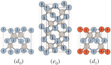
Five spin configurations , , , and can be constructed for z-MnTe. is a FM structure with four Mn moments being in parallel. and , obtained by reversing one Mn moment respectively at the face-center and on the vertex of , are ferrimagnetic structures and equivalent with each other. and are the type-I AFM (AFM-I) structure with single conventional cell[27] and the type-III AFM (AFM-III) structure with double unit cells[25], respectively, as shown in Fig. 1. By substituting Fe for Mn on the vertex in the single MnTe cell of , we get correspondingly four FM (or ferrimagnetic) structures , , , and of Mn3FeTe4. is the most stable among them and is shown in Fig. 1. Generally speaking, to get an AFM structure we construct a supercell of two unit cells and make the moments in one unit cell opposite to those in the other. are all possible FM (or ferrimagnetic) structures one can construct without enlarging the magnetic unit cell. We construct all possible AFM structures based on them, and the results for the most stable AFM structure (as the representative) are shown in Table 1.
| z-MnTe | |||||
| SG | 216 | 215 | 215 | 111 | 122 |
| MO | FM | FM | FM | AFM | AFM |
| (/ Å) | 6.393 | 6.314 | 6.314 | 6.290 | 6.290/12.580 |
| (eV) | 0.712 | 0.196 | 0.196 | 0.020 | 0 |
| M(B) | 20.000 | 10.00 | 10.00 | 0.000 | 0.000 |
| (eV) | 0.90 | 0.90 | 1.30 | 1.35 | |
| Mn3FeTe4 | |||||
| SG | 215 | 215 | 111 | 111 | 35 |
| MO | FM | FM | FM | FM | AFM |
| (/ Å) | 6.305 | 6.244 | 6.251 | 6.223 | 8.822/12.476 |
| (eV) | 0.764 | 0.114 | 0.222 | 0 | 0.125 |
| M() | 18.226 | 11.000 | 9.000 | 1.000 | 0.000 |
| (eV) | 0.21 | 0.16 | 0.54 | ||
All the above structures, both FM and AFM, are optimized fully. The moment and electronic structures are calculated with the lattice constants of the optimized structures. Our calculated results are summarized in Table 1. It is clear that the most stable structure tends to have a small equilibrium lattice constant. As is shown in Table 1, the two FM structures ( and ) and the four ferrimagnetic structures (, , and ), having large magnetic moments, are unfavorable in total energy. For z-MnTe, AFM-III and AFM-I , with the total moments being 0, are favorable in total energy, and is 5meV per formula unit lower than , being in agreement with experimental fact that is the ground-state phase of z-MnTe with a semiconducting gap of about 3.2eV[19]. The most stable structure for Mn3FeTe4, however, is not any AFM structure, but the ferrimagnetic structure with an absolute total moment of 1.000. It is lower by 0.125eV per formula unit in total energy than the lowest AFM structure .
| z-MnTe | Mn3FeTe4 | ||
|---|---|---|---|
| Mn1 | 4.180 | 4.130 | |
| Mn2 | -4.180 | -4.114 | |
| Fe | 3.157 | ||
| Te | 0.000 | 0.036 | |
| Inter | 0.000 | -0.095 | |
| Total | 0.000 | -1.000 |
We summarize the partial magnetic moments (B) projected in the muffin-tin spheres of Mn1, Mn2, Fe, and Te atoms and in the interstitial region in the most stable structures z-MnTe and Mn3FeTe4 in Table 2. The corresponding total magnetic moments also are presented for comparison. It is worth noting that there are two Mn1 atoms and two Mn2 ones in z-MnTe , but we have one Mn1 atom, one Fe atom, and two Mn2 atoms in Mn3FeTe4 , as shown in Fig. 1. It is obvious that the partial substitution of Fe for Mn leads to the transferring of a little magnetic moments from the Mn atoms to the Te atoms and the interstitial region. Mn3FeTe4 has a total moment of -1.000 B because Fe has one more electron, or one less magnetic moment, than Mn.
4 Electronic structures and magnetic mechanism
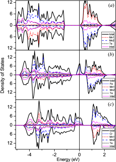
The spin-dependent density of states (DOS) of the AFM-III MnTe are presented in Fig. 2(). The primitive cell of AFM-III MnTe consists of 2 Mn1 (with spin up), 2 Mn2 (with spin down), and 4 Te atoms. The valence bands are formed by 10 and 12 states. The 10 lowest conduction bands originate from Mn states. The Mn moments are coupled with a superexchange interaction through the nearest Te atoms, which yields the antiferromagnetism. The spin exchange splitting is about 4.7eV, as shown in Fig. 2().

The spin-dependent density of states (DOS) and energy bands of the Mn3FeTe4 are presented in Fig. 2() and Fig. 3, respectively. The Fermi level is set to zero. The filled bands between -5eV and -0.6eV, consisting of 10 states and 12 states for each spin channel, are similar to those of the MnTe. The main difference is that there are partly-filled majority-spin bands across the Fermi level in the case of the Mn3FeTe4. The minority-spin bands still have a gap of 1.12eV, a little smaller than the Kohn-Sham gap, 1.35eV, of the MnTe. The Mn3FeTe4 has 0.54eV as its HM gap which is defined as the smaller of - and -, where is the bottom of the minority-spin conduction bands and the top of the minority-spin valence ones[14, 15].
The 25% Fe substitution for Mn results in a cell consisting of 2 Fe, 6 Mn, and 8 Te atoms. The spin orientations cannot remain the same as those of AFM-III MnTe because Fe has one more electron than Mn. Instead, the magnetic order is reorganized so that the 16-atom cell is divided into two equivalent smaller 8-atom ones which would have AFM-I structure if we neglect the difference between Fe and Mn. As a result, we obtain a ferrimagnetic order because the Fe moment cannot completely compensate the opposite Mn moment. The substitution does not substantially change the valence bands, but moves some majority-spin states downwards with respect to those of the z-MnTe because the Fe states are a little lower than those of Mn ones in energy. The majority-spin bands at the Fermi level, belonging to a doublet, are half-filled because there is only one electron for them. The HM ferrimagnetism is achieved because we still have a gap across the Fermi level for minority-spin channel.
We have studied similar 25%-Cr-doped MnTe, Mn3Cr-Te4. Its stable structure also exhibits HM ferrimagnetism. The results for Mn3CrTe4 are consistent with Nakamura et al’s through doping 75% Mn into z-CrTe [28]. The spin-dependent density of states for the most stable structure of Mn3CrTe4 are also given in Fig. 2(). Cr has four electrons, one less than Mn. The Cr states are a little higher than those of Mn in energy, which results in the partially occupied Cr impurity bands in the majority-spin bands and the open gap in the minority-spin bands.
By comparing the DOSs of the Mn3FeTe4 and Mn3Cr-Te4 in Fig. 2, we can explain the origin of their ferrimagnetism uniformly according to the number of electrons in the transition metal atoms and the energy levels of states. The substitution of Fe for Mn or Cr for Mn changes the distribution of states at the fermi level and results in the ferrimagnetism.
5 Discussion and conclusion
All of our presented results are calculated with GGA, although local density approximation (LDA) yields almost the same results. It is worth noting that a developed single-ion implantation technique recently was used to implant dopant ions one-by-one into a semiconductor[29]. That is, both the number and the position of the dopant atoms in the semiconductor are precisely controlled. As a result, the promising half-metals predicted in this paper could be realized by using such techniques.
In summary, we have predicted a ternary half-metal Mn3FeTe4, constructed by substituting Fe for Mn in semiconductor z-MnTe, in terms of our accurate first-principles calculations. The substitution results in a transition from the AFM semiconductor MnTe to the HM ferrimagnet of the Mn3FeTe4. The HM ferrimagnetism is stable against antiferromagnetic fluctuations. The large HM gap implies a possible high Curie temperature[30]. The Mn3FeTe4 could be fabricated experimentally soon because of the good affinity of Fe to Mn, and it could be used in spintronics.
This work is supported by Nature Science Foundation of China (Grant Nos. 10874232, 10774180, 90406010, and 60621091), by the Chinese Academy of Sciences (Grant No.KJC-X2.YW.W09-5), and by Chinese Department of Science and Technology (Grant No. 2005CB623602).
References
- [1] S. A. Wolf, D. D. Awschalom, R. A. Buhrman, J. M. Daughton, S. von Molnar, M. L. Roukes, A. Y. Chtchelkanova, and D. M. Treger, Science 294, 1488 (2001).
- [2] W. E. Pickett and J. S. Moodera, Phys. Today 54, 39 (2001).
- [3] R. A. de Groot, F. M. Mueller, P. G. van Engen, and K. H. J. Buschow, Phys. Rev. Lett. 50, 2024 (1983).
- [4] R. A. de Groot, Physica B 172, 45 (1991).
- [5] J. W. Dong, L. C. Chen, C. J. Palmstrom, R. D. James, and S. McKernan, Appl. Phys. Lett. 75, 1443 (1999).
- [6] S. M. Watts, S. Wirth, S. von Molnar, A. Barry, and J. M. D. Coey, Phys. Rev. B 61, 9621 (2000).
- [7] F. J. Jedema, A. T. Filip, B. van Wees, Nature 410, 345 (2001).
- [8] S. Soeya, J. Hayakawa, H. Takahashi, K. Ito, C. Yamamoto, A. Kida, H. Asano, and M. Matsui, Appl. Phys. Lett. 80, 823 (2002).
- [9] J. M. D. Coey, M. Viret, and S. von Molnar, Adv. Phys. 48, 167 (1999).
- [10] S. Sanvito and N. A. Hill, Phys. Rev. B 62, 15553 (2000).
- [11] Y. -Q. Xu, B. -G. Liu, and D. G. Pettifor, Phys. Rev. B 66, 184435 (2002).
- [12] B. -G. Liu, Phys. Rev. B 67, 172411 (2003).
- [13] W. -H. Xie, B. -G. Liu, and D. G. Pettifor, Phys. Rev. B 68, 134407 (2003).
- [14] W. -H. Xie, Y. -Q. Xu, B. -G. Liu, and D. G. Pettifor, Phys. Rev. Lett. 91, 037204 (2003).
- [15] B. -G. Liu, in: Half-metallic Alloys-Fundamentals and Applications, edited by I Galanakis and P. H. Dederichs, Lecture Notes in Physics Vol. 676, (Springer, Berlin, 2005), pp.267-291.
- [16] M. G. Sreenivasan, K. L. Teo, M. B. A. Jalil, T. Liew, T. C. Chong, and A. Y. Du, IEEE Transactions on Magnetics 42, 2691 (2006).
- [17] I. Galanakis, K. Ozdogan, E. Sasloglu, and B. Aktas, Phys. Rev. B 74, 140408(R) (2006).
- [18] C. M. Fang, G. A. de Wijs, and R. A. de Groot, J. Appl. Phys. 91, 8340 (2002).
- [19] S. M. Durbin, J. Han, O. Sungki, M. Kobayashi, D. R. Menke, and R. L. Gunshor, Appl. Phys. Lett. 55, 2087 (1989).
- [20] T. M. Giebultowicz, P. Klosowski, N. Samarth, H. Luo, J. K. Furdyna, and J. J. Rhyne, Phys. Rev. B 48, 12817 (1993).
- [21] Y. B. Li, Y. Q. Zhang, N. K. Sun, Q. Zhang, D. Li, J. Li, and Z. D. Zhang, Phys. Rev. B 72, 193308 (2005).
- [22] P. Blaha, K. Schwarz, P. Sorantin, and S. B. Trickey, Comp. Phys. Comm. 59, 399 (1990).
- [23] P. Hohenberg and W. Kohn, Phys. Rev. 136, B864 (1964); W. Kohn and L. J. Sham, Phys. Rev. 140, A1133 (1965).
- [24] J. P. Perdew, K. Burke, and M. Ernzerhof, Phys. Rev. Lett. 77, 3865 (1996).
- [25] B. Hennion, W. Szuszkiewicz, E. Dynowska, E. Janik, and T. Wojtowicz, Phys. Rev. B 66, 224426 (2002).
- [26] S. -H. Wei and A. Zunger, Phys. Rev. B 48, 6111 (1993).
- [27] S. -H. Wei and A. Zunger, Phys. Rev. Lett. 56, 2391 (1986).
- [28] K. Nakamura, T. Ito, and A. J. Freeman, Phys. Rev. B 72, 064449 (2005).
- [29] S. Takahiro, O. Shintaro, K. Takahiro, O. Iwao, Nature 437, 1128 (2005).
- [30] J. Kubler, Phys. Rev. B 67, 220403 (2003).