Features of spin-charge separation in the equilibrium conductance through finite rings
Abstract
We calculate the conductance through rings with few sites described by the model, threaded by a magnetic flux and weakly coupled to conducting leads at two arbitrary sites. The model can describe a circular array of quantum dots with large charging energy in comparison with the nearest-neighbor hopping . We determine analytically the particular values of for which a depression of the transmittance is expected as a consequence of spin-charge separation. We show numerically that the equilibrium conductance at zero temperature is depressed at those particular values of for most systems, in particular at half filling, which might be easier to realize experimentally.
pacs:
75.40.Gb, 75.10.Jm, 76.60.EsI Introduction
Recent advances in nanotechnology allow the fabrication of different nanostructures, motivated either by technological interest or the possibility of testing theories for strongly correlated electrons. One example is the realization of the Kondo effect in systems with one quantum dot (QD). gold1 ; cro ; gold2 ; wiel Another one is a study of the metal-insulator transition in a chain of 15 QD’s. kou Systems of a few QD’s have been proposed theoretically as realizations of the two-channel Kondo model, oreg ; zit the so called ionic Hubbard model, ihm and the double exchange mechanism. mart Recently it has been studied how the Kondo resonance splits in two in a system of two QD’s, one of them non-interacting. dias ; vau
It is known that strong correlation effects invalidate the conventional quasiparticle description of Fermi liquids and in one dimension lead to a fractionalization of the electronic excitations into pure charge and spin modes, as it has been shown using bosonization. Haldane ; Schulz ; kv ; gia ; kurt In this field theory, it becomes clear that in general (except in some particular models rc ) the Hamiltonian at low energies can be separated into independent charge and spin parts. While this separation is an asymptotic low-energy property in an infinite chain, exact Bethe ansatz results for the Hubbard model in the limit of infinite Coulomb repulsion have shown that the wave function factorizes into a charge part and a spin part for any size of the system. ogata
Several experiments were reported that find indirect evidences of spin-charge separation Voit1 ; Voit2 ; Kim ; Taillefer ; Qimiao , and it could also be potentially observed kurt in systems such as cuprate chains and ladder compounds, DagottoRice and carbon nanotubes. egger
From the theoretical point of view, several calculations involving rings have been made. The real-time evolution of electronic wave packets in Hubbard rings has shown a splitting in the dispersion of the spin and charge densities as a consequence of the different charge and spin velocities. Jagla1 ; uli Pseudospin-charge separation has also been studied theoretically in quasi-one-dimensional quantum gases of fermionic atoms. recati ; ke
The transmittance through Aharonov-Bohm rings of length modeled by a Tomonaga-Luttinger liquid and connected to conducting leads at and has been studied by analytical methods.Jagla ; meden It is found that the transmittance integrated over an energy window shows dips when the threaded magnetic flux corresponds to particular fractional values of the flux quantum . This is rather striking because in the non-interacting case, one has a dip in the transmittance only when the applied flux , for which the conductance vanishes due to a negative interference of the waves traveling through both arms of the interferometer. Jagla and Balseiro obtained that the values of the flux at the dips are multiples of , where () is the charge (spin) velocity, when is a simple fraction. This allows an appealing simple “classical” interpretation of the phenomenon: the electrons enter the ring at position , splitting into charge and spin components, which travel independently inside the ring, until they recombine at before leaving the ring. When the difference between the Aharonov-Bohm phases captured by the charges traveling in both possible senses of rotation is an odd multiple of , the transmittance is depressed. More recent work, however, indicates that the relevant ratio for the dips is in general , where is the current velocity. meden
Numerical calculations of the transmittance through finite rings described by the model, integrated over an energy window also show clear dips for fractional applied fluxes. nos1 This model is expected to be a realistic description for a ring of quantum dots if the charging energy is large in comparison with the nearest-neighbor hopping . Recently we have discussed the extension of these results to ladders of two legs as a first step to higher dimensions. julian
All the above calculations used a formalism valid at equilibrium and zero temperature, and an integration over a finite energy window to obtain the dips. In particular in Ref. nos1, this window contained all low-energy spin excitations with the same charge quantum numbers (see Section III)). In principle, this integration can be justified invoking a finite voltage bias or temperature. However, in the interacting case, under an applied bias, it is not clear that the total current through the device can be obtained integrating the equilibrium transmittance. In particular, it might happen that a particle injected to the ring leaves it in an excited spin state after leaving it. This process is not taken into account in the calculations. The effect of temperatures of the order of the spin excitation energy is also difficult to predict. These shortcomings raise the question of whether the dips can be really observed in an experimental setup.
In this work, we analyze the origin of the dips in the transmittance as a function of applied flux in finite rings described by a strongly correlated model and in particular, the model. We discuss the conditions for which the intensity of the first peak in the equilibrium conductance at zero temperature as a function of the gate voltage has a flux dependence with characteristic dips as a consequence of spin-charge separation.
In Section II we present the model, the formalism used to calculate the conductance, and some general statements on the conditions for which dips or reduced conductances are expected. In Section III we discuss the model with (equivalent to the Hubbard model with infinite ), for which definite conclusions can be drawn on the basis of its exactly known energy spectrum. Section IV contains numerical results for some particular systems at which dips in the conductance at certain fluxes are expected at equilibrium and small temperatures. Section V is a summary and discussion.
II Model and relevant equations
II.1 Hamiltonian
We consider a ring of sites, weakly connected to non-interacting leads at sites and (Fig. 1). Usually was taken, Jagla ; meden ; nos1 but we will see that odd and/or lead to interesting new results.

The Hamiltonian can be written as
| (1) |
The first term describes the isolated ring, with on-site energy modified by a gate voltage , and hoppings modified by the phase due to the circulation of the vector potential. For most of the results of this paper we use the model to describe the ring,
| (2) | |||||
where , is the spin operator at site and double occupancy is not allowed at any site of the ring. The second term corresponds to two tight-binding semi-infinite chains for the left and right leads
| (3) |
The third term in Eq. (1) describes the coupling of the left (right) lead with site 0 () of the ring
| (4) |
II.2 Conductance
To calculate the conductance through the ring, one needs, in principle, to know some Green’s functions of the complete system. meir However, when the ground state of the isolated ring is non-degenerate, and the coupling between the leads and ring is weak, the equilibrium conductance at zero temperature can be expressed to second order in in terms of the retarded Green’s function for the isolated ring between sites and : . Jagla ; ihm For an incident particle with energy and momentum , the transmittance reads
| (5) |
where
| (6) |
play the role of a correction to the on-site energy at the extremes of the leads and an effective hopping between them respectively.
Although derived from perturbation theory, this equation is in fact exact for a non-interacting system. However, in general, for an odd number of electrons, the ground state of the isolated ring is Kramers degenerate for a system with time reversal symmetry and the equation ceases to be valid, missing the physics of the ensuing (non-perturbative) Kondo effect in which the electrons of the leads screen the spin of the ring. ihm ; lobos Nevertheless, the characteristic energy of this Kondo effect decreases exponentially with decreasing and therefore for small enough the Kondo effect is destroyed by a Zeeman term or temperature small in comparison with the other energy scales in the problem. Here, we assume this situation. The effect of a Zeeman term on the conductance in the Kondo regime, has been explicitly shown mapping the problem to an effective Anderson model and solving it by non-perturbative methods. ihm In addition, the main conclusions of this work are of qualitative nature and are not affected by the accuracy of Eq. (5).
The conductance is , where or 2 depending if the spin degeneracy is broken or not, ihm and is the Fermi level, which we set as zero (half-filled leads). As the gate voltage is varied a peak in the conductance is obtained when there is a degeneracy in the ground state of the ring for two consecutive number of particles: , where is the ground state energy of with electrons. To simplify the discussion, and without loss of generality, we assume that we start with electrons in the ring and apply a negative gate voltage in such a way that a peak in the conductance is obtained at a critical value when the number of electrons in the ring changes from to electrons. Note that Eq. (5) formally gives more peaks in the transmittance when at several values of excited states of electrons are reached (). However these peaks are in principle not experimentally accessible since the ground state has less than particles for . In any case, the information on the excited states of electrons is relevant to explain not only the position of the dips as a function of flux in the integrated transmittance, Jagla ; meden ; nos1 but also the values of the flux at which particular reductions of the intensity of the observable first peak in the conductance are obtained.
II.3 Dips in the conductance
The values of the flux for which dips or reduced conductances are expected, correspond to some particular crossings of the energy levels of electrons. Far from these crossings, and to leading order in , the transmittance as a function of gate voltage has a Lorentzian shape reaching the maximum value () for such that (where the subscript refers to any state in the subspace of electrons) and half-width at half maximum
| (7) |
where is the ground state in the subspace of electrons assumed non-degenerate. ihm This assumption is always true in the presence of a small Zeeman magnetic field except at particular values of the flux that do not correspond to , which are not relevant for the present analysis.
Keeping this assumption, some conclusions can be drawn for the general case using symmetry arguments. Using the Lehman’s representation, the part of the Green’s function that enters the transmittance [Eq. (6)] when a particle is destroyed is:
| (8) |
Since the ring is invariant under rotations that map each site to its consecutive one , the eigenstates of are also eigenstates of . Denoting as the wave vector of the state , one has , and therefore . Replacing above one obtains
| (9) |
At the values of the flux for which two states of electrons and are degenerate, assuming that the corresponding matrix elements entering Eq. (9) are nonzero, clearly only these two states (which correspond to the dominant poles of ) contribute significantly to the Green’s function at the Fermi energy () when (which displaces all rigidly with respect to ) is tuned in such a way that . Replacing Eq. (9) with only these two leading terms in Eqs. (5) and (6) one has an analytical expression for in terms of two matrix elements, proportional to and (Eq. (7)) and a relative phase between them in (Eq. (9)). It is easy to see that if , the transmittance for has the same form for a non-degenerate state, but with a width equal to the sum of the individual ones. In this case, nothing dramatic happens. In particular the integrated transmittance in a window which includes those levels as a function of flux does not change at the crossing between and .
If, however, , and thus the transmittance, which is proportional to , (Eqs. (5) and (6)), are reduced near the crossing. This effect is more noticeable if and . In any case, if , the above mentioned analytical expression vanishes at the crossing point and the transmittance as a function of gate voltage shows a peak with a dip inside (Fig. 4).
Note that these results are independent of the particular model used. In particular if the conductance through a ring with electrons is measured, with leads connected near 180 degrees () and the ground state for electrons has a level crossing involving two wave vectors differing in with odd for a given flux, then the conductance shows a dip at that flux.
III Analytical results for
The general results described above can be made more explicit for . In this case, the model is equivalent to the Hubbard model with infinite on-site repulsion , for which the wave function can be factorized into a spin and a charge part. ogata ; caspers ; nos1 Therefore, spin-charge separation becomes apparent. For each spin state, the system can be mapped into a spinless model with an effective flux which depends on the total spin. While the analysis given below can be made using the Bethe ansatz formalism, ogata here we follow the elegant method of Caspers and Ilske. caspers For a system of particles one can construct spin-wave functions which transform under the irreducible representations of the group of cyclic permutations of the spins of the -site system. Each of these representations is labeled by a “spin” wave vector , where the integer characterizes the spin wave function. The total energy and momentum (in an appropriate gauge) of any state of the ring have simple expressions:
| (10) | |||||
| (11) | |||||
| (12) |
where the integers characterize the charge part of the wave function and .
The calculation of the Green’s functions becomes very involved due to difficulties in handling the wave functions. However, even without calculating the matrix elements entering Eq. (9), we can predict the positions of dips in the transmittance from a knowledge of the energies and momenta of the eigenstates.
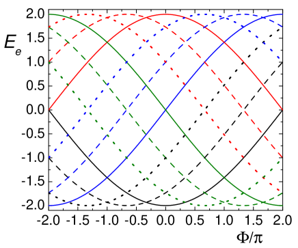
Let us analyze first the level crossings for even and (the most studied case Jagla ; meden ; nos1 ) with odd. We recall the reader that we start with a system with electrons and create a hole, leading to an intermediate state with electrons. The energy levels for the case with , are shown in Fig. 2. In the subspace with electrons, the ground state (with energy ) for has occupied momenta , with consecutive , , …, , and therefore . As the flux increases to , this state evolves to the state , in which is replaced by with . Therefore we can write . The lower “charge band” (used usually to integrate the transmittance nos1 ) extends between and . Clearly from Eq. (10) and a state exists with all opposite to those of . In the enlarged interval , the ground state energy is reached for when (full lines in Fig. 2). Now keeping the same charge quantum numbers as , but allowing spin states with , new eigenfunctions appear, whose energies and momenta are given by , . These states reach the ground state energy at (dashed and dotted lines in Fig. 2). note The crossings of energy levels at low energies take place at intermediate points between any two of these minima . When is odd (even) the relative phase (1) and there is (there is not) a dip in the integrated transmittance. Therefore, the positions of the dips are located at
| (13) |
with integer. These are also the positions where crossings in the (experimentally accessible) ground state for particles take place (, see Fig. 2). note
The same expression is valid for even but in this case for , the minimum energy lies at , and the crossings occur when .
Performing the sums in Eqs. (10) and (11) using the quantum numbers that lead to the minimum energy, as explained above, analytical expressions are obtained for the ground state energy and momentum as a function of flux for sites and particles, and . Defining
| (14) |
and writing in the form
| (15) |
where nint denotes the nearest integer to , one obtains
| (16) | |||||
| (17) |
For odd , the transmittance vanishes at due to the reflection symmetry of the system. nos1 This argument does not work for even because the ground state of has orbital degeneracy for electrons at . It cannot be applied either for (where the reflection symmetry is lost ihm ) or if the model includes hopping at large distances (as in Ref. meden, ).
If the ring is connected to the leads at a distance , the dips at are less intense, because if is odd. However, also if is even and therefore, new dips appear at the remaining crossings
| (18) |
with integer.
The same arguments can be repeated for states with other charge quantum numbers lying at higher energies.
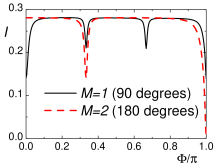
These results have been verified numerically and generalize those obtained previously for even, and odd . nos1 In particular, the total integrated transmittance for a half-filled ring with (so is shown in Fig. 3 for two positions of the drain lead, at (90-degree configuration) and (180-degree).
Some particular crossings satisfying Eq. (13) do not lead to dips because one of the matrix elements of Eq. (9) vanishes as a consequence of selection rules related with the total spin. For example, for the system of Fig. 3 the ground state with 4 electrons is a singlet, and one of the states with lowest energy for that cross at is a spin quartet which cannot be accessed destroying an electron from a singlet. Therefore, in this system, no depression of the conductance can be observed at equilibrium at zero temperature (for which only the ground state for any number of particles is accessible) at fluxes different from half a flux quantum (). At this flux a depression of the conductance is already expected for a non-interacting system. However, this is not the general case, and with increasing number of particles, states of low total spin are part of the ground state for any flux. Already for 5 particles, the 32 spin wave functions can be classified as one sextuplet with , one quadruplet for each of the four and five doublets, one for each of the non-equivalent . Addition of , in general favors the lowest total spin (some exceptions for low will be discussed below).
Note that for a half-filled system, the energy is zero for independent of the spin configuration (see Eq. (16)). Therefore addition of an antiferromagnetic exchange favors the lowest total spin: 0 (1/2) for an even (odd) number of particles.
To end this section we note that the spin velocity in the limit depends strongly on flux. It can be shown that for large , it is or for that leads to the minimum or maximum energy respectively.
IV Numerical results
In this section we present numerical results for the transmittance, obtained diagonalizing the ring using Davidson’s method david in order to obtain the Green’s functions, which replaced in Eqs. (5) and (6), give the transmittance. The systems studied are represented in Fig. 1. In contrast to previous work, Jagla ; meden ; nos1 ; julian we concentrate on the first peak in the transmittance as the gate voltage is decreased, which is experimentally accessible at equilibrium and low temperatures. For weakly coupled rings, this means that one has a system with electrons in the ring, a hole enters it from one of the leads, interacting with low-energy intermediate states with electrons, before leaving the ring at the other lead, while the ring returns to the ground state. Therefore the conductance gives information on the low-energy eigenstates of the ring and, as shown above for , on the separation of charge and spin degrees of freedom in a strongly interacting system. Similar results can be obtained for increasing gate voltage. In any case the electronic structure of the low-energy intermediate states is reflected.
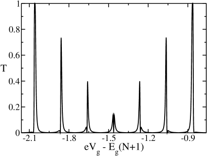
In Fig. 4 we show the transmittance for a half-filled ring of 6 sites connected with the leads at opposite sites (see Fig. 1 (a)) near a crossing of excited states with particles. The value of and the particular crossing were chosen so that according to the previous sections, a large negative interference is expected, leading to a depressed conductance. For , the crossing occurs at , but finite displaces it to smaller values. We have chosen a finite value of to break the degeneracy at between eigenstates with with total spin and for , as discussed at the end of the previous section. In any case, the states with do not contribute to the transmittance since they cannot be reached destroying an electron in the singlet ground state for 6 electrons.
Near the flux for which two 5-electron states with are degenerate, both corresponding peaks in the transmittance merge into one, therefore only one peak is seen for each flux (Fig. 4). Note that far from the crossing the width of each peak is given by Eq. (7) and increases with . Near the crossing, two poles of the Green’s functions dominate the transmittance as discussed in Section II C, and they contribute with opposite sign to it. As a consequence a strong depression of the conductance takes place at . In particular, Eqs. (5) and (6) indicate that the transmittance vanishes at for the value of the gate voltage at which the energies of both 5-electron states coincide with that of the ground state for 6 electrons. This might be an artifact of these expressions which are perturbative and are not expected to be valid near this point of triple degeneracy. lobos However, the physical origin of the depression of the conductance is clear and should be present in a more elaborate treatment.
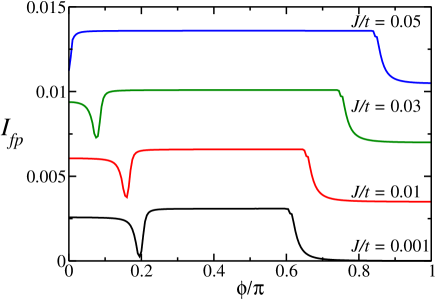
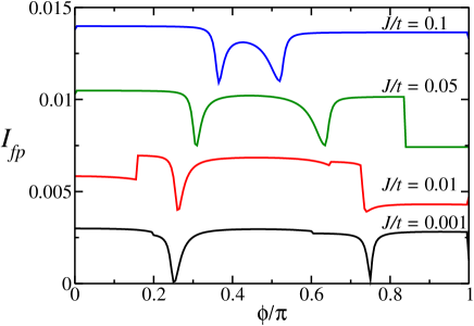
To quantify in a systematic way the relative intensity of the conductance that might be measured in an experimental setup, we integrate the transmittance given by Eqs. (5) and (6) in a window of gate voltage of width centered around the degeneracy point between the ground state for and electrons. This corresponds to the intensity of the first observable peak in the transmittance as the gate voltage is lowered. The result as a function of the applied magnetic flux for the same system of Fig. 4 is represented in Fig. 5. The curve is symmetric under change of sign of and therefore we show only the interval . For the dips should occur at , 0.6 and 1 according to Eq. (13). However, near 0.6 the ground state for 5 electrons changes from one of total spin to and the latter is not accessible destroying an electron in the 6-electron singlet ground state. Therefore, the transmittance vanishes at the gate voltage for which the ground state for 5 and 6 electrons have the same energy if . As a consequence, in the interval shown there is only one dip present. The position of this dip moves to lower values of with increasing . As might be expected the region of magnetic flux for which the ground state with 5 electrons has low total spin () increases with increasing antiferromagnetic exchange .
For a given flux, if the gate voltage is decreased further after the first peak in the transmittance is observed, the ground state of the ring has now 5 electrons and the next peak corresponds to the degeneracy of the ground states for 5 and 4 electrons. Fig. 6 illustrates this situation. For , Eq. (13) gives dips in the integrated transmittance for and 0.75. This agrees with the numerical calculations. The steps observed for intermediate values of are again due to jumps in the total spin of one of the ground states (for 4 or 5 electrons). In particular for for , the total spin of the 5-electron ground state jumps from for lower values of to for higher values of the flux.
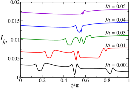
Finally in Fig. 7 we show the results for a half-filled ring of 7 sites with [see Fig. 1 (b)]. For low , the dips are expected at , 1/2 and 5/6 in close agreement with the numerical results. For increasing the dips tend to merge into one near .
Preparing the system with an odd number of electrons, like a half-filled system with an odd number of sites, has the advantage that more than one total spin is available for the intermediate states (0 and 1 in this case) and more dips are observable.
V Summary and discussion
We have shown for the first time that the equilibrium conductance through finite rings described by the model threaded by a magnetic flux, weakly coupled to conducting leads, at zero temperature, shows depressions at particular values of the flux. In general, for any strongly correlated model, these depressions are related with level crossings of excited states and the degree of interference depends on the wave vectors of these excited states, as described in Section II C. Previous results involved an integration over an energy window which included several excited states and this procedure could cast doubts on the validity of the behaviour for equilibrium conductance at zero or very low temperatures.
For the model and , using the exactly known energy spectrum of the isolated ring, we have determined the conditions under which dips in the integrated transmittance should occur, for different number of particles and sites of the ring . The position of the dips reflect the particular features of the spectrum for , in which the charge and spin degrees of freedom are separated at all energies, and not only asymptotically at low energies, as expected in Luttinger liquids. Haldane ; Schulz ; kv ; gia
In the equilibrium conductance at zero temperature, only the first peak in the transmittance as a function of gate voltage is accessible in an experimental setup. Depression of this conductance is expected in general at certain values of the applied magnetic flux, which are given by Eq. (13) for . The negative interference is more marked if the leads are connected at angles near 180 degrees. These results are confirmed by our numerical calculations. The positions of depressed conductance are modified as is increased in a way which seems difficult to predict. For moderate values of it is not clear for us, how to relate any particular position to a specific change in the spin quantum number. In addition, the number of these positions seems to decrease with increasing . This is in qualitative agreement with expectations based on the increase of the spin velocity, Jagla ; meden ; nos1 which should increase with . In particular, our results are valid for half-filled systems which we believe are easier to realize experimentally. Note, however, that due to particular selection rules explained at the end of Section III, the system size should be different than four to observe dips in the conductance. In any case and for any model, if the energy, wave vector and spin of the ground state is known when one particle is added to or removed from the system, the position of the dips can be predicted following the arguments of Section II C.
Due to selection rules related with total spin, more dips are expected for systems with an odd number of particles.
Our numerical results were based on an expression for the conductance first used by Jagla and Balseiro, Jagla which is perturbative in the coupling of the ring with the leads [Eqs. (5) and (6)]. This expression cannot capture non-perturbative effects, like the Kondo physics. lobos However, the physics of the depression of the conductance is present independently of the formalism used to calculate it. Nevertheless a more elaborate calculation of the conductance would be desirable. One possibility is to use numerical results for the ring to construct an effective model for the low-energy physics including the leads, and solve the model by non-perturbative methods. This approach has been followed in simpler problems. ihm ; lobos
Acknowledgments
This investigation was sponsored by PIP 5254 of CONICET and PICT 2006/483 of the ANPCyT. We are partially supported by CONICET.
References
- (1) D. Goldhaber-Gordon, H. Shtrikman, D. Mahalu, D. Abusch-Magder, U. Meirav, and M. A. Kastner, Nature 391, 156 (1998).
- (2) S. M. Cronenwet, T. H. Oosterkamp, and L. P. Kouwenhoven, Science 281, 540 (1998).
- (3) D. Goldhaber-Gordon, J. Göres, M. A. Kastner, H. Shtrikman, D. Mahalu, and U. Meirav, Phys. Rev. Lett. 81, 5225 (1998).
- (4) W.G. van der Wiel, S. de Franceschi, T. Fujisawa, J.M. Elzerman, S. Tarucha, and L.P. Kowenhoven, Science 289, 2105 (2000).
- (5) L. P. Kouwenhoven, F. W. J. Hekking, B. J. van Wees, C. J. P. M. Harmans, C. E. Timmering and C. T. Foxon, Phys. Rev. Lett. 65, 361 (1990).
- (6) Y. Oreg and D. Goldhaber-Gordon, Phys. Rev. Lett. 90, 136602 (2003).
- (7) R. Žitko and J. Bonča, Phys. Rev. B 74, 224411 (2006).
- (8) A. A. Aligia, K. Hallberg, B. Normand, and A. P. Kampf, Phys. Rev. Lett. 93, 076801 (2004).
- (9) G. B. Martins, C. A. Büsser, K. A. Al-Hassanieh, A. Moreo, and E. Dagotto, Phys. Rev. Lett. 94, 026804 (2005).
- (10) L. G. G. V. Dias da Silva, N. P. Sandler, K. Ingersent, and S. E. Ulloa, Phys. Rev. Lett. 97, 096603 (2006); ibid 99, 209702 (2007); L. Vaugier, A.A. Aligia and A.M. Lobos, ibid 99, 209701 (2007).
- (11) L. Vaugier, A.A. Aligia and A.M. Lobos, Phys. Rev. B 76, 165112 (2007).
- (12) F. D. M. Haldane, J. Phys. C 14, 2585 (1981).
- (13) H. J. Schulz, Int. J. Mod. Phys. B 5, 57 (1991).
- (14) K.-V. Pham, M. Gabay, and P. Lederer, Phys. Rev. B 61, 16397 (2000).
- (15) T. Giamarchi, Quantum physics in one dimension (Clarendon Press, Oxford, 2004).
- (16) K. Schönhammer in Strong Interactions in Low Dimensions, D. Baeriswyl and L. Degiorgi eds., Kluwer Academic Publishers, Dordrecht (2005); A. Yacoby, ibid
- (17) A. A. Aligia, Phys. Rev. B 69, 041101(R) (2004).
- (18) M. Ogata and H. Shiba, Phys. Rev. B 41, 2326 (1990).
- (19) J. Voit, Rep. Prog. Phys. 58, 977 (1995).
- (20) J. Voit, in Proceedings of the 9th International Conference on Recent Progress in Many-Body Physics, Ed. D. Neilson (World Scientific, Singapore, 1998).
- (21) C. Kim et al., Phys. Rev. Lett. 77, 4054 (1996).
- (22) C. L. Kane and M. P. A. Fisher, Phys. Rev. Lett. 76, 3192 (1996); R. W. Hill, C. Proust, L. Taillefer, P. Fournier and L. Greene, Nature 414, 711 (2001).
- (23) Q. Si, Phys. Rev. Lett. 78, 1767 (1997); Physica C 341, 1519 (2000).
- (24) E. Dagotto and T. M. Rice, Science 271, 618 (1996).
- (25) A. De Martino, R. Egger, K. Hallberg and C.A. Balseiro, Phys. Rev. Lett. 88, 206402 (2002); R. Egger and A. O. Gogolin, Phys. Rev. Lett. 79, 5082 (1997)
- (26) E. A. Jagla, K. Hallberg, and C. A. Balseiro, Phys. Rev. B 47, 5849 (1993).
- (27) C. Kollath, U. Schollwöck and W. Zwerger, Phys. Rev. Lett. 95, 176401 (2005)
- (28) A. Recati, P. O. Fedichev, W. Zwerger and P. Zoller, Phys. Rev. Lett. 90, 020401 (2002)
- (29) L. Kecke, H. Grabert, and W. Hausler, Phys. Rev. Lett. 95, 176802 (2005)
- (30) E. A. Jagla and C. A. Balseiro, Phys. Rev. Lett. 70, 639 (1993)
- (31) S. Friederich and V. Meden, Phys. Rev. B 77, 195122 (2008).
- (32) K. Hallberg, A. A. Aligia, A. Kampf and B. Normand, Phys. Rev. Lett. 93, 067203 (2004).
- (33) J. Rincón, K. Hallberg and A. A. Aligia, Phys. Rev. B 78, 125115 (2008)
- (34) P. W. Anderson, The Theory of Superconductivity in the High-Tc Cuprates, (Princeton University Press, Princeton, 1997).
- (35) Y. Meir and N. S. Wingreen, Phys. Rev. Lett. 68, 2512 (1992).
- (36) A. M. Lobos and A. A. Aligia, Phys. Rev. Lett. 100, 016803 (2008)
- (37) W. Caspers and P. Ilske, Physica A 157, 1033 (1989); A. Schadschneider, Phys. Rev. B 51, 10386 (1995).
- (38) Note that from Eqs. (10) and (11), adding to is equivalent to adding to the flux or 1 to all and so we are allowed to consider values of outside the “natural” interval .
- (39) E. R. Davidson, J. Comput. Phys. 17, 87 (1975); Comput. Phys. Comm. 53, 49 (1989)