Heat transfer mechanisms in bubbly Rayleigh-Bénard convection
Abstract
The heat transfer mechanism in Rayleigh-Bénard convection in a liquid with a mean temperature close to its boiling point is studied through numerical simulations with point-like vapor bubbles, which are allowed to grow or shrink through evaporation and condensation and which act back on the flow both thermally and mechanically. It is shown that the effect of the bubbles is strongly dependent on the ratio of the sensible heat to the latent heat as embodied in the Jacob number . For very small the bubbles stabilize the flow by absorbing heat in the warmer regions and releasing it in the colder regions. With an increase in , the added buoyancy due to the bubble growth destabilizes the flow with respect to single-phase convection and considerably increases the Nusselt number.
I Introduction
Thermal convection is an omnipresent phenomenon in nature and technology. The idealized version thereof is Rayleigh-Bénard (RB) convection – a single-phase fluid in a closed container heated from below and cooled from above. A key question is the dependence of the heat transfer rate (as measured by the Nusselt number) for given temperature difference between the hot bottom and cold top plate (i.e., Rayleigh number), given fluid (i.e., Prandtl number), and given aspect ratio. In the last two decades there has been tremendous progress on this and related questions by experiment, theory and numerical simulation, see kad01 and ahl09 for a recent review. Most of the work focused on RB convection for single-phase flow. Various situations in the process and energy industries, however, involve convection in the presence of phase change, e.g. condensing vapors and boiling liquids.
The effectiveness of boiling as a heat transfer mechanism has been known for centuries and the process has formed the object of a very large number of studies dhi98 . Most of the focus has been on the process by which the high thermal resistance opposed by the visco-thermal layer adjacent to the hot surface is decreased by the vapor bubbles, the two main mechanisms believed to be micro-convection and latent heat transport. Another significant effect of the bubbles, however, is to promote strong convective currents in the liquid, thus helping remove the heated layer near the hot wall. This aspect of the process forms the object of the present study.
In an actual experiment all the processes occur at the same time and it is next to impossible to separately quantify their relative importance. Numerical simulation appears to be a promising tool for this purpose. Ideally, a simulation should be able to resolve individual bubbles and follow their evolution but, with the present capabilities, only so few bubbles can be simulated to this level of detail that it would be very difficult to draw conclusive results bun02a ; bun02b ; esm05 ; MukherjeeDhir04 . Therefore one has to fall back on point-bubble models in which the interaction of the individual bubbles with the surrounding liquid is parameterized. This approach has proven valuable in the study of turbulence in particle-laden flows (see e.g. Elg ; Boi98 ; FerranteElghobashi03 ), in liquids with gas – rather than vapor – bubbles cli99 ; maz03a ; maz03b and for Taylor-Couette flow with microbubbles inducing drag reduction sug08b .
Many important physical mechanisms have been elucidated by these means and one may therefore hope that similar insights might be achieved by extending this line of research accounting for phase change processes, and the accompanying bubble growth and collapse, in a similar way. Thus, to the fluid-mechanic bubble-liquid interaction model used in our earlier work (maz03a ; maz03b ), we add here models for the heat transfer and phase change between the bubbles and the surrounding liquid along the lines of Refs. leg98b ; iva04 .
The standard single-phase RB convection under the Boussinesq approximation is controlled by the Rayleigh number
| (1) |
where and are the temperatures of the hot (bottom) and cold (top) plate, respectively, is the height of the convection cylinder, the gravitational acceleration, the thermal diffusivity of the liquid, its kinematic viscosity, and the isobaric thermal expansion coefficient). The Prandtl number is defined as
| (2) |
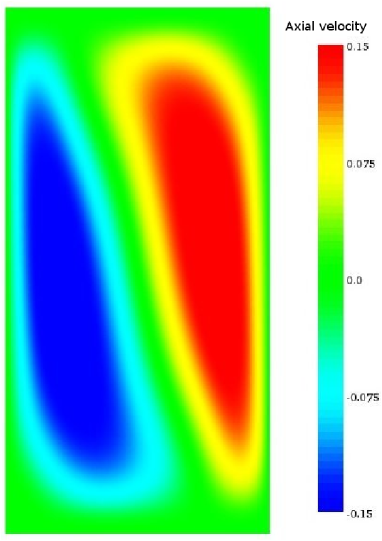
and the aspect ratio of the cylinder as the ratio of the diameter to the height. In this paper we consider convection for which, without bubbles, and = 1.75 (water at ); the aspect ratio is 1/2 and the cell is cylindrical. With these parameter values, in the absence of bubbles, there is a convection roll with fluid rising along one side of the cell and descending along the opposite side (see figure 1); the Nusselt number has the value 4.75.
Vapor bubbles introduce a crucial new parameter, the Jacob number
| (3) |
in which is the latent heat, and the vapor and liquid density, respectively, the liquid specific heat and the saturation temperature of the liquid. With the parameter values used in this study, hydrostatic pressure variations are not sufficient to cause a significant change of , which therefore is taken as a constant equal to the average of the hot and cold plate temperatures. Physically, represents the ratio of the sensible heat to the latent heat. A very small Jacob number may be thought of as a very large value of the latent heat, which will tend to limit the volume change of the bubbles due to evaporation or condensation.
For the latent heat is effectively infinite and bubbles cannot grow or shrink; they maintain their initial diameter at nucleation, which we take to be 25 m. Another control parameter in our model is the total number of bubbles in the cylinder. Though in real systems this number will fluctuate in time somewhat, here we take it as constant: Whenever a bubble reaches the top of the cylinder and is removed, a new bubble of the standard initial size (m) is nucleated at the bottom plate at some random position.
II Model
We study the problem in the standard Boussinesq approximation augmented by the momentum and energy effects of the bubbles, treated as points. When the volume occupied by the bubbles is very small, the liquid continuity equation retains the standard incompressible form
| (4) |
in which u is the liquid velocity field. The momentum equations is
| (5) |
where is the convective derivative, and are the pressure and temperature, and the dynamic viscosity. The effect of the bubbles has been approximated in the standard way by modeling them as point-like sources of momentum, which is adequate when the volume fraction is small and the bubble radius is smaller than the fluid length scales (see e.g. maz03b ).
The position of the -th bubble is denoted by and the force that it applies on the liquid is modelled as (see e.g. max94 ; maz03b )
| (6) |
in which is the radius of the -th bubble and the liquid acceleration is evaluated at the position of the bubble. A similar term multiplied by the vapor, rather than the liquid, density has been neglected here.
The liquid energy equation takes the form
| (7) |
where is the liquid thermal conductivity and is the energy source or sink due to phase change of the -th bubble. We model the thermal exchange between the -th bubble and the liquid by means of a heat transfer coefficient and write
| (8) |
where is the liquid temperature evaluated at the position of the -th bubble. In writing this relation we have used the fact that, for moderate temperature differences, phase change is slow and the bubble surface remains essentially at saturated conditions (see e.g. YangProsperetti08 ).
The expressions (6) and (8) and the use of point sources of momentum in (5) and of energy in (7) assume that the bubbles interact only through the average fields but not directly, which is a reasonable approximation at the vapor volume fractions considered here (see e.g. maz03a ; maz03b ).
Part of the system energy is carried by the bubble phase. If denotes the energy of a single bubble, the bubble number density and the bubble velocity, conservation of this component of the system energy is expressed by
| (9) |
where the small contribution has been neglected. Adding (7) and (9) gives an equation for the balance of the total system energy, namely
| (10) |
With the neglect of the vapor mass, the equation of motion for each bubble balances added mass, lift, and buoyancy,
| (11) |
in which , , and are the added mass, lift and drag coefficients, respectively. The uncertainty with which many of the terms of this equation are known is well appreciated in the literature (see e.g. mag00 or our own work nie07 ). Moreover, due to interaction with the wake, there might be history forces which have been neglected in (11) mei94 ; leg98 ; mag98 . Nevertheless, as written, the equation captures the basic effects of drag, buoyancy, and added mass which dominate the bubble-liquid interaction. After some rearrangement, the equation becomes
| (12) |
The bubble radius is calculated by balancing the latent heat associated to evaporation or condensation with the heat exchanged with the liquid
| (13) |
Since the bubble is assumed to be at saturation, is a constant and this equation can be simplified to the form
| (14) |
in which .
In order to complete the mathematical formulation of the problem, definite choices must be made for several quantities. Since our bubbles are small and therefore will not deform very much, we take , the standard potential-flow value for a sphere (see e.g. bat67 ), independent of the Reynolds number and of non-uniformities of the flow mag95 ; aut87 ; riv91 ; cha95 . The inviscid calculation of aut87 gives the same value for the lift coefficient; this value appears to be a reasonable estimate even at low to moderate Reynolds number (see figure 17 of leg98 ). We model the drag coefficient as suggested by mei92 ; mei94 ,
| (15) |
in which is the bubble Reynolds number.
We express the heat transfer coefficient in terms of a single-bubble Nusselt number
| (16) |
The dependence of on the parameters of the problem is complicated and has been studied by several authors (see e.g. leg98b ; iva04 ). In order to make progress we are forced to introduce some simplifications. The analysis of leg98b shows that, as a function of the Péclet number
| (17) |
there are essentially two regimes. At low , is approximately independent of and only depends on the Jacob number (3). We call this value The functional relationship in this regime has been variously parameterized by different authors. Reference leg98b proposes a general form
| (18) |
For the function Ref. lab64 (corroborated by the more recent results of Ref.iva04 ) proposes
| (19) |
with which (18) becomes
| (20) |
For very large Péclet numbers, heat transfer is dominated by convection and the result is ruc59
| (21) |
We combine these two asymptotic forms in a way that smoothly interpolates between them:
| (22) |
where is determined by fitting the results of Refs. ruc59 and iva04 and the crossover Péclet number , defined by , is . The relation (22) is shown as a function of for = 1 and 10 in figure 2. These results can be compared with the corresponding ones presented in figure 3 of leg98b and are seen to provide an accurate representation of them.

III Nusselt number
If the total energy equation (10) is averaged over time and integrated over the cylinder volume we find
| (23) |
where the subscript 3 denotes the vertical direction and the time and area average. In deriving this relation we have used the no-slip condition for the liquid phase and the assumed adiabaticity of the lateral walls. The bubble velocity on the bottom and top plates must account for the injection and removal of bubbles and therefore cannot be taken to vanish. A similar treatment of the bubble energy equation (9) gives
| (24) |
where is the radius of the cylinder. The summation in the last term is over all the bubbles contained in the system and the average is over time. Using (24), (23) can equivalently be written as
| (25) |
which expresses the obvious fact that any difference between the heat conducted out of the bottom plate and into the top plate is due to the energy stored in the bubbles.
In single-phase natural convection the conventional definition of the Nusselt numbers and at the hot and cold plates is
| (26) |
In the single-phase case this quantity may be considered as a total dimensionless heat flux, but this interpretation would be incorrect here as it disregards the effect of the bubbles. Here the proper quantity to be regarded as the total dimensionless heat flux would be
| (27) |
which, by (23), satisfies
| (28) |
as expected. However, since the point of this paper is to show the impact of the bubbles on what would be considered the heat flux in single-phase convection, it is preferable to present our results in terms of rather than .
The definitions (26) lead to
| (29) |
Separate expressions for and can be found by using another relation which can be derived by multiplying (7) by and integrating over the volume of the cylinder with the result
| (30) |
in which denotes a time and volume average; in the following we refer to as the average Nusselt number. By using this relation and (29) we have
| (31) |
and
| (32) |
The dimensionless heat fluxes can be reconstructed by noting that, since bubbles are injected with a small velocity and a small radius, the first term in the right-hand side of (24) is much smaller than the second one and therefore, approximately,
| (33) |
Thus, at the hot plate,
| (34) |
and, at the cold plate,
| (35) |
in the last step of which use has been made of (29).
Just as the Nusselt number, the expressions for the kinetic and thermal dissipations and of standard single-phase natural convection are also affected by the bubble contribution to the liquid energy equation. These modified expressions are derived in the Appendix.
IV Numerical methods
Equations (5) and (7) have been written in cylindrical coordinates and discretized using staggered second-order-accurate finite difference schemes. The resulting algebraic system is solved by a fractional step method with the advective terms treated explicitly and the viscous terms computed implicitly by an approximate factorization technique (see VeOr for details). The Poisson equation that enforces the flow incompressibility is solved by a direct procedure which relies on trigonometric expansions in the azimuthal direction and the FISHPACK package swartz for the radial and axial directions for which, therefore, a non-uniform mesh distribution can be used. The grid is non-uniform in the radial and axial directions and clustered towards the boundaries to adequately resolve the viscous and thermal layers. Following Verzicco and Camussi Verz3 , we used a grid with points, respectively, in the azimuthal, radial and axial directions after having verified that this resolution is sufficient for the present Rayleigh and Prandtl numbers.
Although the code can handle high-order multistep schemes, the time advancement of the solution has been carried out by a simple second-order Adams-Bashforth procedure. For this problem, the most severe limitation on the time step size is imposed by the bubble relaxation time which, especially for the smallest bubbles, is much more stringent than the flow stability condition.
The only relevant change with respect to the method described in Verz3 is the presence of bubble-induced momentum and thermal forcings in the governing equations. The forcing due to each bubble is located at its center and therefore, when (5) and (7) are discretized, it has to be replaced with an equivalent system of forcings at the grid nodes. For this purpose, since in a staggered grid arrangement the momentum cells in the three directions are all different, the force (6) exerted by the bubble is first decomposed into its radial, azimuthal and vertical components. Each one of these components is then distributed by suitable weighing among the 8 vertices of the surrounding momentum cell in the same direction. For example, for a radial force component at a position , , , with , and the grid spacings and , the portion attributed to the node is
| (36) |
The system of 8 forces thus obtained produces the same net resultant and couple as the original bubble force. The same strategy has been used for the thermal forcing so that the total amount of heat that each bubble exchanges with the liquid is preserved.
The bubble trajectory is computed using the Adams-Bashforth scheme for position and the Crank-Nicholson scheme for velocity. This latter implicit scheme avoids the numerical instability induced by the fast dynamics of the smallest bubbles. Equation (14) for the bubble radius is integrated explicitly.
The numerical solver has been validated by monitoring the temporal evolution of a single bubble in a quiescent flow without a thermal field. Furthermore, our results have been compared with the theoretical prediction of the lateral force induced on a spherical bubble rising with a constant velocity in a viscous fluid near a vertical cylindrical wall. We followed the theoretical method of ref. Shi79 using the free-slip boundary condition for the bubble surface instead of the no-slip condition used for a rigid particle. Another test of the numerical method and its implementation is offered by a comparison of the numerical results for the two sides of (29). Such a comparison is shown for a typical case in Fig. 3.

V Implementation
From the numerical point of view, a significant practical difficulty of the present problem is the large difference between the flow time scale and the times over which bubbles grow and collapse. In order to have reasonable execution times of our computer code it has been necessary to limit this difference by adopting a small cylinder size; we have taken a height mm and a diameter mm. Furthermore, in order to limit the number of spatial cells necessary to resolve the flow it is necessary to limit the Rayleigh number, which can be achieved by taking a small temperature difference; we take K. With these values and the physical properties of water at 373 K, we have . Since , the hot plate is 0.125 K hotter than the saturation temperature, which in reality would not be a superheat sufficient to nucleate bubbles. This is another respect in which our model deviates from reality. On the other hand, since our focus here is the bubble effect on the thermal convection, rather than the actual heat removal from the plate due to bubble formation, the compromise that is forced on us is less damaging than it might be in a study of boiling heat transfer.
The calculation is started without bubbles and run until the steady state shown in figure 1 is reached. At this point 25 m-diameter bubbles are introduced randomly throughout the volume of the cylinder attributing to each one the local liquid velocity. From this point on, whenever a bubble reaches the top plate, it is removed and a new 25-diameter bubble is introduced at a random position on the bottom plate. The new bubble is placed at a height above the plate equal to its radius and it is given the local liquid velocity. Bubbles reaching the lateral vertical wall of the cylinder are assumed to bounce elastically.
In order to avoid possible numerical problems due to the disappearance or excessive growth of bubbles, we have imposed artificial limits on the minimum and maximum bubble diameters equal to 0.82 m and 258 m respectively. We found however that these limits are never approached in our simulations. Since bubbles never condense completely, the total number of bubbles is constant in time.
VI Results
Since bubbles tend to grow in volume in hotter liquid region, thus aiding buoyancy, and to condense in colder regions, they have a de-stabilizing effect on natural convection. These effects are clearly the stronger the larger the volume change. As explained before, in the present model this feature can be controlled by controlling the Jacob number (3). A very small Jacob number may be thought of as a very large latent heat, which will tend to limit the volume change of the bubble, while, conversely, a large Jacob number would enhance the destabilizing effect.
While this is the major effect, there are other minor ones which operate in the opposite direction. For example, bubbles in a hot liquid region, for which , will tend to cool the liquid by absorbing heat, and conversely in a colder liquid region. If is very small so that the bubble is prevented from growing appreciably, this process tends to eliminate the very temperature differences which drive the natural convection in the first place. All other things being equal, the break-even point between increased buoyancy due to bubble expansion and decreased liquid buoyancy due to the bubble-induced cooling will be for that value of the Jacob number at which the thermal expansion of the bubble equals the added weight of the liquid due to the increased density. It will be seen from our results that this balance occurs for very small so that, in most practical situations, the balance will tip in favor of the enhanced buoyancy effect.
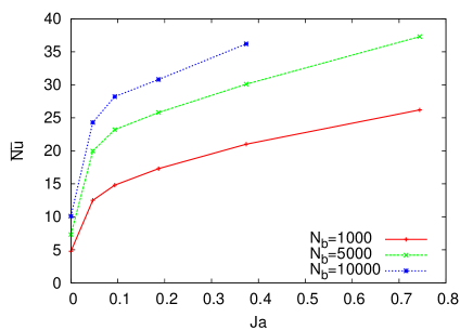
Figure 4 shows the effect on the average Nusselt number , defined in (30), of adding 1,000, 5,000 and 10,000 bubbles to the basic single-phase RB flow; here, as in all the results shown, the Rayleigh number is and = 1.75. Figure 5 shows the fraction of the bubble contribution
| (37) |
to the average Nusselt number . The remaining fraction of the Nusselt number is accounted for by conduction and pure convection, i.e. the first two terms in the right-hand sides of (31) and (32). In both figures the horizontal axis is the Jacob number, which we use as a control parameter to investigate the effect of the added bubble buoyancy.
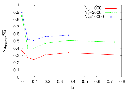
For = 0 the bubbles maintain their initial diameter at injection at the plate (25 m) but, because they are kept at , they cool the hotter liquid regions and heat up the cooler ones. As noted before, this behavior tends to stabilize the RB convection and is responsible for the fact that, while in the absence of bubbles the flow consists of an annular roll with an approximately horizontal axis (Fig. 1), the addition of bubbles changes it to a toroidal roll with a vertical axis. Because of this stabilizing effect, the cooling/heating operated by the bubbles accounts for a large fraction of the total heat transported and, indeed, it can be seen from Fig. 5 that the bubble contribution (37) is very large, up to about 90% of the total for the 10,000 bubble case.
As is increased, the Nusselt number increases very rapidly at first (Fig. 4) due to the increased convection caused by buoyancy. As a consequence, the fraction of the total Nusselt number due to the bubbles (Fig. 5) undergoes a steep decline. With further increases of , the Nusselt number keeps growing but at a more moderate rate. The minimum around = 0.1 observed in figure 5 is due to a change of the flow structure as described later.
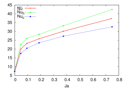
Figure 6 shows the Nusselt numbers computed at the top and bottom of the cylinder and their average for 5,000 bubbles; the behavior for the other bubble numbers is very similar. As shown by (29), the difference is due to the heat exchanged between the bubbles and the liquid. As the Jacob number begins to increase, the energy absorbed by each bubble per unit time increases because of a direct increase in the heat transfer coefficient of each individual bubble (see Eq. 20), and an increase in the convective component of the bubble heat flux caused by the faster rise velocity of a larger bubble (Eq. 21). The moderation in the rate of growth of at larger is probably due to the increasing bubble rise velocity which limits their residence time in the cylinder.
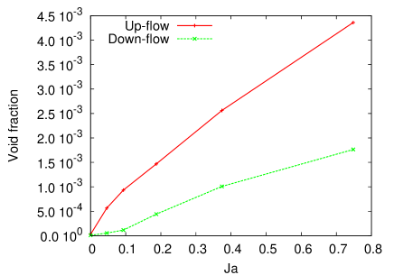
By calculating the volume of bubbles located in regions of positive and negative vertical liquid velocities we can look in detail at the effect of the increased buoyancy. Figure 7 shows the time- and volume-averaged vapor volume fractions for 5,000 bubbles as a function of the Jacob number. The results for the other cases are similar, with smaller void fractions for 1,000 bubbles (for = 0.35, approximately 0.02% and 0.08%), and larger ones for 10,000 bubbles (for = 0.35, approximately 0.16% and 0.36%). It is seen that the void fraction in the upflow regions is consistently much larger than in the downflow regions, thus providing strong evidence for the expected destabilizing effect of the buoyancy provided by the bubbles.
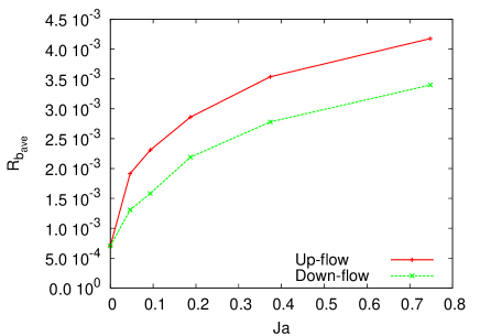
The void fraction reflects the combined effect of bubble number and bubble volume and it is interesting to consider these two contributions separately. The volume- and time-averaged bubble radius , defined by
| (38) |
is shown in Fig. 8 as a function of the Jacob number for the case of Fig. 7 with 5000 bubbles. As expected, the bubble size increases markedly with the Jacob number and it tends to be somewhat larger in the hotter liquid regions. The time- and volume-averaged fractions of the total bubble number in the upflow and downflow regions, shown in Fig. 9, indicates a strong tendency for bubbles to be in the hotter liquid regions, which is mostly responsible for the much larger void fraction in the rising liquid. This effect is probably due to fact that the newly injected bubbles at the hot plate tend to be swept up into the warm liquid by the convection current.
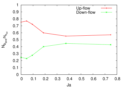
The results of Fig. 9 for the bubble numbers show that the difference between the fractions of bubbles in the upflow and downflow regions is very large for small Jacob numbers and tends to decrease as increases. This behavior can be understood looking at the change in the flow structure.
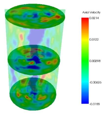
Without bubbles, the cylinder is occupied by a single convective roll which rises along one side and descends along the opposite side (Fig. 1). A picture of the flow for the 5,000 bubbles, case is shown in Fig. 10 where one vertical and three horizontal cross sections color-coded with the vertical velocity field are displayed. The blue structure in the proximity of the cylinder axis is the descending region of a toroidal vortex, while the remaining green areas are those where the liquid rises, mostly with a smaller velocity, except for a few faster zones (yellow and red). It can be seen here that the volume occupied by the rising liquid is much greater than that occupied by the descending liquid, and this circumstance offers a likely explanation of the much smaller fraction of bubbles in the latter.
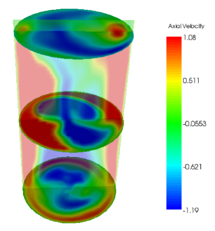
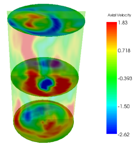
If the Jacob number is increased to (Fig. 11), the toroidal circulation is reinforced with a marked increase in the maximum rising and descending velocities (note that the color scales in these figures are not the same). For a still larger Jacob number, (Fig. 12) the flow has changed back to a circulation rising along one side of the cylinder and descending along the opposite one reminiscent of the single-phase pattern of Fig. 1. Now the volumes occupied by the two streams are more balanced and the difference between the number of bubbles in the upflow and downflow regions is smaller, as seen in Fig. 9, although the bubble fraction in the upflow is still larger than in the downflow.
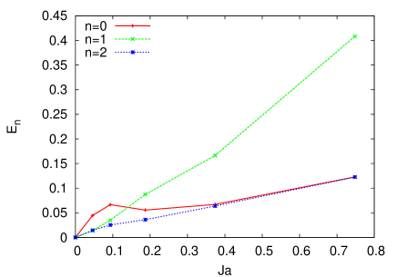
These qualitative observations on the flow structure can be made quantitative by an analysis of the distribution of the liquid kinetic energy among different Fourier modes in the angular direction. We define the portion of the kinetic energy pertaining to mode by
| (39) |
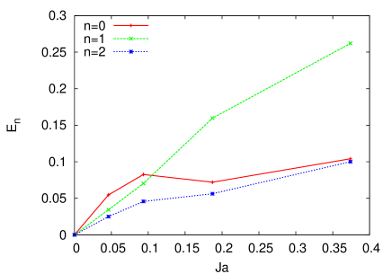
where is the -th Fourier coefficient (in angular direction) of the vector velocity field. The mode is axisymmetric and corresponds to a toroidal circulation symmetric about the vertical axis of the cylinder; is a single vortex around an approximately horizontal axis, and the higher modes give further information on the details of the distribution of the flow over the cross section of the cylinder. Results for the = 0, 1 and 2 modes are shown in Figs. 13 and 14 for 5,000 and 10,000 bubbles, respectively; the time averaging was carried out over the entire duration of the two-phase simulation. The values for are very small, but non-zero. It is seen here that, for zero or small Jacob number, most of the kinetic energy is in the toroidal mode = 0 which, for 5,000 bubbles, reaches a maximum at , which is the case shown in Fig. 11. For larger values of , the energy in the mode decreases while that in the mode rapidly increases giving rise to the flow structure exemplified in Fig. 12.
VII Summary and conclusions
In this paper we have presented a simple model to simulate the effect of phase change and two-phase flow on natural convection. While, for the reasons given in section V, the results must be considered as preliminary, we have found that the addition of bubbles has a profound effect on the flow structure and on the Nusselt number. Bubbles that are prevented from growing by artificially maintaining the Jacob number equal to zero (corresponding to an infinitely large latent heat of vaporization) tend to short-circuit temperature non-uniformities and to stabilize the convective motion. As the Jacob number is increased, the added buoyancy due to the bubble growth rapidly increases the circulation and the heat transport. As the Jacob number is increased further, bubble growth is rapid, the residence time short, and the rate of growth of the Nusselt number slows down. Correspondingly with the increasing Jacob number, the structure of the convective flow in the cylinder undergoes significant changes.
Acknowledgements: The authors thank K. Sugiyama for various discussions and code validation calculations. We moreover acknowledge SARA, Amsterdam, for supplying us with CPU time.
Appendix A Exact relations for the kinetic and thermal dissipations and
Upon multiplying the momentum equation (5) by u and averaging over the cylinder volume and time, we find, by the no-slip condition on the cylinder walls,
| (40) |
The term can be eliminated in terms of the single-phase Nusselt number at the hot base of the cylinder, given by (31), to find
| (41) | |||||
in which is the volume of the cylinder. Alternatively, in terms of the Nusselt number at the cold top of the cylinder,
| (42) | |||||
The thermal dissipation is defined in terms of
| (43) |
as . An expression for this quantity may be readily obtained by multipling the energy equation by and averaging over the cylinder volume and time to find
| (44) | |||||
where we have used the assumed insulation of the lateral walls and the fact that at the bottom and top of the cylinder. The temperature gradients can be eliminated in terms of the Nusselt numbers to find
| (45) |
which replaces the well-known relation of single-phase RB convection.
References
- (1) L. P. Kadanoff, Phys. Today 54, 34 (2001).
- (2) G. Ahlers, S. Grossmann, and D. Lohse, Rev. Mod. Phys. 81, y (2009).
- (3) V. Dhir, Ann. Rev. Fluid Mech. 30, 365 (1998).
- (4) A. Mukherjee and V. Dhir, J. Heat Transfer 126, 1023 (2004).
- (5) B. Bunner and G. Tryggvason, J. Fluid Mech. 466, 17 (2002).
- (6) B. Bunner and G. Tryggvason, J. Fluid Mech. 466, 53 (2002).
- (7) A. Esmaeeli and G. Tryggvason, Phys. Fluids 17, 093303 (2005).
- (8) S. Elghobaschi and T. G. C., J. Fluid Mech. 242, 655 (1992).
- (9) M. Boivin, O. Simonin, and K. Squires, J. Fluid Mech. 375, 235 (1998).
- (10) A. Ferrante and S. Elghobashi, Phys. Fluids 15, 315 (2003).
- (11) E. Climent and J. Magnaudet, Phys. Rev. Lett. 82, 4827 (1999).
- (12) I. Mazzitelli, D. Lohse, and F. Toschi, Phys. Fluids 15, L5 (2003).
- (13) I. Mazzitelli, D. Lohse, and F. Toschi, J. Fluid Mech. 488, 283 (2003).
- (14) K. Sugiyama, E. Calzavarini, and D. Lohse, J. Fluid Mech. 608, 21 (2008).
- (15) J. Magnaudet, J. Borée, and D. Legendre, Phys. Fluids 10, 1256 (1998).
- (16) O. E. Ivashnyov and N. N. Smirnov, Phys. Fluids 16, 809 (2004).
- (17) M. R. Maxey, E. Chang, and L. Wang, Appl. Mech. Rev. 46, 6 (1994).
- (18) B. Yang and A. Prosperetti, J. Fluid Mech. 601, 253 (2008).
- (19) J. Magnaudet and I. Eames, Annu. Rev. Fluid Mech. 32, 659 (2000).
- (20) E. A. van Nierop et al., J. Fluid Mech. 571, 439 (2007).
- (21) R. Mei, J. F. Klausner, and C. J. Lawrence, Phys. Fluids 6, 418 (1994).
- (22) D. Legendre and J. Magnaudet, J. Fluid Mech. 368, 81 (1998).
- (23) J. Magnaudet and D. Legendre, Phys. Fluids 10, 550 (1998).
- (24) G. K. Batchelor, An Introduction to Fluid Dynamics (Cambridge University Press, Cambridge, 1967).
- (25) J. Magnaudet, M. Rivero, and J. Fabre, J. Fluid Mech. 284, 97 (1995).
- (26) T. R. Auton, J. Fluid Mech. 183, 199 (1987).
- (27) M. Rivero, J. Magnaudet, and J. Fabre, C.R. Acad. Sci. Paris II 312, 1499 (1991).
- (28) E. J. Chang and M. R. Maxey, J. Fluid Mech. 303, 133 (1995).
- (29) R. Mei and J. Klausner, Phys. Fluids A 4, 63 (1992).
- (30) D. A. Labuntsov, B. A. Kolchygin, E. A. Zacharova, and L. N. Vladimirova, Teplofiz. Vys. Temp. 2, 446 (1964).
- (31) E. Ruckenstein, Chem. Eng. Sci. 10, 22 (1959).
- (32) R. Verzicco and P. Orlandi, J. Comp Phys. 123, 402 (1996).
- (33) P. N. Swartztrauber, SIAM J. Numer. Anal. 11, 1136 (1974).
- (34) R. Verzicco and R. Camussi, J. Fluid Mech. 477, 19 (2003).
- (35) M. Shinohara and H. Hashimoto, J. Phys. Soc. Japan 46, 320 (1979).