Efficient Raman amplification into the PetaWatt regime
Abstract
Raman amplification of a short laser pulse off a long laser beam has been demonstrated successfully for moderate probe intensities ( W/cm2) and widths ( micron). However, truly competitive intensities can only be reached if the amplification process is carried out at much higher probe intensities ( W/cm2 after amplification) and widths ( mm). We examine the opportunities and challenges provided by this regime through the first 2-dimensional particle-in-cell simulations using wide pulses. A parameter window is identified in which a 10 TW, 600 m wide, 25 ps long laser pulse can be efficiently amplified to 2 PW peak intensity.
pacs:
52.38.-r, 42.65.Re, 52.38.Bv, 52.38.HbThere has been a great deal of interest in obtaining ultra-high laser intensities by using the technique of Raman amplification in a plasma shvets98 ; shvets99 . The main reason for using a plasma is that it can tolerate much higher laser intensities ( W/cm2 or more) than solid state devices that are commonly used in the Chirped Pulse Amplification (CPA) scheme (up to W/cm2). Extensive analytical shvets98 ; shvets99 ; malkin00 ; malk00pop ; tsid00 ; tsid02 ; balakin03 ; ersfeld , numerical leehj ; mardahl ; mshur04 ; clark05 ; balakin05 ; mshur05 ; weber and experimental ping04 ; dreher04 ; cheng05 ; kirkw07 research recently culminated in the experimental demonstration of Raman amplification of a of a W/cm2 probe pulse to W/cm2 off a W/cm2 pump pulse in a 1 mm long, 80 m wide plasma channel ren07 . Based on these results, it has been predicted that the Raman amplification scheme can be extended to produce laser pulses at much higher intensities than currently available from solid-state lasers. Eventually, this should lead to Raman amplification of cm-wide laser beams having m wavelength to - W/cm2 malkin00 , which are to be focused down to m-wide spots to reach peak intensities of - W/cm2 fisch03 ; malkin05 ; malkin07 , approaching the Schwinger limit.
In order to reach such extreme intensities, the Raman amplification scheme needs to be extended from its current dimensions (1 mm long, 50-80 m wide, W/cm2 pump, W/cm2 final probe) to a length and width of 1-10 cm each, a pump intensity of - W/cm2 and a final probe intensity of - W/cm2. Quite significant extensions of the scheme are necessary in any event, to investigate whether Raman amplification will be able to compete with recent developments in solid-state laser technology, e.g. OPCPA ross97 ; chekhlov07 . However, there are few results in the literature on the feasibility of such extensions shvets99 ; clark05 . The existing analytic theory is one-dimensional and only weakly non-linear shvets98 ; shvets99 ; malkin00 . Most numerical simulations have been performed in one dimension and with envelope models for the laser pulses mshur04 ; balakin05 ; mshur05 rather than solving the full set of Maxwell’s equations leehj ; clark05 ; weber . Only a few 2-D particle-in-cell (PIC) simulation results are available, and these only deal with narrow pulses (4-6 m) and short propagation distances ( mm) mardahl . Experiments whose parameters go beyond that of Ren et al. ren07 have yet to be conducted. In short, while there is a strong need for any results concerning the extension of Raman amplification to greater propagation lengths, pulse widths and pulse intensities, such results have not been available until now.
In this paper we present the results of a series of multi-dimensional particle-in-cell simulations that have been conducted to investigate the possibilities for extending the Raman amplification scheme. These simulations have been carried out at greater propagation lengths, pulse widths and pulse intensities than have been studied in previous publications, to investigate the effects of these on the amplification process. A multitude of nonlinear effects have been encountered, such as probe saturation due to Raman forward scattering (RFS) and wakefield generation, breaking of the RBS Langmuir wave that couples pump and probe, parasitic pump RBS, and transverse filamentation of both pump and probe pulses in 2-D simulations. For each simulation we have also determined the efficiency of the energy transfer from pump to probe, and found that this efficiency is critically dependent on a number of parameters. Controlling the efficiency is vital for the success of the scheme, as most predictions regarding extreme probe intensities are based on the assumption of near-perfect efficiency. Although these issues narrow the parameter window for effective Raman amplification down considerably, we have been able to identify a parameter regime in which a 10 TW, 600 m wide, 25 ps long laser pulse can be efficiently amplified to 2 PW peak intensity, as discussed below.
For the simulations, we have used the 1-D and 2-D versions of the particle-in-cell (PIC) codes XOOPIC oopic and OSIRIS 2.0 osiris . XOOPIC has been used to study Raman amplification before leehj ; mardahl and can launch a backward-moving long pump pulse from the leading edge of a moving window. This allowed us to use a small moving window following the probe pulse while it interacts with a long pump, thus concentrating on the evolution of the probe. On the other hand, OSIRIS is fully parallelized, so it could be used to study the entire evolution of the pump pulse during its propagation through the plasma column, before meeting the probe pulse. Where possible, we have used the simulation results of both codes for mutual verification, thus ensuring their correctness.
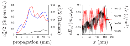
To investigate the effect of a longer interaction length, we have performed a series of 1-D simulations using both XOOPIC and OSIRIS. Parameters of these simulations were as follows. Pump and probe amplitudes were , pump wave length nm, , the pump was “infinitely” long while the initial probe duration was 50 fs. The results are depicted in Figure 1. The left frame shows the evolution of the probe intensity for several typical amplification scenarios. It was found that the probe amplification starts off in a promising way, but usually saturates after up to 5 mm of propagation, when its intensity becomes sufficient to trigger nonlinear effects (red and blue curves). Saturation was only absent when the energy transfer was so inefficient that the probe was not properly amplified (black curve). Saturation happens for the following reasons: probe RFS (which scatters energy away from the matching probe frequency to non-matching frequencies that cannot contribute to the Raman amplification process), modulational instability of the probe and subsequent wakefield generation by the probe (which combine to deplete the energy of the probe). The effects of RFS and probe modulation on Raman amplification are displayed in the right frame of Figure 1. It is found that the probe leaves a wakefield behind, while its envelope is modulated on the wave length of the wakefield. RFS and probe modulation therefore need to be avoided at all cost. This can be done by decreasing the plasma density so the probe length is shorter than and RFS growth is inhibited, as discussed below. There is no real cure for the saturation of the probe; it simply limits the intensity to which the probe can be Raman amplified, as already predicted in Ref. malk00pop . In our simulations, we found that efficient probe amplification is possible until the probe intensity is about 200 times that of the pump. Beyond that, saturation sets in, the efficiency of the process drops and the probe envelope deteriorates.
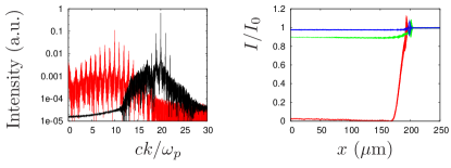
In addition, it has been found that the pump may suffer from parasitic instabilities as it penetrates the plasma column even before meeting the probe, mostly parasitic RBS, as illustrated in Figure 2, left. Here, the wave number spectra of pump pulses having are shown after traversing a 5 mm long plasma column at , 20. At the higher density, the pump’s spectrum shows many side bands which are not much below the intensity of the fundamental peak. This renders the pump useless for Raman amplification. At the lower density, the pump’s spectrum shows fewer side bands at lower relative intensity, indicating that the pump is still suitable for amplification in this case. Thus, lowering the plasma density will mitigate both probe and pump instabilities and is therefore recommended. However, in simulations using , , the efficiency of the amplification process was found to be 90-100%, 5%, 1% for , 20, 40 respectively, as shown in Figure 2, right. Similar results were recovered from simulating the two scenarios for “superradiant” amplification from Ref. shvets98 (see Figure 1, left): in the high-density scenario the probe pulse grows quickly and saturates after several mm, while the low-density scenario is characterised by poor energy transfer efficiency and slow probe growth and saturation is never reached. This will be shown to be a recurrent theme: measures that reduce the impact of “bad” instabilities often also reduce the effectiveness of the “good” instabilities, rendering it difficult (although not impossible) to strike the right balance between the two. As will be discussed below, the efficiency problem can be reduced by increasing the intensities of pump and probe, under specific conditions.
Chirping the pump pulse to induce a frequency mismatch that suppresses parasitic RBS malkin00 is not necessarily practical: maintaining a decent frequency gradient over a large pump length requires a fairly large bandwidth. Compressing such a pulse can easily be done using a grating with a large surface, thus bypassing the more complex Raman amplification process altogether.
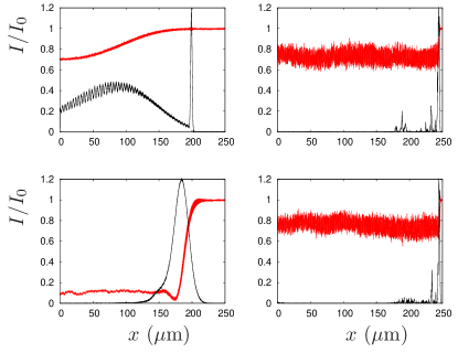
The intensity of the pump affects the amplification process in many ways. The use of lower pump intensities ( W/cm2) will of course reduce the growth rate of parasitic instabilities. However, a longer pump and thicker plasma slab will be needed to amplify the probe to a similar final intensity, which allows parasitic instabilities more time to grow. On balance, we found that it is often better to increase the pump intensity and reduce the thickness of the plasma slab, as this leads to a smaller total influence of parasitic instabilities. In addition, lower pump intensities favour the amplification of longer probes, while increasing the pump intensity will lead to a shorter probe after amplification. Even if a short initial probe is used, the narrowband linear amplification that occurs at low intensities will reduce the probe’s bandwidth and increase its length, as predicted in Ref. shvets99 . For higher pump intensities ( W/cm2), the amplification process will be much faster, so the pump depletion length will be shorter and the amplification of shorter probes will be favoured. However, when the pump is too intense ( W/cm2) the amplification of the probe may be curbed by wave breaking of the RBS Langmuir wave. This will happen when the combined pump and probe intensities become too large, and will stop the energy flow from pump to probe long before the pump is fully depleted, thus sharply reducing the efficiency of the process. The effect of the pump intensity on the length of the amplified probe is illustrated by the simulation results depicted in Figure 3.
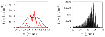
Since the maximum amplification/compression factor is limited to about 200 by saturation, while the pump intensity cannot be too high because of pump instabilities and Langmuir wave breaking, the most reliable way to increase the total energy of the amplified probe is to attempt to amplify wider pulses. This requires a thorough understanding of all transverse effects that occur during Raman amplification. Until now, transverse effects in Raman amplification have not received much attention in theoretical studies. Some 3-D hydrodynamic simulations have been conducted balakin03 ; balakin05 , but these do not include the full gamut of transverse laser-plasma instabilities. The only available 2-D PIC simulations mardahl restrict themselves to narrow pulses (4-6 m) and short propagation distances ( mm) in a preformed plasma channel. However, much wider pulses are needed (1-10 mm and beyond) to push Raman amplification to truly high intensities fisch03 ; malkin05 ; malkin07 . Pulses of such width may be affected by various transverse phenomena, such as self-focusing sprangle87 , filamentation kaw73 and gain narrowing (when the centre of the probe is amplified more efficiently than the wings because of its intrinsically higher intensity, and an effective narrowing of the probe occurs). To study these effects we have carried out the first 2-D full-PIC simulations ever that use wide pulses (widths of 300 and 600 m) in a homogeneous plasma. The results of these simulations are displayed in Figure 4, which shows the amplified probe intensity profiles resulting from these simulations. Here, the pump intensity was W/cm2, the probe intensity was W/cm2, the probe duration was 50 fs and or 20 was used, with a flat transverse density profile. For both densities, the probe was amplified to several times W/cm2, but it also suffered from transverse filamentation, in particular for . During early stages of the amplification, a transverse envelope modulation with a period of emerges, while merging of narrow filaments into wider ones occurs during later stages. For , this effect is so strong that complete filamentation occurs after only 2.4 mm propagation. For the effect is much less prominent, which allowed the probe to reach W/cm2 in 25-30 fs after 4 mm of propagation before its envelope started to break up. For a 600 m wide probe, this implies a peak power of around 2 PetaWatt, with an estimated efficiency of 30-40 %. Note that the probe growth would have saturated for longer propagation distances anyway, so transverse effects need not limit the maximum amplification even further for the right set of parameters. This particular scenario has several characteristics that make it work. The plasma density is fairly low, so the probe fits into a single plasma period, inhibiting RFS and modulational instabilities. In addition, pump and probe instabilities do not grow out of control for several mm of propagation. Pump and probe intensities are fairly high, so the probe is rapidly and efficiently amplified over a short distance, but they do not yet trigger severe growth of parasitic instabilities or Langmuir wave breaking at this density. Simulations of a more intense pump ( W/cm2) revealed filamentation of the pump front after 2 mm, before meeting the probe, emphasizing the importance of using the right combination of pump intensity, plasma density and propagation distance. Most importantly, there is no fundamental disadvantage to extending this scenario to pulses much wider than 600 m.
Although the results at indicate that this density is too high for the amplification of wide pulses, they still provide important information on the transverse behaviour of the amplified probe. Merging of filaments and self-focusing of individual filaments can be observed, but there is no evidence of whole-beam self-focusing (outlying filaments are not pushed towards the pulse centre during the first few mm of propagation). This is in line with the observation that whole-beam relativistic self-focusing is inhibited by the transverse density modulation that accompanies the filamentation instability. There is no evidence of gain narrowing: the relative amplification of individual filaments does not appear to depend on their transverse position. Based on these results, we predict that the narrowing of the probe pulse observed by Ren et al. ren07 stems from focusing of the probe in the preformed plasma channel rather than gain narrowing or relativistic self-focusing, as the amplified probe is sufficiently narrow with respect to to behave as a single filament.
Pulse filamentation puts restrictions on the range of useful pump intensities: too low, and the probe will have to propagate in plasma for too long, causing it to filament; too high, and the pump will filament itself. Probe filamentation will also limit the extent to which the probe can be focused, so the probe amplification has to be stopped before it grows too large. Nevertheless, good amplification can still be obtained with a proper choice of parameters. For example, the results displayed in Figure 4 show that a 10 TW, 20 ps pump of up to 1 mm diameter, containing 200 J, can be compressed to less than 100 fs and up to 2 PW using a homogeneous plasma column of several mm long and wide, which appears experimentally feasible. The maximum amplification of the probe is limited by nonlinear saturation and again by filamentation; realistically, the probe can be amplified to about 200 times the intensity of the pump before either effect sets in. Therefore, the only way to increase the energy content of the amplified probe is to increase the transverse dimensions of pulses and plasma while keeping the plasma slab thin. Although it is not possible to do this for both transverse directions, it may be achieved for one direction using an elongated supersonic gas flow and a line focus for the pulses.
In this paper, we have shown for the first time, through numerical simulations, that there are limits to Raman amplification set by various instabilities of both pump and probe pulses. This reduces the useful ranges of the experimental parameters. If the plasma density is too low (), the energy transfer is inefficient; too high (), and filamentation will destroy the pulse profiles. If the pump intensity is too low ( W/cm2), the probe will take too long to amplify, allowing probe filamentation and RFS to grow out of control; too high ( W/cm2), and the pump will be wasted by parasitic RBS and filamentation even before it meets the probe. The length of the plasma column is limited to a few mm by probe saturation and filamentation and various pump instabilities. For an ideal choice of parameters, probe saturation and filamentation would occur after roughly the same propagation distance, while both the plasma density and pump intensity would be high enough to allow for efficient amplification, low enough to inhibit pump instabilities occurring over the length of the plasma column. We have found that probe amplification up to the PetaWatt level is possible in 4 mm for , a W/cm2 pump, and 600 m wide pulses. Even so, low-level filamentation will limit the focusability and thus the peak intensity of the probe. Since the proposed scenarios for Raman amplification beyond W/cm2 rely on either extreme focusability fisch03 ; malkin07 , very long propagation lengths and intense pumps malkin05 , or a very high plasma density () malkin07 , they are not feasible in light of our new simulation results, and the Schwinger limit is out of reach for the foreseeable future. However, if the limits to Raman amplification set by the various instabilities are properly observed, there is a narrow but definite parameter window in which good amplification can be obtained.
This work was supported by the STFC Accelerator Science and Technology Centre and the STFC Centre for Fundamental physics, and by FCT (Portugal) through grant PTDC/FIS/66823/2006. We would like to thank W. Mori and D. Jaroszynski for useful discussions, the Plasma Theory and Simulation Group of UC Berkeley for the use of XOOPIC, and the OSIRIS consortium for the use of OSIRIS. Some of the simulations were performed using the IST Cluster, Lisbon.
References
- (1) G. Shvets et al., Phys. Rev. Lett. 81, 4879 (1998).
- (2) V.M. Malkin et al., Phys. Rev. Lett. 82, 4448 (1999).
- (3) V.M. Malkin et al., Phys. Rev. Lett. 84, 1208 (2000).
- (4) V.M. Malkin et al., Phys. Plasmas 7, 2232 (2000).
- (5) V.M. Malkin et al., Phys. Rev. Lett. 85, 4068 (2000).
- (6) Yu.A. Tsidulko et al., Phys. Rev. Lett. 88, 235004 (2002).
- (7) A.A. Balakin et al., Phys. Plasmas 10, 4856 (2003).
- (8) B. Ersfeld and D.A. Jaroszynski, Phys. Rev. Lett. 95, 165002 (2005).
- (9) H.J. Lee et al., IEEE Trans. Plas. Sci. 30, 40 (2002).
- (10) P. Mardahl et al., Phys. Lett. A 296, 109 (2002).
- (11) M.S. Hur et al., Phys. Plasmas 11, 5204 (2004).
- (12) D.S. Clark and N.J. Fisch, Las. Part. Beams 23, 101 (2005).
- (13) A.A. Balakin et al., IEEE Trans. Plas. Sci. 33, 488 (2005).
- (14) M.S. Hur et al., Phys. Rev. Lett. 95, 115003 (2005).
- (15) A.A. Andreev et al., Phys. Plasmas 13, 053110 (2006).
- (16) Y. Ping et al., Phys. Rev. Lett. 92, 175007 (2004).
- (17) M. Dreher et al., Phys. Rev. Lett. 93, 095001 (2004).
- (18) W. Cheng et al., Phys. Rev. Lett. 94 045003 (2005).
- (19) R.K. Kirkwood et al., Phys. Plasmas 14, 113109 (2007).
- (20) J. Ren et al., Nature Physics 3, 732 (2007).
- (21) N.J. Fisch and V.M. Malkin, Phys. Plasmas 10, 2056 (2003).
- (22) V.M. Malkin and N.J. Fisch, Phys. Plasmas 12, 044507 (2005).
- (23) V.M. Malkin, N.J. Fisch and J.S. Wurtele, Phys. Rev. E 75, 026404 (2007).
- (24) I.N. Ross et al., Opt. Comm. 144, 125 (1997).
- (25) O. Checkhlov et al., Proc. SPIE 6735, 67350J (2007).
- (26) J.P. Verboncoeur, A.B. Langdon and N.T. Gladd, Comp. Phys. Comm. 87, 199 (1995).
- (27) R.A. Fonseca, L.O. Silva, R.G. Hemker, et al., Lect. Not. Comp. Sci. 2331, 342 (2002).
- (28) P. Sprangle, C.-M. Tang, and E. Esarey, IEEE Trans. Plas. Sci. 15, 145 (1987).
- (29) P. Kaw, G. Schmidt, and T. Wilcox, Phys. Fluids 16, 1522 (1973).