Ultracold-neutron infrastructure for the gravitational spectrometer GRANIT
Abstract
The gravitational spectrometer GRANIT will be set up at the Institut Laue Langevin. It will profit from the high ultracold neutron density produced by a dedicated source. A monochromator made of crystals from graphite intercalated with potassium will provide a neutron beam with Å incident on the source. The source employs superthermal conversion of cold neutrons in superfluid helium, in a vessel made from BeO ceramics with Be windows. A special extraction technique has been tested which feeds the spectrometer only with neutrons with a vertical velocity component cm/s, thus keeping the density in the source high. This new source is expected to provide a density of up to for the spectrometer.
keywords:
Ultracold neutron production, Ultracold neutron, potassium graphite intercalated compound, , , , , , , , ,
Introduction
The solutions for Schrödinger’s equation for a neutron bouncing on a reflecting horizontal surface in the Earth’s gravitational field are given by Airy functions [1, 2]. This textbook example of bound energy states in a linear potential has been demonstrated experimentally at the high flux reactor of the Institut Laue Langevin [3, 4]. A new gravitational spectrometer, GRANIT [5, 6], is being built to investigate these quantum states further, and to induce resonant transitions between gravitationally bound quantum states. Proposed applications are a refined measurement of the electrical charge of the neutron, the search for the axion [7, 8] and other additional forces beyond the standard model. Experiments at ILL’s present facility PF2 for ultracold neutrons (UCN) are limited by counting statistics and systematic effects [9]. In this paper we describe design and status of a dedicated UCN source and its coupling to the gravitational spectrometer, updating a previous status report [10].
General aspects of Helium-4 based superthermal converters
The UCN source employs down-conversion of monochromatic cold neutrons with wavelength around 8.9 Å in superfluid helium, via single-phonon excitation [11]. The saturated UCN density in the converter,
| (1) |
is determined by production rate density and neutron storage time constant . The rate
| (2) |
includes contributions from all existing loss channels (neutron beta decay, losses due to wall collisions, up-scattering due to phonons, nuclear absorption by 3He - impurities in the helium, extraction of UCN111Helium-4 based UCN sources are usually used in accumulation mode, without extraction during accumulation. In this paper, we are discussing a source providing a quasi-continuous flux of UCN.).
As the absorption cross section of 4He is zero there is no absorption inside a pure converter. For K the up-scattering cross section becomes negligible, and therefore is determined only by neutron beta decay, losses due to wall collisions, and extraction of UCN.
The UCN production rate density is defined as the conversion rate of neutrons to energies below the Fermi potential of the walls of the converter volume. For beryllium with neV the production rate density due to the single-phonon process, calculated from neutron scattering data, is , with the differential flux at Å given in Å -1 [13].
Source concept
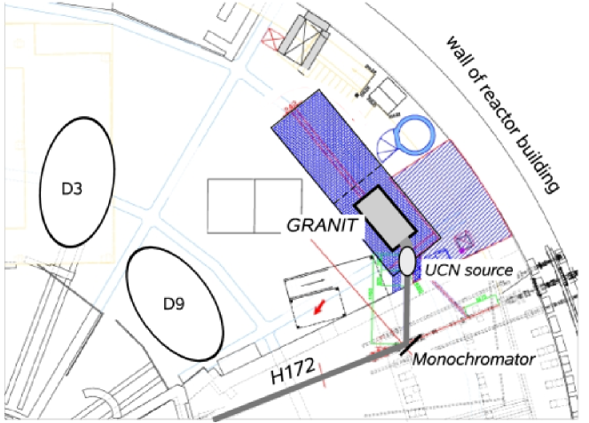
The UCN source employs cold neutrons from the neutron beam H172 on level C of the high flux reactor at the ILL (see fig. 1). A crystal monochromator, positioned 12 m downstream from the liquid-deuterium cold source situated in-pile reflects neutrons with 8.9 Å out of the direct beam. It feeds a secondary, 4.5 m long neutron guide equipped with supermirror coatings. The superfluid-helium UCN converter with its special UCN extraction system is installed at the end of this guide. The individual components of the source implementation are described in the following subsections.
Neutron monochromator
Single-phonon downscattering of cold neutrons in superfluid helium as UCN production mechanism requires only a narrow range of wavelengths around 8.9 Å . Using a monochromator and a secondary guide strongly reduces the background with respect to a converter placed in the direct, white beam. The price to be paid is a reduction in intensity due to imperfection of monochromator and secondary guide, and due to omission of multi-phonon processes [12, 13].
Crystal monochromators reflect neutrons of the desired wavelengths away from the primary beam under the -spacing dependent Bragg angle:
| (3) |
The -spacing of a monochromator for Å has to be Å. In a perfect single crystal the line width for Bragg reflected neutrons is extremely small, [14] leading to a very narrow acceptance angle of incident neutrons:
| (4) |
The incident beam has a divergence of typically at Å due to the supermirrors used in the guide. Therefore a “mosaic crystal” [14] is used. Such a crystal can be regarded as a collection of microscopically small perfect crystals with differing angles with respect to the overall crystal orientation. Although the angular distribution is in general arbitrary, it resembles a cylindrically symmetric Gaussian distribution with a width , called the mosaicity. To obtain a high acceptance the mosaicity should be in the range of the divergence of the incident beam [15]. A high reflectivity of the crystal for Å neutrons is required, too. Mica and graphite intercalated compounds (GiC) with alkali metals both match the requirements for the lattice spacing. However, due to the too small mosaicity of mica we are using a potassium intercalated graphite monochromator of the type already employed at the ILL and NIST [16, 17, 18]. For highly oriented pyrolytic graphite the spacing is Å with a typical mosaicity of . The -spacing is increased by placing guest species in between graphite layers (see fig. 2). This process is called intercalation.
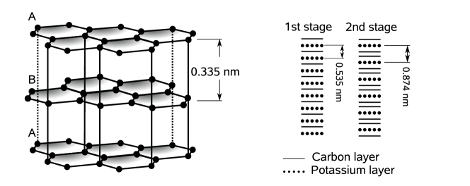
Alkali intercalated graphite compounds are conveniently produced using the “two-bulb” technique, where the graphite is maintained at a temperature which is higher than of the alkali metal [19]. The stage which is formed depends on the temperature difference and the quantity of potassium available. For stage-1, stage-2 we are employing 5 g, 1 g ampoules of potassium at and , , respectively.
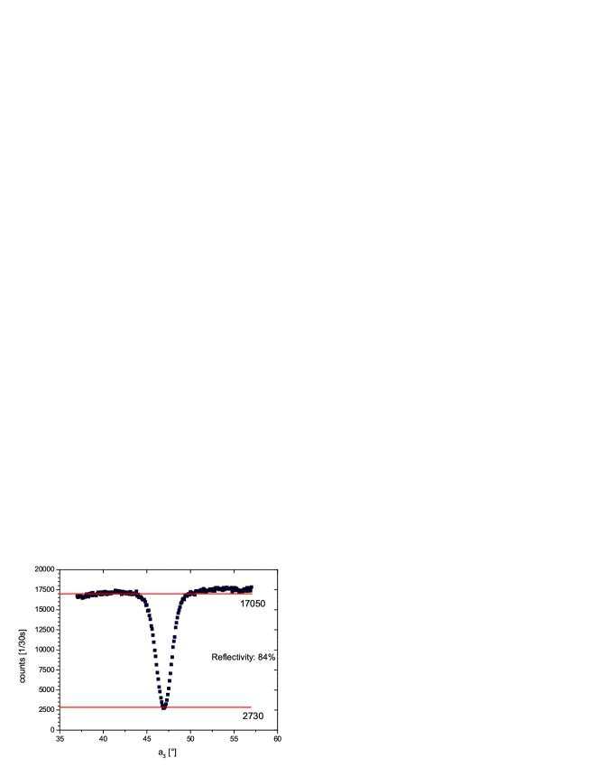
The monochromator consists of 18 stage-2 potassium intercalated graphite crystals () providing a lattice spacing of Å giving a take-off angle of . The typical mosaic spread of the produced crystals is which matches the incident divergence of beam H172. Furthermore the thermal-neutron absorption cross sections of carbon (0.0035 barn) and potassium (2.1 barn) are small. The crystals are mounted pair-wise onto graphite bars which then are screwed into an indium sealed aluminum box. First crystals with a reflectivity of % (see fig. 3) have been produced.
A second monochromator with a take-off angle of made of a set of stage-1 crystals (C8K, Å) will be placed close to the first one on a rotary table. The two monochromators can be interchanged making two separate Å beam ports available at H172 (see fig. 1). The second beam will feed a position for further tests and developments on liquid helium based UCN sources, and later for the cryo-EDM experiment [20].
Secondary neutron guide, UCN converter and cryostat
General requirements for producing a high density of UCN in a converter vessel filled with superfluid-helium are an intense incident beam, and for the walls a high Fermi potential with a small loss-per-bounce coefficient . A converter vessel with polished, flat wall surfaces may keep together a divergent incident beam. On the other hand, for short sources, rough surfaces seem to support faster UCN extraction compared to polished ones [21]. A converging secondary neutron guide may increase the flux density of 8.9 Å neutrons at the entrance to the converter. However, the increased divergence might result in a strong decrease of flux density along the converter for rough and/or low-Fermi-potential walls.
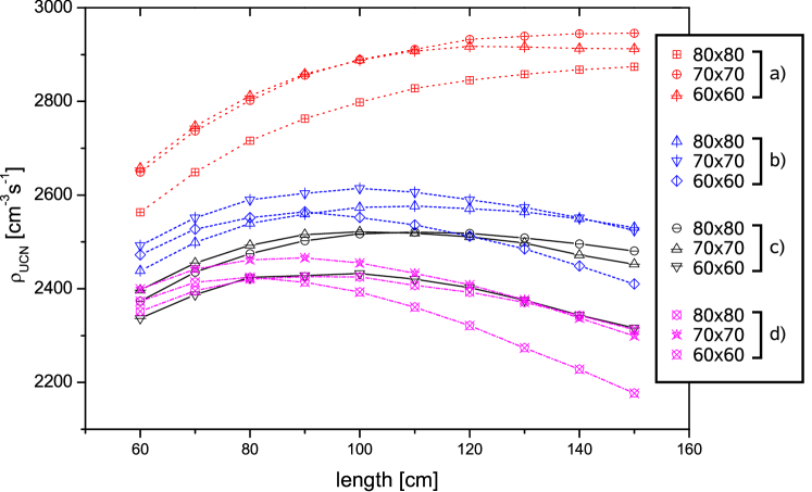
Monte Carlo simulations were performed to investigate UCN production for various guide geometries and wall properties (see fig. 4). Taking into account also other constraints we decided to employ as converter vessel an assembly of 5 rectangular BeO tubes, closed by Be foils, thus taking advantage of the high Fermi potential of these materials (261 neV and 252 neV, respectively). The flux incident on the monochromator, , was calculated from known cold-source data and a transmission simulation for the existing guide. The peak reflectivity of % of the monochromator corresponds to an integral reflectivity of % for the divergent 8.9 Å beam. The neutron guide between monochromator and source converges over a length of m from a to the cross section indicated in fig. 4.
The simulations show that, for a conversion volume with the properties defined above, with a cross section of 7070 mm2, a length of 1 m, and taking , we expect an UCN density of .
UCN are extracted from the converter through specular tubes into an intermediate volume (see fig. 5). To suppress heat load from thermal radiation along the tube we use an UCN shutter thermally anchored to the K screen of the cryostat. The intermediate volume, at room temperature, is equipped with a second UCN shutter at the entrance. Both shutters are operated in sequential mode to establish and maintain a high UCN density inside the intermediate volume. The UCN yield of our window-free, vertical UCN extraction is much improved with respect to an older scheme with horizontal UCN extraction through foils [22]. A bent in the extraction guide reduces background from directly scattered cold neutrons.
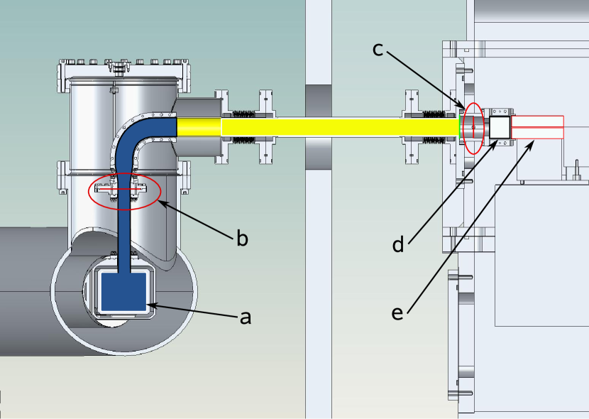
For filling and cooling the converter volume with liquid helium we employ a cryostat previously developed at Munich. For some general description of the apparatus and first experiments on UCN production see [23]. The apparatus includes a Gifford McMahon cryocooler with 1.5 W at 4.2 K, which serves for liquefaction of helium from gas bottles [24] and for cooling heat screens to 50 K and 4 K. A 4He evaporation stage cools liquid helium to the superfluid phase, allowing us to use a superleak to remove 3He. The cooling of the converter volume is achieved with a 3He closed cycle evaporation stage. Using a roots blower pump with 500 nominal pumping speed backed by a 40 multiroots pump we were so far able to cool the filled converter to 0.7 K. An ongoing upgrade of the apparatus shall bring the temperature down to 0.5 K.
UCN selection with semidiffuse channel
The first experiments with the gravitational spectrometer GRANIT require a quasi-continuous flux of UCN within a narrow phase space element, for which a special UCN extraction system has been developed. UCN from the converter are guided to the intermediate volume by a highly polished nickel or diamond-like carbon (DLC) coated guide (fig. 5). The intermediate volume is made of rough DLC-coated aluminum plates, providing mixing in the phase space of stored neutrons. The optimum size of the volume was determined by simulations with Geant4UCN [25] to be 4040 , the width 300 mm is given by the dimensions of the spectrometer.
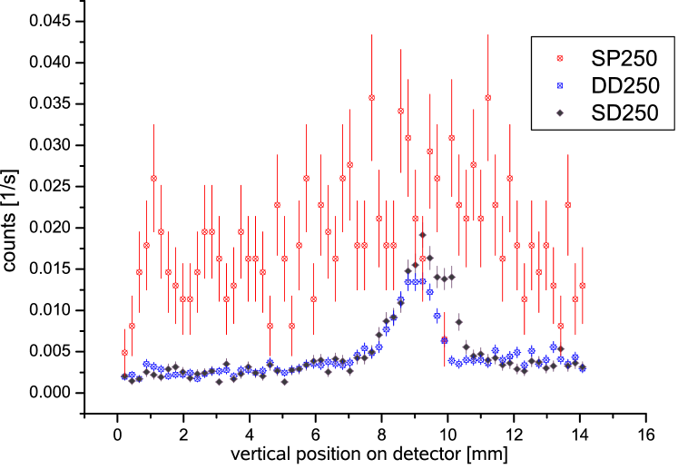
UCN are extracted from the intermediate volume via a narrow horizontal semidiffuse extraction channel described in [26, 27]. Measurements have shown that such a channel increases the storage time inside the intermediate volume since more than 80% of the neutrons incident on the channel are reflected back. These neutrons are lost in conventional collimation systems whereas they increase the UCN density here and in turn the flux of extracted neutrons. The phase space selectivity of the extraction channel is demonstrated in fig. 6. For GRANIT it will be made of DLC coated quartz plates, with the lower surfaces polished and the upper ones rough. The channel dimensions are mm, mm, thus selecting neutrons with a vertical energy component peV with respect to the channel bottom. We expect a reflectivity (fraction of neutrons that return from the channel to the storage volume) of % for all other neutrons.
Conclusion
Prototypes of monochromator crystals, the converter, and the semidiffuse channel have all been tested separately. The design of the full set-up is finalized, and the components are being produced. Calculations with an incident differential flux on the monochromator give an UCN density of in the converter and up to in the intermediate volume. This yields an available phase-space density of for the critical velocity of m/s of the used materials. Compared to the phase-space density of the UCN turbine at the ILL this is more than a factor ten of improvement. This calculation assumes perfect conditions and in all parts optimal transmissions. The integration of source, intermediate volume and extraction channel is a challenging task, and further optimization may be needed to approach the calculated densities.
Acknowledgement
We are grateful to our colleagues from the GRANIT collaboration, the monochromator collaboration with NIST, and the DPT of the ILL for fruitful discussions and support. This work is supported by the German BMBF (contract number 06MT250) and by the French Agence de la Recherche (ANR).
References
- [1] S. Flügge, Practical Quantum Mechanics, vol. 1, Springer-Verlag, Berlin (1971).
- [2] V.I. Luschikov and A.I. Frank, JETP Lett. 28 (1978) 559.
- [3] V.V. Nesvizhevsky et al., Nature 415 (2002) 297.
- [4] V.V. Nesvizhevsky et al., Phys. Rev. D 67 (2003) 102002.
- [5] V.V. Nesvizhevsky and K.V. Protasov, Quantum states of neutrons in the Earth’s gravitational field: state of the art, applications and perspectives, in: D.C. Moore (ed.), Trends in quantum gravity research, Nova Science Publishers, New York (2006), pp. 65-107.
- [6] M. Kreuz et al., Nucl. Instr. and Meth. A (these proceedings).
- [7] S. Baeßler et al., Phys. Rev. D 75 (2007) 075006.
- [8] S. Baeßler et al., Nucl. Instr. and Meth. A (these proceedings).
- [9] G. Pignol et al., arXiv:0708.2541v1.
- [10] P. Schmidt-Wellenburg et al., arXiv:0708.1373v2.
- [11] R. Golub and J.M. Pendlebury, Phys. Lett. A 53 (1975) 133.
- [12] C.A. Baker et al., Phys. Lett. A 308 (2003) 67.
- [13] P. Schmidt-Wellenburg et al., Nucl. Instr. and Meth. A (these proceedings).
- [14] M.L. Goldberger and F. Seitz, Phys. Rev. 71 (1947) 294.
- [15] K.-D. Liss and A. Magerl, Nucl. Instr. and Meth. A 338 (1994) 90.
- [16] A. Boeuf et al., Synthetic Metals 8 (1983) 307.
- [17] http://www.ill.eu/db21/.
- [18] C.E.H. Mattoni et al., Physica B 344 (2004) 343.
- [19] A. Hérold, Bull. Soc. Chim. Fr., 5e série, (1955) 999.
- [20] M. v.d. Grinten, Nucl. Instr. and Meth. A (these proceedings).
- [21] O. Zimmer et al., arXiv:0801.4839.
- [22] A.I. Kilvington et al., Phys. Lett. A 125 (1987) 416.
- [23] O. Zimmer et al., Phys. Rev. Lett. 99 (2007) 104801.
- [24] P. Schmidt-Wellenburg and O. Zimmer, Cryogenics 46 (2006) 799.
- [25] F. Atchison et al., Nucl. Instr. and Meth. A 552 (2005) 513.
- [26] P. Schmidt-Wellenburg et al., Nucl. Instr. and Meth. A 577 (2007) 623.
- [27] J. Barnard and V. Nesvizhevsky, Nucl. Instr. and Meth. A 591 (2008) 431.
- [28] J. Jakubek et al., Nucl. Instr. and Meth. A, in press, doi:10.1016/j.nima.2008.12.078.