Exchange coupling between two ferromagnetic electrodes separated by a graphene nanoribbon
Abstract
In this study, based on the self-energy method and the total energy calculation, the indirect exchange coupling between two semi-infinite ferromagnetic strips (FM electrodes) separated by metallic graphene nanoribbons (GNRs) is investigated. In order to form a FM/GNR/FM junction, a graphitic region of finite length is coupled to the FM electrodes along graphitic zigzag or armchair interfaces of width . The numerical results show that, the exchange coupling strength which can be obtained from the difference between the total energies of electrons in the ferromagnetic and antiferromagnetic couplings, has an oscillatory behavior, and depends on the Fermi energy and the length of the central region.
I Introduction
Magnetic exchange interaction between ferromagnetic (FM) layers separated by a nonmagnetic metal spacer has been investigated to a large extent because of both possible applications exploiting the giant magnetoresistance effect and the expectation of the way to the production of nonvolatile computer memories, extremely efficient magnetic sensors, and magnetic materials with enhanced information storage capacity Hathaway ; Heinrich . Among low-dimensional structures, graphene nanoribbons (GNRs) and carbon nanotubes (CNTs) are potentially useful for magneto-transport applications. For that purpose, GNRs and CNTs must interact with magnetic foreign objects such as substrates, impurities, adsorbed atoms, and nanoparticles Kirwan ; Shenoy . When the separation between the magnetic objects increases, the direct exchange interaction between magnetic moments decays abruptly since this interaction requires a finite overlap between the wave functions that surround the respective magnetic objects. Therefore, when the moments are not too close together there is no direct overlap between their wave functions. In such a case, the only way a magnetic coupling can arise is if it is mediated by the conduction electrons of the metallic host. Understanding the physics of this so-called indirect exchange coupling between localized magnetic moments mediated by the conduction electrons of metallic hosts might provide clues to making magnetic carbon-based structures which could be applicable in spintronic devices Costa .
In the field of exchange coupling of magnetic trilayers or multilayers, many methods and models have been employed, such as the first-principles method Herman1 , the tight-binding total energy calculation Hasegawa1 , the Ruderman-Kittel-Kasuya-Yosida (RKKY) theory Bruno , the one-band tight-binding hole-confinement model Li , the free-electron model Barnas , etc. In this article, based on the single-band tight-binding approximation and the self-energy method, we investigate the indirect exchange coupling between two semi-infinite FM electrodes separated by metallic armchair GNRs (AGNRs) and zigzag GNRs (ZGNRs).
II Model and formulation
We consider a magnetic nanostructures consisting of two semi-infinite FM nanostripes (electrodes) separated by a graphitic region of length (in the direction) and width (in the direction). Since we study the exchange coupling between two FM electrodes, the electronic structure of the central part of the junction (i.e. GNR) should be resolved in detail. It is therefore reasonable to decompose the total Hamiltonian of the system as . For simplicity, we treat a square lattice structure for the FM electrodes. The Hamiltonian for such electrodes is written within the tight-binding approximation as
| (1) |
where () creates (destroys) an electron with spin at site in electrode (=L, R), and is the hopping matrix element between nearest-neighboring sites and . Here, is the spin independent on-site energy and will be set to zero, is the internal exchange energy with denoting the molecular field at site , and being the conventional Pauli spin operator. On the other hand, the Hamiltonian of GNR in the absence of FM electrodes is expressed as
| (2) |
where () creates (destroys) an electron with spin at site of GNR. Finally, describes the coupling between the electrodes and the GNR and takes the form . The hopping elements between the orbitals of the GNR, and also between the lead orbitals and the orbitals of the GNR are taken to be ; that is, the hopping parameters are same in the three regions.
In this study we assume that the spin direction of the electron is conserved in the propagating process through the GNR. Therefore, there is no spin-flip process and the spin-dependent transport can be decoupled into two spin channels: one for spin-up and the other for spin-down. On the other hand, it is well known that the effect of semi-infinite electrode on the GNR can be described by a (spin-dependent) self-energy matrix Datta . Therefore, it is reasonable to write , where . Now the spin-dependent Green’s function of the GNR coupled to the two FM electrodes is given as
| (3) |
where the self-energy matrices contain the information of the electronic structure of the FM electrodes and their coupling to the GNR. These matrices can be expressed as
| (4) |
where is the hopping matrix that couples the GNR to the leads and is determined by the geometry of the GNR-lead bond. are the surface Green’s functions of the uncoupled leads i.e., the left and right semi-infinite magnetic electrodes, and their matrix elements are given by
| (5) |
Here, , , and with is the number of lattice sites in the direction. In order to calculate the total energy, we need the total density of states per site for the electron of spin (= or ) which is given as where is the total number of carbon atoms in the GNR. Thus, at K, the total energy of the electrons that occupy the levels up to the Fermi energy in FM (antiferromagnetic (AF)) configuration is given by
| (6) |
The indirect exchange coupling , is defined as the total energy difference between the FM and AF configurations of the system:
| (7) |
Based on the above formalism, we calculate for two different junctions.
![[Uncaptioned image]](/html/0811.0934/assets/x3.png)
![[Uncaptioned image]](/html/0811.0934/assets/x4.png)
III Numerical results and discussions
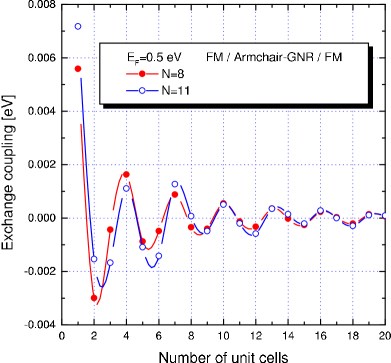
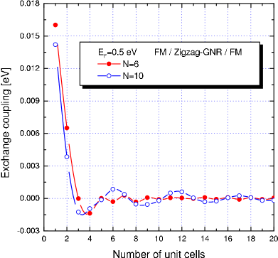
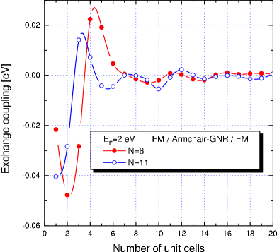
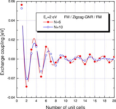
We have done the numerical calculations for the case that the direction of magnetization in the left FM electrode is fixed in the +, while the magnetization in the right electrode is free to be flipped into either the + or - direction. We set =1.5 eV and =1 eV in the calculations. Our results clearly show that oscillates with increasing the length of graphitic region in both FM/AGNR/FM (Figs.1 and 3) and FM/ZGNR/FM (Figs.2 and 4) junctions. It can be seen from the figures that as the length of GNR increases, the oscillation amplitudes of decrease. Also, the oscillatory phase changes by varying the Fermi energy. We can ascribe the indirect coupling to the interferences of electron waves in the metallic GNRs because of spin-dependent reflections at the FM/GNR interfaces. Electron states in the GNR can be propagative Bloch waves, but also evanescent waves due to the finite length of the spacer. Propagative states give rise to oscillatory contributions to the coupling, while evanescent states yield damping terms.
Therefore, both kinds of states contribute to . Their importance depends essentially on the nature of the states at the Fermi level. It is clear from the figures that, in most cases, when the separation between two electrodes exceeds 15 unit cells, the coupling between two magnetic electrodes becomes very small. These results may be useful for understanding the strength of exchange coupling between two magnetic impurities or adsorbed atoms on GNRs and CNTs.
References
References
- (1) Hathaway K B 1994 in Ultrthin Magnetic Structure ed Heinrich B and Bland J A C (Berlin: Springer) Vol. II
- (2) Heinrich B and Cochran J F 1993 Adv. Phys. 42 523
- (3) Kirwan D F, Rocha C G, Costa A T, and Ferreira M S 2008 Phys. Rev. B 77 085432
- (4) Shenoy V B 2005 Phys. Rev. B 71 125431
- (5) Costa A T, Muniz R B, and Ferreira M S 2008 Cond-mat 0803-0028
- (6) Herman F, Sticht J, and van Schilfgaarde M 1991 J. Appl. Phys. 69 4783
- (7) Hasegawa H and Herman F 1988 Phys. Rev. B 38 4863
- (8) Bruno P and Chappert C 1992 Phys. Rev. B 46 261
- (9) Li Lie-Ming, Li Bo-Zang, and Pu Fu-Cho 1994 J. Phys.: Condens. Matter B 6 1941
- (10) Barnaś 1992 J. Magn. Magn. Mater. 111 L215
- (11) Datta S 2005 Quantum Transport: Atom to Transistor (New York, Cambridge)