Magnetic-force-microscope study of interlayer “kinks” in individual vortices in underdoped cuprate YBa2Cu3O6+x superconductor
Abstract
We use magnetic force microscopy to both image and manipulate individual vortex lines threading single crystalline YBa2Cu3O6.4, a layered superconductor. We find that when we pull the top of a pinned vortex, it may not tilt smoothly. Sometimes, we observe a vortex to break into discrete segments that can be described as short stacks of pancake vortices, similar to the “kinked” structure proposed by Benkraouda and Clem. Quantitative analysis gives an estimate of the pinning force and the coupling between the stacks. Our measurements highlight the discrete nature of stacks of pancake vortices in layered superconductors.
pacs:
74.72.-h,68.37.Rt, 74.25.QtMagnetic field penetrates superconductors in the form of vortices, each carrying one magnetic flux quantum, . In the highly anisotropic cuprates, where the c-axis penetration depth () is much larger than the in-plane penetration depth (), the three-dimensional vortex can be treated as a stack of two-dimensional, magnetically coupled, “pancake” vortices Clem (1991); Artemenko and Kruglov (1990), with weak interlayer Josephson coupling Clem (2004); Bulaevskii et al. (1992). Rich physics arises from the competition between thermal energy, vortex-vortex interactions, pinning and the interlayer coupling. While numerous studies have been done on vortex-matter thermodynamics, mostly by measuring macroscopic properties Blatter et al. (1994); Beidenkopf et al. (2007); Figueras et al. (2006), work on individual vortices is scarce. Magnetic force microscopy (MFM) allows us to manipulate individual vorticesMoser et al. (1998) with a high level of control Straver et al. (2008); Auslaender et al. (2008). Here we use MFM to directly probe the pinning energy and the interlayer coupling energy, which determine the shape of a vortex and the nature of its motion.
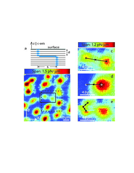
In a layered superconductor a vortex subject to shear can theoretically break into separate straight stacks of pancakes, to create a kinked structure , instead of tilting Benkraouda and Clem (1996) [Fig. 1(a)]. Previous researchers have identified such kinked vortices by direct imaging Guikema et al. (2008); Beleggia et al. (2004); Grigorenko et al. (2002), proposed a model for kinked stacks in the presence of pinning Benkraouda and Clem (1996); Guikema et al. (2008), and discussed the interaction between pancake vortices and Josephson vortices Grigorenko et al. (2001); Vlasko-Vlasov et al. (2002). Here we use MFM to directly test the picture of kinked vortices interacting with pinning and to measure the coupling between the stacks composing a single vortex in an underdoped YBa2Cu3O6+x (YBCO) single crystal. We sometimes observe pairs of well separated magnetic features on the sample surface carrying sub- flux. Using the magnetic tip of the MFM for manipulation, we combine pairs of features to create regular, , vortices, verifying the kinked stack picture. As further corroboration, we split regular -vortices by pulling them apart to create kinks. We measure the required force, obtaining an estimate for the attractive interaction between stacks. The result agrees well with a model of magnetic coupling augmented by the line-tension of the Josephson string connecting the stacks.
The YBCO single crystal was grown by the self-flux method in BaZrO3 crucibles Liang et al. (1998), mechanically detwinned and annealed. The platelet-shaped crystal (face parallel to the ab-plane, dimensions ) is 100 m thick. The anisotropy of YBCO increases as the superconducting transition temperature drops with reduced doping. For our sample, K (transition width K), implying and therefore m and at zero temperature Hosseini et al. (2004); Broun et al. (2007); Liang et al. (2005), comparable to that of the highly anisotropic superconductor Bi2Sr2CaCu2O8 ()Blatter et al. (1994).
Our measurements are performed in a variable-temperature MFM in frequency modulation mode Albrecht et al. (1991). A magnetic tip at the end of a cantilever Can is scanned at a constant height above the sample surface which is experimentally determined by obtaining a parabolic fit to dozens of touching down positions. The force between the tip and the sample induces a shift of the resonant frequency of the cantilever, , which we measure. Subtracting a -dependent offset, we obtain the contribution of the tip-vortex interaction, , which gives information on the tip-vortex force, , where N/m is the cantilever spring constant Spr and kHz. In our scans, the tip moves back and forth along the x-axis, then, after completing one period of motion (duration of a few seconds), it is incremented along either or . The choice differs from scan to scan.
The force exerted by the tip on the sample is generally regarded as a drawback of MFM. Here, we magnetize the tip by placing near it a permanent magnet with the polarity chosen to give attractive tip-vortex force. We deliberately use the lateral components of this force, , to overcome the pinning force, , in order to manipulate individual vortices. We tune by varying the scan height . We first image at a height where the tip force is insufficient to perturb the vortices, which are held static by , i.e. . For manipulation, we reduce to increase [in the model described below, for ]. When we can manipulate a vortex. Temperature, which reduces , gives extra control Auslaender et al. (2008).
For low vortex density, we cooled the sample in a magnetic field of T along the crystal’s c-axis. Fig. 1(b) shows an image acquired at K, in which vortices appear as peaks. Most vortices give the same peak height, as expected, since they each should carry a flux of exactly . However, some peaks have weaker amplitude and always appear in pairs [e.g. in the solid framed region in Fig. 1(b)], indicating the flux associated with each member is less than . Previous work Guikema et al. (2008) suggests that these peaks originate from kinked stacks of pancake vortices forming one -vortex. To test this model, we annihilated kinks and then recreated them [Figs. 1(c)-(e)]. For the manipulation we heated the sample to K, to reduce . Then, after locating two distinct partial stacks [Fig. 1(c)], we tried to pull one towards the other by moving the tip along the line between them. We repeated this several times, reducing for each new attempt. While driving back to the starting position for a new attempt, we made sure to retract the tip, reducing and with it the chance of accidentally perturbing the vortex. We found that after we succeeded to move one vortex stack, it combined with its partner to form a -vortex with good rotational symmetry, suggesting the stacks are well aligned [Fig. 1(d)]. As an additional test, we pulled the vortex apart again by moving the tip away from the center of the combined vortex at [Fig. 1(d)] and successfully created two distinct stacks using the same and as for the annihilation [Fig. 1(e)]. The newly created partial stack was not always stable, as indicated by the vortex jumps in Fig. 1(e).
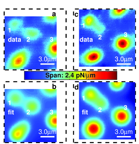
To confirm that the two stacks we manipulated compose one vortex, we fit the scan before annihilation [Fig. 2 (a),(b)]. The model we used is based on the fact that, for , the magnetic field from a stack of pancake vortices is approximately the field from a magnetic monopole residing beneath the superconducting surface Clem (1994). The flux associated with the vortex stack is . For a stack extending from depth up to the surface, . For a semi-infinite stack extending from depth down: Guikema et al. (2008). We find that our tip can be well approximated by a long narrow cylinder magnetized along its axis, . The MFM signal from a collection of vortex stacks is then given by the “monopole-monopole” model: , where enumerates the distinct vortex features in a scan, is the in-plane position of the tip; and where is the dipole moment per unit length, is the offset due to the tip geometry and the non-superconducting layer on the surface of the superconductor Auslaender et al. (2008)). The fit in Fig. 2(b) gives , confirming that two adjacent partial vortex stacks add up to one regular vortex.
Other experimental observations provide further insight about the kinked stacks. When we recombined and re-separated the same pair of stacks repeatedly, we could only manipulate one member. Presumably, this stack was the finite top stack. Furthermore, both the separation between the stacks and the signal amplitudes changed in the annihilation-creation process (e.g. Fig. 2), reasserting that pinning is important and that the tip allows the dragged pancakes to explore the pinning environment. Finally, partial pairs were rare [only one in Fig. 1(b)]. However, most other vortices had irregular shape, which we believe is due to misalignment of the pancakes, too small to be resolved as distinct stacks because of the relatively large . This irregularity tended to diminish after dragging, in support of the picture that pinning hinders pancake stacks from aligning.
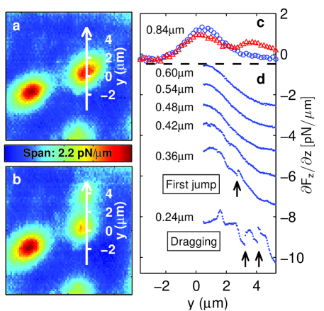
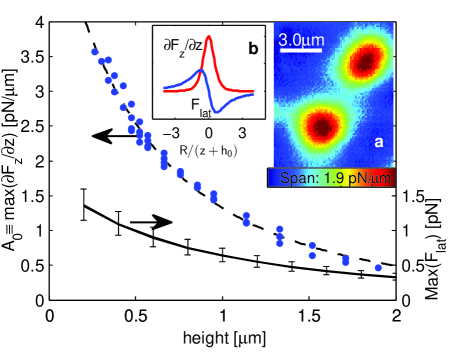
The deliberate annihilation and recreation of partial vortex pairs confirms the picture of kinked pancake stacks interacting with local pinning. To provide quantitative information on the coupling between the pancakes composing a single vortex, we measure the force required to create a kink (Fig. 3). To that end, we moved the tip repeatedly along a line leading away from a regular vortex at constant , approaching closer to the surface for each new line-scan to increase [Fig. 3(d)]. We estimate from the monopole-monopole model (Fig. 4). For large , the vortex remained unperturbed, implying . We estimate from the largest at which we observe vortex motion, manifesting itself as discontinuities in the scan trace well above the noise level (0.05 pN/). For example, at K we observed first motion at , giving pN. For lower scans (e.g. m), the tip dragged part of the vortex to a new position, creating two distinct stacks [Fig. 3(b)]. In order to pull a vortex apart, has to overcome both and the restoring force , which binds the two partial stacks together. At the position where the partial stack stopped following the tip, . Thus, the measured restoring force can be estimated from: giving pN for a stack separation of m, as identified by fitting Fig. 3(b) to the monopole-monopole model.
The restoring force, , has two contributions, both attractive: the magnetic coupling between pancakes in different layers and the Josephson-string line-tension. The former is obtained by summing over the magnetic interaction between all the pancakes in the two partial stacks. Benkraouda and Clem (BC) Benkraouda and Clem (1996) calculated this force for two stacks of equal length, long on the scale of . In our case, the length of the top stack, , is of order . For we obtain the BC result, suppressed by a factor of approximately , to give: . The line tension of a Josephson string for is: Clem (2004). Given m and m at K Broun et al. (2007); Hosseini et al. (2004), m and [from fitting Fig. 3(b)], we find pN and pN. Adding the two gives pN, in good agreement with our estimate from the measurement.
We manipulated 20 vortices at various temperatures near . For some we thermal-cycled above and slightly changed the applied magnetic field for a different initial vortex configuration. We successfully created and observed the kinked structure in two vortices. In the remaining cases we could drag the top of the vortex but did not observe kinking. This is not unexpected: by MFM we can only manipulate pancakes that lie at most a few beneath the surface because of the exponential suppression of the force from the tip. Imaging is also limited, because the MFM’s resolution is set by , the scale on which the field from a stack decays. The low rate of creating observable kinks in the limited volume defined by and (10%) and of observing as field-cooled partial stacks (one pair in 3 thermal-cycles) reasserts that the balance between local pinning and is crucial for determining the alignment of the pancakes composing a vortex. It also suggests that the distribution of pinning cites has spacial variation, but is not strongly inhomogeneous.
To conclude, by using MFM for imaging and manipulating individual vortices, we have verified that separated pancake stacks in the presence of pinning are the appropriate description for vortices in highly anisotropic type-II superconductors. We have measured the force required to depin a pancake stack and to create the kinked structure, providing quantitative information on the coupling between pancake stacks in a single vortex. The experiment highlights single vortex mechanical properties, hard to extract from macroscopic measurements. The technique, manipulating individual vortices by MFM, opens unique possibilities to study interacting many-body systems Nelson and Vinokur (1993), as well as to address open questions in vortex matter, e.g. the cutting barrier for vortices and vortex entanglement Nelson (1988); Reichhardt and Hastings (2004).
Acknowledgment: The authors would like to thank H. Bluhm and B. Kalisky for helpful discussions. The work is supported on DOE contract no. DE-AC02-76SF00515.
References
- Clem (1991) J. R. Clem, Phys. Rev. B 43, 7837 (1991).
- Artemenko and Kruglov (1990) S. N. Artemenko and A. N. Kruglov, Phys. Lett. A 143, 485 (1990).
- Clem (2004) J. R. Clem, J. Supercond. 17, 613 (2004).
- Bulaevskii et al. (1992) L. N. Bulaevskii, M. Ledvij, and V. G. Kogan, Phys. Rev. B 46, 11807 (1992).
- Blatter et al. (1994) G. Blatter, M. V. Feigel’man, V. B. Geshkenbein, A. I. Larkin, and V. M. Vinokur, Rev. Mod. Phys. 66, 1125 (1994).
- Beidenkopf et al. (2007) H. Beidenkopf, T. Verdene, Y. Myasoedov, H. Shtrikman, E. Zeldov, B. Rosenstein, D. Li, and T. Tamegai, Phys. Rev. Lett. 98, 167004 (2007).
- Figueras et al. (2006) J. Figueras, T. Puig, X. Obradors, W. K. Kwok, L. Paulius, G. W. Crabtree, and G. Deutscher, Nat. Phys. 2, 402 (2006).
- Moser et al. (1998) A. Moser, H. Hug, B. Stiefel, and H. Guntherodt, J. Magn. Magn. Matt. 190, 114 (1998).
- Straver et al. (2008) E. W. J. Straver, J. E. Hoffman, O. M. Auslaender, D. Rugar, and K. A. Moler, Appl. Phys. Lett. 93, 172514 (2008).
- Auslaender et al. (2008) O. M. Auslaender, L. Luan, E. W. J. Straver, J. E. Hoffman, N. C. Koshnick, E. Zeldov, D. A. Bonn, R. Liang, W. N. Hardy, and K. A. Moler (2008), to be appear on Nat. Phys.
- Benkraouda and Clem (1996) M. Benkraouda and J. R. Clem, Phys. Rev. B 53, 438 (1996).
- Guikema et al. (2008) J. W. Guikema, H. Bluhm, D. A. Bonn, R. Liang, W. N. Hardy, and K. A. Moler, Phys. Rev. B 77, 104515 (2008).
- Beleggia et al. (2004) M. Beleggia, G. Pozzi, A. Tonomura, H. Kasai, T. Matsuda, K. Harada, T. Akashi, T. Masui, and S. Tajima, Phys. Rev. B 70, 184518 (2004).
- Grigorenko et al. (2002) A. N. Grigorenko, S. J. Bending, A. E. Koshelev, J. R. Clem, T. Tamegai, and S. Ooi, Phys. Rev. Lett. 89, 217003 (2002).
- Grigorenko et al. (2001) A. Grigorenko, S. Bending, T. Tamegai, S. Ooi, and M. Henini, Nature 414, 728 (2001).
- Vlasko-Vlasov et al. (2002) V. K. Vlasko-Vlasov, A. Koshelev, U. Welp, G. W. Crabtree, and K. Kadowaki, Phys. Rev. B 66, 014523 (2002).
- Liang et al. (1998) R. Liang, D. Bonn, and W. Hardy, Physica C 304, 105 (1998).
- Hosseini et al. (2004) A. Hosseini, D. M. Broun, D. E. Sheehy, T. P. Davis, M. Franz, W. N. Hardy, R. Liang, and D. A. Bonn, Phys. Rev. Lett. 93, 107003 (2004).
- Broun et al. (2007) D. M. Broun, W. A. Huttema, P. J. Turner, S. Ozcan, B. Morgan, R. Liang, W. N. Hardy, and D. A. Bonn, Phys. Rev. Lett. 99, 237003 (2007).
- Liang et al. (2005) R. Liang, D. A. Bonn, W. N. Hardy, and D. Broun, Phys. Rev. Lett. 94, 117001 (2005).
- Albrecht et al. (1991) T. Albrecht, P. Grutter, D. Horne, and D. Rugar, J. Appl. Phys. 69, 668 (1991).
- (22) We used a commercial cantilever Nanosensors™SSS-QMFMR with tip radius of curvature nm.
- (23) The spring constant of the cantilever is measured by Sader’s method Sader et al. (1999).
- Clem (1994) J. R. Clem, Physica C 235, 2607 (1994).
- (25) The micron-size mostly comes from the sample non-superconducting layer, which developed as a result of extensive surface cleaning due to contamination.
- Nelson and Vinokur (1993) D. R. Nelson and V. M. Vinokur, Phys. Rev. B 48, 13060 (1993).
- Nelson (1988) D. R. Nelson, Phys. Rev. Lett. 60, 1973 (1988).
- Reichhardt and Hastings (2004) C. J. O. Reichhardt and M. B. Hastings, Phys. Rev. Lett. 92, 157002 (2004).
- Sader et al. (1999) J. Sader, J. Chon, and P. Mulvaney, Rev. Sci. Instrum. 70, 3967 (1999).