Beijing National Laboratory for Condensed Matter Physics, Beijing 100190, China
Intrinsic properties of magnetically ordered materials Occurrence, potential candidates General theory and models of magnetic ordering Theories and models of superconducting state
Striped antiferromagnetism and electronic structures of SrFeAsF and their implications
Abstract
We investigate structural, magnetic, and electronic properties of SrFeAsF as a new parent for superconductors using a state-of-the-art density-functional theory method. Calculated results show that the striped antiferromagnetic order is the magnetic ground state in the Fe layer and the interlayer magnetic interaction is tiny. Calculated As and Sr positions are in good agreement with experiment. There are only two quasi-two-dimensional bands near the Fermi level. The valence charge is mainly in the Fe and F layers, and the magnetic moment is confined to the Fe atoms. All the spin couplings within the Fe layer are antiferromagnetic due to the superexchange through the nearest As atoms. These results, with the record-equaling phase-transition temperature in the latest Sm-doped SrFeAsF, show that the SrFeAsF, sharing the same structure with LaFeAsO, is promising for achieving better superconductors.
pacs:
75.30.-mpacs:
74.10.+vpacs:
75.10.-bpacs:
74.20.-z1 Introduction
Fe-based superconductors attract more and more attention since superconductivity was found in doped LaFePO[1]. The advent of superconducting F-doped LaFeAsO stimulates a world-wide campaign for more and better Fe-based superconductors [2]. Replacing La by other lanthanides or doping with F has yielded more superconductors, and higher phase-transition temperatures () have been achieved in some of them [3, 4, 5]. Furthermore, much more superconducting materials were found by using other dopants and other parent compounds [6, 7, 8, 9]. Even FeSe can be made superconducting by applying high pressure [10, 11]. Now there are three series of FeAs-based superconductors: FeAsO (: lanthanide elements), Fe2As2 (: alkaline-earth elements), and LiFeAs. So far, the highest is 55-56 K in the case of doped SmFeAsO [5]. Their structural, magnetic, electronic properties are intensively investigated and the microscopic mechanism for the superconductivity in these materials has been explored [12, 13, 15, 14, 16, 17, 18, 19, 20, 21, 22, 23]. Very recently, superconductivity was found in Co and La doped SrFeAsF materials [24, 25, 26, 27]. SrFeAsF has the same crystal structure as FeAsO and similar magnetic instability, but does not include any lanthanide [28, 29, 30]. It has been found that Sm-doped SrFeAsF can become superconducting at 56 K, and higher transition temperatures should be reached with appropriate dopants [25, 26, 27]. Because some magnetic fluctuations are believed to mediate the superconductivity in FaAs-based materials, it is highly desirable to investigate the magnetic orders, electronic structures, and magnetic properties of the parent compound SrFeAsF.
Here, we use a state-of-the-art density-functional theory (DFT) method to investigate the structural, electronic, and magnetic properties of the SrFeAsF. Our total energy results show that the striped antiferromagnetic (AF) order, the same as that of LaFeAsO, is the magnetic ground state in the Fe layer, and the interlayer magnetic interaction is tiny. Our calculated position parameters of As and Sr are in good agreement with experiment. The electronic band result shows that there are only two quasi-two-dimensional (quasi-2D) bands near the Fermi level. Our charge and magnetization density analysis shows that the valence charge is mainly distributed in the Fe and F layers, and the magnetic moment is confined to the Fe layer. The spin couplings within the Fe layer are AF due to superexchange through the nearest As atoms. The real moment should be much smaller than the DFT value because of quantum spin fluctuations. More detailed results will be presented in the following.
2 Computational detail
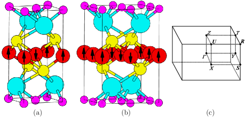
SrFeAsF usually assumes the tetragonal AsCrSiZr (tP8) structure with space group P4/nmm (No. 129) at high temperature. It transits to an orthorhombic distorted phase at 185 K, and furthermore, there is a magnetic instability at 175 K [28, 29]. A similar behavior has been observed in LaFeAsO [2, 12, 13]. We shall investigate by self-consistent calculations the possible magnetic structures of the two SrFeAsF phases shown in fig. 1. Figure 1a shows the structure with the familiar checkerboard AF (AF1) order and fig. 1b that with a striped AF (AF2) order. The interlayer magnetic interaction can be ferromagnetic (FM) or AF.
All the calculations are done using a full-potential linearized-augmented-plane-wave (FLAPW) method within the density-functional theory [31, 32], as implemented in the package WIEN2K [33, 34]. The generalized gradient approximation (GGA) to the exchange-correlation potential is used for the presented results [35], and local-density-approximation (LDA) calculations are done for comparison [36]. Full relativistic effects are calculated for core states, and the scalar relativistic approximation is used for valence states. The spin-orbit coupling [37] is neglected because it has little effect on the system. We use 400 k points in the first Brillouin zone for the two AF structures. We make the harmonic expansion up to =10 inside the atomic spheres. The radii of the muffin-tin spheres of Sr, Fe, As, and F are 2.3, 2.1, 2.2 and 2.0 atomic unit (a.u.), respectively. is set to 8.0. The self-consistent calculations are considered to be converged only when the integrated charge difference per formula unit between input and output charge density is less than 0.0001.
3 Results and discussion
We use the experimental lattice constants (,) = (3.9930Å,8.9546Å) for the tetragonal structure, and (,,) = (5.6155Å,5.6602Å,8.9173Å) for the orthorhombic structure [28, 29]. As for the internal position parameters of As and Sr atoms, we use (,) = (0.6527,0.1598) and (0.6494,0.1635) as input and optimize them in terms of forces standard (2 mRy/a.u.) for both of the structures [28, 29]. We obtain (,) = (0.6444,0.1634) and (0.6475,0.1637) for the AF1 and AF2 structures, respectively. For the AF2 structure, our GGA result, (0.6475,0.1637), is in good agreement with experiment [28, 29], in contrast to that from non-magnetic calculations [38, 39] and (0.6357,0.1624) of an LDA calculation of ours. The magnetic moment in the Fe sphere is 1.65 and 1.97 for the AF1 and AF2 phases. The total Fe moment in the AF2 phase is approximately 2, twice as large as an LDA result of ours. The parameters and and the magnetization density distributions do not change when we switch the interlayer magnetic interaction from FM to AF. The AF2 phase is lower by 80 meV in total energy per formula unit than the AF1 phase. This means that the striped AF2 phase is the ground-state phase, in agreement with experiment [28, 29]. The Fe spins align parallel along the (shorter) axis and antiparallel along the axis, which is the same as LaFeAsO [6, 17, 40]. SrFeAsF has the striped AF order as its ground state, the same as LaFeAsO [16, 17, 22, 23]. The energy difference of 80 meV of the AF1 phase is also comparable with the 75 meV for the checkerboard AF phase of LaFeAsO [16]. The moment of the magnetic ground state phase is approximately the same as that of LaFeAsO [16, 22, 23].
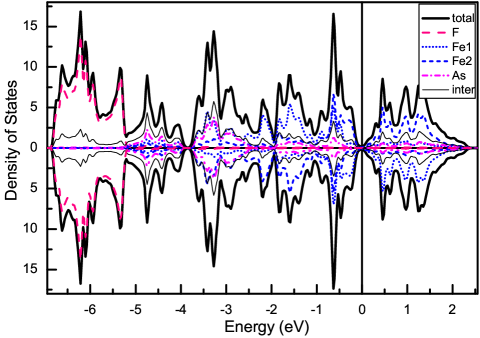
The total spin-dependent density of states (DOS) and those projected in the muffin-tin spheres of F, Fe1, Fe2, and As atom and in the interstitial region of the AF2 structure are presented in fig. 2. The filled states between -6.9 and 0 eV are the valence states from Fe-3d64s2, As-4p3, Sr-5s2, and F-2p5 orbitals. The semi-core states such as As-4s2 are lower than -10.7 eV. There is no energy gap in the energy window presented, but two pseudo-gaps are visible, at the Fermi level and -3.85 eV. The DOS between -6.9 and -5.2 eV, having symmetry between the two spin channels, mainly comes from F-2p states, and the Sr states almost disappear from the energy window presented. The As DOS is also almost symmetrical. Concerning spin, it is distributed between -5.2 and 2.5 eV, but its largest part is between -3.8 and -2.2 eV. It is clear that the Fe states are spin-split. Actually, we have two different Fe atoms: Fe1 and Fe2. Their spins are antiparallel. The spin-down part of the Fe1 DOS is mainly distributed between -1 and 2.5 eV and the spin-up part between -3.8 and -1 eV. The Fe2 DOS is equivalent to the Fe1 DOS with the two spin channels interchanged. One feature is a substantial DOS contribution from the interstitial region, which reflects substantial covalence between Fe and As. At the Fermi level, the DOS calculated without spin polarization is substantially larger than that of our spin-polarized calculation [38, 39]. Our DOS results are similar to spin-polarized GGA results of LaFeAsO [16].
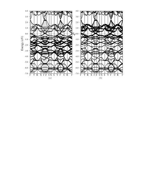
In fig. 3 we show the spin-dependent band structure with Fe1 character. The bands have very little dispersion along the axis. It is surprising that the band structure near the Fermi level is very simple, consisting of only two bands at the Fermi level. The band that has the maximum along -Z originates from the Fe1 dxy state, and the other the Fe1 d one. These two bands near the Fermi level have a much larger weight in the spin-down than in the spin-up channel. This implies that the electronic structure near the Fermi level is quasi-2D and spin-split. This special property is reasonable because the Sr atom is strongly ionic and the Fe moments align antiferromagneticaly along the axis. The band structure near the Fermi level is similar to that of LaFeAsO [16]. It is interesting that the band feature near the Fermi level along - is consistent with that obtained with a phenomenological two-band model [41]. Actually, the detailed band structure near the Fermi level depends sensitively on the structural parameters (,) and the magnetic moment [16, 22, 23]. When becomes smaller, the moment is correspondingly smaller and the band structure near the Fermi level looks more like that of non-magnetic calculations [38, 39, 18, 22].
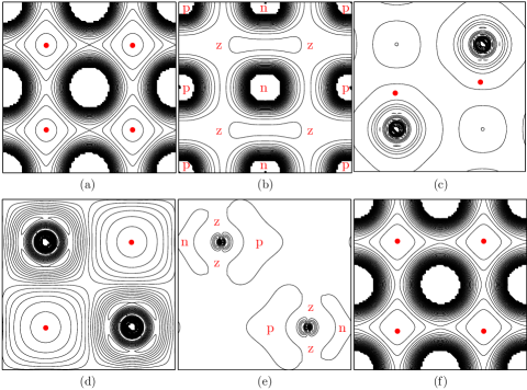
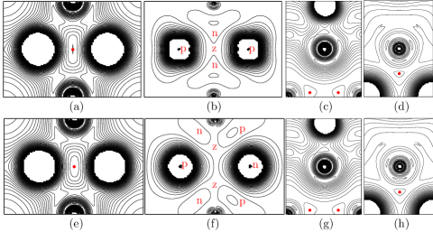
In fig. 4 we present the charge and magnetization density distributions in the planes defined by the two symmetrical bonds with the same vertex atom. The panels (a) and (e) show the charge density distributions in the two planes defined by the two different Fe-As-Fe chains, respectively, and the (b) and (f) the corresponding magnetization density distributions. One of the planes includes the axis and the other the axis. The panels (c) and (g) show the charge density distributions in the two planes defined by the two different Sr-As-Sr chains. The panels (d) and (h) show the charge density distributions in the two planes defined by the two different F-Sr-F chains, respectively. The red or gray dot in the charge plots labels the smallest charge density in /a.u.3 ( is the electron charge): 0.007 in (a), 0.003 in (c), 0.003 in (d), 0.006 in (e), 0.003 in (g), and 0.003 in (h). The lowest contours represent the charge density values in /a.u.3: 0.004, 0.007, 0.010, and so on. In the magnetization plots in (b) and (f), the red or gray letters ‘z’, ‘p’, and ‘n’ mean that the magnetization density in the region is zero, positive, and negative, respectively. The magnetization density values (in /a.u.3) of the contours near the zero are , , and so on. The magnetization density vanishes in these planes at the same places as in the panels (c), (d), (g), and (h), and thus this is not shown again.
In order to investigate the charge and magnetization density distributions as a whole, we present them by atomic layer in fig. 5. The panels (a) and (d) show the charge density distributions in the Fe and As planes, and the panels (b) and (e) the magnetization density distributions in the same planes. The panels (c) and (f) show the charge density distributions in the Sr and F planes, and the magnetization density in these two planes is near zero and thus not presented. The red or gray dots denote the smallest charge density in /a.u.3: 0.024 in (a), 0.0025 in (c), 0.006 in (d), and 0.0025 in (f). The letters ‘z’, ‘p’, and ‘n’ imply the same as in fig. 4. It is clear that the spin is mainly confined in the Fe layer and the magnetization density is nearly zero in the F layer and the adjacent two Sr layers. Therefore, the interlayer spin interaction must be tiny, which in return supports our computational model.
In addition, we have done the same DFT calculations assuming an AF order along the axis. The calculated total energies and position parameters of As and Sr are the same as those presented above. This is caused by the strong ionicity of the Sr layers and the zero magnetization density in the Sr and F layers. Actually, one cannot determine the magnetic order along the axis by using DFT calculations because the interlayer magnetic interaction is too weak. As for the spin order in the Fe layer, the spins align antiferromagnetically along the axis but ferromagnetically along the axis. The nearest spin coupling constants along the and axes, and , are AF. There is an AF coupling () between the next nearest Fe spins. Other inter-spin couplings are substantially smaller [42]. These three coupling constants are determined by the super-exchange through the bridging As atoms and other factors [40]. The small difference is caused by the structural distortion. As for the moment per Fe atom, our GGA and LDA results are nearly 2 and 1, much larger than the experimental value [30]. This situation is the same as that of LaFeAsO whose experimental moment per Fe atom is [12, 13], much smaller than from GGA calculations [22, 23]. For LaFeAsO, the large discrepancies can be reduced by using LDA rather than GGA in optimizing the crystal structure and calculating the moment, but this scheme leads to a large discrepancy of the calculated As position parameter from the experimental result [17, 22, 23]. On the other hand, spin-orbit coupling, monoclinic distortion, and p-d hybridization are used to obtain smaller value for the moment [21]. In fact, this situation, however, has not been settled even in the case of LaFeAsO. We believe that quantum many-body effects may play some important roles in determining the actual moment. For SrFeAsF, the actual magnetic moment is also much smaller than the GGA value and we also attribute this discrepancy to quantum many-body effects of the spin fluctuations. More investigations are in need to solve this moment problem without leading to other discrepancies.
4 Conclusion
In summary, we have investigated the structural, magnetic, and electronic properties of SrFeAsF using the state-of-the-art DFT method. Our total energy results show that the striped AF order is the magnetic ground state in the Fe layer and the interlayer magnetic interaction is tiny. The calculated As and Sr positions are in good agreement with experiment. There are only two quasi-2D bands near the Fermi level. The valence charge is mainly distributed in the Fe and F layers, and the magnetic moment is confined to the Fe atoms. All the intra-layer spin couplings are AF due to the superexchange through As atoms. SrFeAsF shares the main features of the structural, electronic, and magnetic properties with LaFeAsO. The actual moment is smaller than our value, which is the same as the situation for LaFeAsO and should be solved by considering quantum many-body effects. Because the Sm-doped SrFeAsF has equaled the record (56 K) of the FeAs-based superconductors, it is believed that higher will be realized in the SrFeAsF series. These results are useful for understanding the structural, electronic, and magnetic properties of SrFeAsF and should have implications achieving better superconductors by appropriate doping.
Acknowledgements.
BGL is grateful to H. H. Wen for informing him of the SrFeAsF series[24, 25, 29, 28]. This work is supported by Nature Science Foundation of China (Grant Nos. 10774180 and 10874232), by Chinese Department of Science and Technology (Grant No. 2005CB623602), and by the Chinese Academy of Sciences (Grant No. KJCX2.YW.W09-5).References
- [1] \NameKamihara Y., Hirano M., Yanagi H., Kamiya T., Saitoh Y., Ikenaga E., Kobayashi K., Hosono H. \REVIEWPhys. Rev. B772008214515.
- [2] \NameKamihara Y., Watanabe T., Hirano M., Hosono H. \REVIEWJ. Am. Chem. Soc. 13020083296.
- [3] \NameTakahashi H., Igawa K., Arii K., Kamihara Y., Hirano M., Hosono H. \REVIEWNature 4532008376.
- [4] \NameChen X. H., Wu T., Wu G., Liu R. H., Chen H., Fang D. F. \REVIEWNature4532008761.
- [5] \NameRen Z.-A., Lu W., Yang J., Yi W., Shen X.-L., Li Z.-C., Che G.-C., Dong X.-L., Sun L.-L., Zhou F., Zhao Z.-X. \REVIEWChin. Phys. Lett. 2520082215.
- [6] \NameSushko P. V., Shluger A. L., Hirano M., Hosono H. \REVIEWPhys. Rev. B 782008172508.
- [7] \NameShein I. R. Ivanocskii A. L.arXiv: 0806.0750 [cond-mat] 2008.
- [8] \NameYan J. Q., Kreyssig A., Nandi S., Ni N., Budko S. L., Kracher A., McQueeney R. J., McCallum R. W., Lograsso T. A., Goldman A. I., Canfield P. C. \REVIEWPhys. Rev. B782008024516.
- [9] \NameRen Z., Zhu Z., Jiang S., Xu X., Tao Q., Wang C., Feng C., Cao G., Xu Z. \REVIEWPhys. Rev. B782008052501.
- [10] \NameMizuguchi Y., Tomioka F., Tsuda S., Yamaguchi T., Takano Y.\REVIEWAppl. Phys. Lett. 932008152505.
- [11] \NameLi L., Yang Z. R., Ge M., Pi L., Xu J. T., Wang B. S., Sun Y. P., Zhang Y. H.arXiv: 0809.0128 [cond-mat] 2008.
- [12] \Namede la Cruz C., Huang Q., Lynn J. W., Li J., Ratcliff II W., Zarestky J. L., Mook H. A., Chen G. F., Luo J. L., Wang N. L., Dai P. \REVIEWNature4532008899.
- [13] \NameKlauss H.-H., Luetkens H., Klingeler R., Hess C., Litterst F. J., Kraken M., Korshunov M. M., Eremin I., Drechsler S.-L., Khasanov R., Amato A., Hamann-Borrero J., Leps N., Kondrat A., Behr G., Werner J., Buchner B.\REVIEWPhys. Rev. Lett. 1012008077005.
- [14] \NameIshibashi S., Terakura K., Hosono H.\REVIEWJ. Phys. Soc. Jap772008053709.
- [15] \NameHaule K., Shim J. H., Kotliar G.\REVIEWPhys. Rev. Lett.1002008226402.
- [16] \NameYin Z. P., Lebègue S., Han M. J., Neal B. P., Savrasov S. Y., Pickett W. E.\REVIEWPhys. Rev. Lett.1012008047001.
- [17] \NameYildirim T.\REVIEWPhys. Rev. Lett.1012008057010.
- [18] \NameSingh D. J. Du M. H.\REVIEWPhys. Rev. Lett.1002008237003.
- [19] \NameMazin I. I., Singh D. J., Johannes M. D., Du M. H. \REVIEWPhys. Rev. Lett.1012008057003.
- [20] \NameSefat A. S., McGuire M. A., Sales B. C., Jin R., Howe J. Y., Mandrus D.\REVIEWPhys. Rev. B772008174503.
- [21] \NameWu J., Phillips P., Castro Neto A. H.\REVIEWPhys. Rev. Lett.1012008126401.
- [22] \NameMazin I. I., Johannes M. D., Koepernik K., Singh D. J. \REVIEWPhys. Rev. B782008085104.
- [23] \NameCao C., Hirschfeld P. J., Cheng H.-P.\REVIEWPhys. Rev. B772008220506.
- [24] \NameMatsuishi S., Inoue Y., Nomura T., Hirano M., Hosono H.\REVIEWJ. Phys. Soc. Jpn. 772008113709.
- [25] \NameZhu X. Y., Han F., Cheng P., Mu G., Shen B., Wen H. H. \REVIEWEurophys. Lett. 85200917011.
- [26] \NameWu G., Xie Y. L., Chen H., Zhong M., Liu R. H., Shi B. C., Li Q. J., Wang X. F., Wu T., Yan Y. J., Ying J. J., Chen X. H.arXiv: 0811.0761v2 [cond-mat] 2008.
- [27] \NameNomura T., Inoue Y., Matsuishi S., Hirano M., Kim J. E., Kato K., Takata M., Hosono H.arXiv: 0811.4614 [cond-mat] 2008.
- [28] \NameTegel M., Johansson S., Weiss V., Schellenberg I., Hermes W., Pottgen R., Johrendt D.\REVIEWEurophys. Lett. 84200867007.
- [29] \NameHan F., Zhu X. Y., Mu G., Cheng P., Wen H. H.\REVIEWPhys. Rev. B782008180503R.
- [30] \NameBaker P. J., Franke I., Lancaster T., Blundell S. J., Kerslake L., Clarke S. J.\REVIEWPhys. Rev. B 792009060402.
- [31] \NameHohenberg P. Kohn W.\REVIEWPhys. Rev.1361964B864.
- [32] \NameKohn W. Sham L. J.\REVIEWPhys. Rev.1401965A1133.
- [33] \NameBlaha P., Schwarz K., Sorantin P., Trickey S. B. \REVIEWComput. Phys. Commun.591990399.
- [34] \NameBlaha P., Schwarz K., Madsen G. K. H., Kvasnicka D., Luitz J.WIEN2k (Karlheinz Schwarz, Techn. Universität Wien, Austria) (2001), ISBN 3-9501031-1-2.
- [35] \NamePerdew J. P., Burke K., Ernzerhof M.\REVIEWPhys. Rev. Lett.7719963865.
- [36] \NamePerdew J. P. Wang Y.\REVIEWPhys. Rev. B45199213244.
- [37] \NameMacDonald A. H., Pickett W. E., Koelling D. D. \REVIEWJ. Phys. C1319802675.
- [38] \NameNekrasov I. A., Pchelkina Z. V., Sadovskii M. V.\REVIEWJETP Lett. 882008679.
- [39] \NameShein I. R. Ivanovskii A. L.arXiv: 0810.4581 [cond-mat] 2008.
- [40] \NameMazin I. I. Schmalian J.arXiv: 0901.4790 [cond-mat] 2009.
- [41] \NameRan Y., Wang F., Zhai H., Vishwanath A., Lee D.-H.\REVIEWPhys. Rev. B792009014505.
- [42] \NameZhu L.-F. Liu B.-G.to be published elsewhere.