Reconnection and merging of positive streamers in air
Abstract
Pictures show that streamer or sprite discharge channels emerging from the same electrode sometimes seem to reconnect or merge though their heads carry electric charge of the same polarity; one might therefore suspect that reconnections are an artifact of the two-dimensional projection in the pictures. Here we use stereo-photography to investigate the full three-dimensional structure of such events. We analyze reconnection, possibly an electrostatic effect in which a late thin streamer reconnects to an earlier thick streamer channel, and merging, a suggested photoionization effect in which two simultaneously propagating streamer heads merge into one new streamer. We use four different anode geometries (one tip, two tips, two asymmetric protrusions in a plate, and a wire), placed 40 mm above a flat cathode plate in ambient air. A positive high voltage pulse is applied to the anode, creating a positive corona discharge. This discharge is studied with a fast ICCD camera, in many cases combined with optics to enable stereoscopic imaging. We find that reconnections as defined above occur frequently. Merging on the other hand was only observed at a pressure of 25 mbar and a tip separation of 2 mm, i.e., for a reduced tip distance of . In this case the full width at half maximum of the streamer channel is more than 10 times as large as the tip separation. At higher pressures or with a wire anode, merging was not observed.
1 Introduction
Streamers penetrate into undervolted gaps due to space charges and local field enhancement at their heads [1]; frequently they break up into trees with many branches. Streamer branches stretching out from the same electrode carry head charges of equal polarity and repel each other electrostatically. Such self avoiding behaviour is incorporated in phenomenological dielectric breakdown models, see, e.g. [2, 3, 4, 5]. On the other hand, streamers and leaders emerging from oppositely charged electrodes carry opposite head charges; therefore when propagating towards the opposite electrode, they attract each other electrostatically and frequently join one another along the way; this is seen, e.g., in lamp ignition [6, 7] as well as in the counter leaders stretching from tall structures upwards towards an approaching lightning leader [8].
However, there are three recent observations [9, 10, 11] that seem to violate this scheme: streamer or sprite channels emerging from the same electrode do not repel each other, but they seem to merge or reconnect.
The first type of events was reported by Briels et al. [9] in pulsed power experiments in a needle-to-plane electrode geometry. Here thick and thin positive streamers emerged from the needle anode. The thick ones are much faster than the thin ones (as quantified in [9, 12]) and start somewhat earlier, they reach the cathode plate and then seem to attract thin streamers that arrive later. The streamers seem to approach the earlies ones in an almost perpendicular direction. Such an event is shown in figure 6 of [9] and will be called reconnection; a similar event is shown in figure 5 below and in figure 7 of [13] and figure 10 of [14]. A physical mechanism for such an event is given in [9]: the originally positive thick streamer channel charges negatively after connecting to the cathode and therefore attracts the late positive streamer electrostatically.
The second type of events was seen by Grabowski et al. [10] and Winands et al. [13] in pulsed power experiments of either positive or negative polarity: many streamers emerged from a wire electrode, and sometimes two almost parallel streamers seemed to merge into a single one while propagating away from the wire. Such an event is shown in figure 5B of [10] and will be called merging; a similar event is shown in figure 10 below. It was also reported orally for the experiments discussed in [13, 14]. A physical mechanism for such merging was recently proposed by Luque et al. [15]: the non-local photoionization reaction in nitrogen-oxygen mixtures like air could generate so much ionization in the space between the streamer heads that the heads merge despite their electrostatic repulsion; the mechanism was demonstrated in three-dimensional computations of two streamers for varying gas density and nitrogen-oxygen ratio.
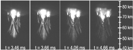
A third type of event was reported by Cummer et al. [11] in high speed images of sprite discharges above thunderclouds; the figures are reproduced in figure 8 below. Here sprite channels propagating downwards seem to connect to each other, often accompanied by a bright spot. Sprite discharges have been established to be large versions of streamers at low gas densities, related to each other by similarity laws [16, 17, 18]. This phenomenon looks quite similar to the reconnection described above, however, the sprite streamers do not reach any electrodes to change the channel polarity.
These three events were imaged with normal photography, i.e., in a two-dimensional projection of the full three-dimensional events. Therefore it is impossible to determine from the figures whether two streamer branches really do join, or whether they pass behind each other, and only the statistical analysis of many pictures can lead to such a conclusion. However, the true three-dimensional event can be reconstructed from stereo photography. This method was recently developed for streamers by Nijdam et al. [19] where it has been shown that such a method can be very successful in reconstructing the complete 3D streamer tree structure for streamer discharges with a limited number of streamer channels (less than 50). In the paper [19], one example of an event is given that looks like a streamer loop or reconnection in normal photography, but where the channels turn out to pass behind each other in the stereo photography. In the present paper, stereo photography is applied to several situations where streamers appear to reconnect or merge.
2 Experimental set-up
All experiments presented here have been performed in ambient air with a cathode-anode gap of 40 mm. Although the experiments have been conducted inside a vacuum-vessel, in many cases the front window of this vessel was removed so that the air was identical to the ambient air inside the laboratory. In cases where pressures below 1000 mbar were used, the front window was mounted and the vessel contents were flushed with ambient air. The same electrical circuit as described in [19] was used. With this circuit, a positive (cathode directed) corona discharge is created by discharging a capacitor with a fast switch. We use a spark-gap as switch. This results in a voltage pulse on a pointed tip or wire with a rise-time of about 20 ns, a maximum voltage between 6 and 55 kV and a decay time of a few microseconds. More information about this circuit and the discharge vessel can be found in [9] and [17].
2.1 (Stereo) imaging and image evaluation
The corona discharge produced by the circuit is imaged onto an intensified CCD-camera (Stanford Computer Optics 4QuickE) with a minimum gate time of 2 ns. The original camera frames of all images are 1360 by 1024 pixel, 14 bit gray-scale images. All camera images presented in this paper are false-colour representations of these original camera frames. Image processing and measurements (e.g. of streamer diameters) were done on the original full resolution 14 bit gray-scale frames.
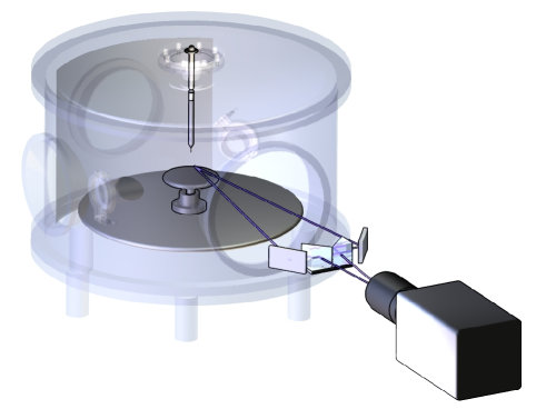
In most experiments, an optical system was positioned between the camera and the discharge in order to enable stereo photography. This optical system consists of two prisms and two mirrors as shown in figure 1. With this set-up we are able to produce stereoscopic images, as can be seen in figures 5, 7, 9 and 10. In order to reconstruct the 3D structure of (a part of) a streamer discharge, custom built software is used in which a line segment is placed manually over identical streamers in both left and right views. The xyz coordinates of the end points of this line are now calculated with a method described below.
Because we used a 40 mm gap instead of the 140 mm gap discussed in [19], the camera, prisms and mirrors have been placed closer to the vacuum vessel. The full angle between the two optical paths is 10 in all stereo measurements presented here.
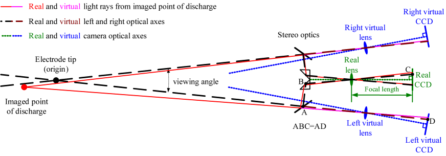
Another difference between the method described in [19] and the current method is the improved geometric reconstruction method. The present 3D reconstructions are obtained by using a complete 3D geometrical computation assuming a pin-hole camera. In this method, two virtual cameras are placed so that they will produce the left and right images without the prisms and mirrors as shown in figure 2. In other words, the distance between these cameras and the origin (on the vertical axis of the vacuum vessel) is equal to the total path length of one of the two paths drawn in figure 1. The angle between the two virtual cameras and the origin is equal to the angle between the two paths (10 in our case).
Both virtual cameras are represented as pinhole cameras; they consist of an infinitely small hole and a screen (the ICCD). In order to reconstruct a 3D location of a point, the vector from the pixel location of this point to the pinhole location is calculated for both cameras. The crossing point of these two vectors now determines its real 3D location. In real life measurements the vectors will of course never really cross in full 3D; therefore the point halfway between their closest points is used.
The assumption of a pinhole camera neglects lens artifacts like chromatic aberration and pincushion or barrel distortion. The earlier evaluations in [19] used a simpler model assuming two cameras far away from the system with a very large focal length. The present method reduces the absolute position errors of points far away from the origin (here defined as the position of one of the tips or an arbitrary position on the wire, see figure 2). The local errors (relative position errors of two points close together) have not changed significantly by employing the new method.
We estimate the error in absolute and relative position at around 2% and 0.5% of the vertical image size. In our set-up the vertical image size is roughly 50 mm. This means that the absolute error is about 1 mm and the relative error is about 0.3 mm.
If reconnection or merging occurs, it should be visible in both images of a stereoscopic photo. Furthermore, the vertical position of the merging/reconnection location should be the same in both images. If this is clearly the case then it can be concluded that the merging or reconnection really takes place. In many cases, this method has been used instead of the more labor intensive complete 3D reconstruction.
In some cases we have measured the width of the streamer channels. This is achieved with the following method: A line is drawn manually along a straight section of a streamer channel in a 2D camera image. Now a region is chosen that is large enough to easily encompass the whole channel, but not so large that it covers neighbouring channels. The pixel intensities of all pixels in this region are averaged along the direction of the line. This leads to an averaged crosscut profile of the streamer channel. From this profile, the base level is subtracted and then the full width at half maximum (FWHM) is determined.
2.2 Anode geometries
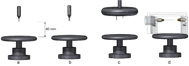
Four different anode geometries have been used; they are shown in figure 3: (a) a single tip, (b) symmetrical double tips, (c) asymmetrical double protrusions from a plane and (d) a wire. The difference between the double tip geometry (b) and the double protrusion geometry (c) is that in the double tip geometry, both tips extend from a pointed holder, while in the double protrusion geometry, the tips extend from a plane similar to the cathode plate. In this geometry, the background electric field at some distance from the protrusions is quite similar to a plane-plane geometry; it is quite homogeneous in contrast to a point plane geometry. This protrusion geometry (c) is roughly similar to a needle-array electrode [20, 21], but it has only two needles. In particular, we will use an asymmetric configuration where one tip extends significantly further out of the plane than the other.
The distance between the tip(s) or the wire and the cathode plate was always set to 40 mm. In the asymmetric geometry (c), 40 mm is the distance between the tip of the longer protrusion and the plane. The same tips have been used in all geometries, made of 1 mm diameter tungsten rods, with a conical pointed end. The tip radius is about 15 . The wire in the wire geometry is a 0.2 mm diameter kanthal wire.
2.3 Timings and delays
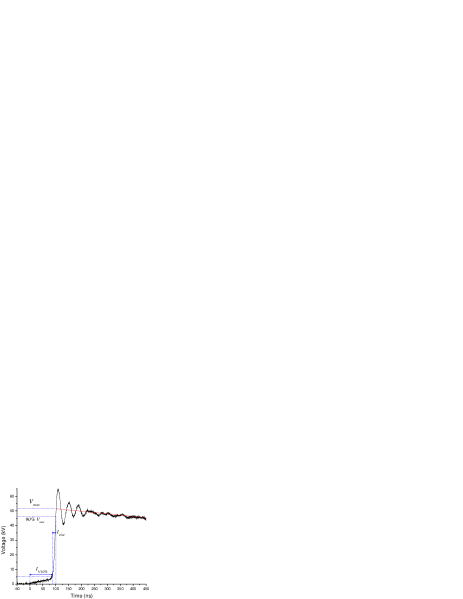
In order to properly correlate the timing of camera images to the voltage curve, a full analysis of all delays in our experimental set-up has been conducted. With the results of this analysis we can define an absolute timescale for all measurements. We define the origin of the time scale ( ns) as the moment when the voltage imposed on the anode starts to increase above 0 V. This is illustrated in figure 4.
The maximum voltage () is defined as the crossing point of the increasing voltage slope with a linear fit of the beginning of the decreasing voltage slope. In the case of figure 4 this leads to . The duration of the slow voltage increase just after ns (here about 80 ns) depends mainly on the pressure in the spark gap switch and, to a lesser extent, on the streamer vessel pressure and anode geometry. Therefore we have defined another important point: , the time when the voltage has reached . The rise-time () of the voltage slope is also important. We have defined it as the time between and . These characteristic values of the voltage pulse are influenced by resistors in the power supply and the impedance of the discharge and therefore vary between experiments.
The camera delay () is related to the same origin of the time scale as the voltage pulse. The camera gate is opened at and stays open for a specified time (). A more detailed discussion of the timing scheme can be found in the appendix.
3 Experimental results
3.1 Reconnection
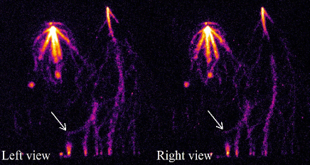
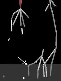
Streamer reconnection is studied in the single tip geometry (a) and in the double protrusion geometry (c) (see figure 3). Apparent reconnections in the single tip geometry (a) were observed and discussed before by Briels et al. [9], based on normal photography. A stereo image of a single tip streamer discharge with apparent reconnection(s) is shown in figure 5. A partial 3D reconstruction of this discharge is shown in figure 6.
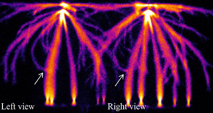
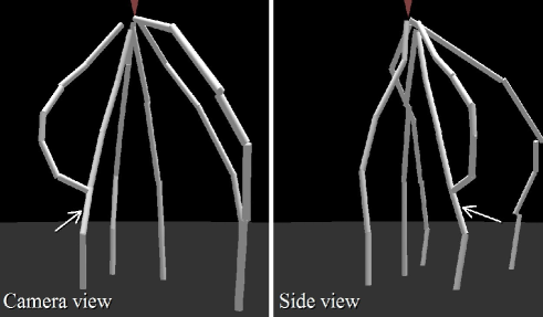
The stereo image already shows that reconnection occurs in both the left and right hand views at the same vertical position. This indicates that there is indeed a thin streamer channel reconnecting to a thick streamer channel. This is confirmed in the 3D reconstruction. It was found that reconnections as the one shown are observed in about 50% of the images taken under the conditions of figure 5. Because some images are not very clear and in some cases reconnecting streamer channels are obscured by other streamer channels, we conclude that reconnections occur in the majority of discharge events under these conditions.
Streamer reconnections can also be observed in the double protrusion anode geometry (c). In this geometry, the thickest and earliest streamer channels originate from the tip that protrudes farthest from the plane. An example of such a discharge event is shown in figure 7. This image shows multiple reconnections from streamer channels originating from the right tip to streamer channels originating from the left tip. (We continue to use the term reconnection as these streamers originate from the same electrode.) All these reconnections are clearly visible in both views and are therefore interpreted as real reconnections. The width (full width at half maximum, FWHM) of the thick, early channels is about 1.1 mm, the width of the thin channels about 0.6 mm. In figure 5 of [12], Briels et al. have reported similar values for the width of streamers created under these conditions.
Reconnections as shown in figures 5 and 7 are observed frequently under these experimental conditions. We find that reconnection only occurs to streamer channels that have crossed the entire gap and end on the cathode plate.
In figure 8, a sprite discharge is shown that remarkably resembles the streamer discharge shown in figure 7. Similar reconnection events are visible although it can not be proved that they are real because no stereo-photographic images are available. The similarities and differences between sprite and streamer reconnections will be discussed in more detail in section 4.
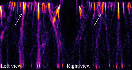
Briels et al. [17] have reported that thicker streamer channels are always faster than thin streamer channels. In our experiments, tens to hundreds of nanoseconds after the thick channels have bridged the gap, thinner and slower streamers can connect to the conducting traces left behind by the early thick streamers. This has been investigated by increasing the delay of the camera so that only the late streamers are visible. An example of such an image can be seen in figure 9. It shows that most of the length of the thick channels seen in figure 7 is no longer visible. Only the upper part (secondary streamers) and the cathode spots of these channels remain clearly visible. This can easily be understood by the fact that only the propagating head of a streamer channel emits a significant amount of radiation; therefore the channel behind the head is usually invisible or very dim after the head has passed cf. figure 1 in [1].
A striking feature in figure 9 is the streamer channel indicated with the arrow. This streamer channel seems to change direction instantaneously by about 90. These direction changes are observed in most images with longer delays under these experimental conditions. They appear very similar to the shape of the streamers reconnecting as in figure 7. Therefore, these direction changes are interpreted as streamer reconnection. This confirms that reconnection is indeed the attraction of a late streamer channel towards an earlier streamer channel.
3.2 Merging
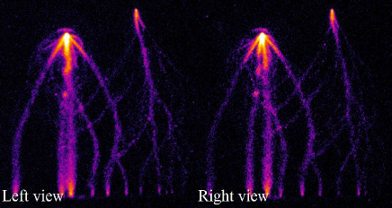
Streamer merging was first suggested as an interpretation of experiments in a wire-plate discharge. 2D pictures of Grabowski et al. [10] and Winands et al. [13] show possible merging of streamer channels close to the wire. We have reproduced such experiments with the wire-plate electrode geometry as shown in figure 3d. During this investigation, we have never found a definite case of merging of streamer channels in the hundreds of discharge events studied. Often channels seem to merge in one of the images, but are clearly not merging in the other image. An example of such an event is shown in figure 10. Here, in the left image two streamer channels seem to merge. However, the right image clearly shows that this is not the case.
The left image also shows that two channels propagate downwards from the apparent merge location towards the cathode plate. This is already an indication that no real merging occurs. In rare cases (less than 1% of the images), the image quality around an apparent merging location was not good enough to definitely conclude that no merging occurred, but the propagation of multiple channels from these locations again indicates that no merging occurs. The same conclusion is drawn from measurements at 400 mbar ambient air.
The average separation between streamers initiating from the wire in figure 10 is close to 2 mm. This value is in agreement with streamer observations in a wire-plane geometry of Winands et al. [22] and Creyghton et al. [23].
The streamer channels are more parallel in the wire-plate discharge than in the (double) tip-plate discharges. This is because the electric field lines diverge around the needle electrode in the projection plane of the picture while they are parallel for the wire electrode. However, in the direction perpendicular to the image plane, the streamers do diverge significantly and show similar spatial distributions as in the point-plane discharges. This divergence has been observed before by Winands et al. ([24], figure D6).
A more fundamental method to investigate streamer merging is to use two tips close to each other as shown in figure 3b. In this case streamer channels originate from both of these tips simultaneously (within 2 ns). These two streamer channels will now propagate in a more or less parallel direction towards the cathode plate and may merge or repel each other. Depending on pressure and other parameters, the two original streamer channels may also branch once or more. The chosen tip separation distance of 2 mm is similar to the average distance between streamers in the wire experiments at 1 bar. In our experiments both tips extend about 10 mm from the tip holder.
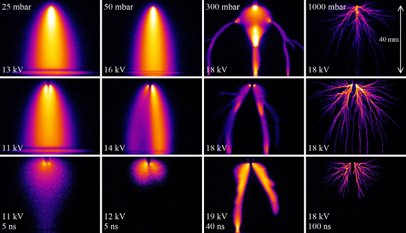
Images of streamer discharges originating from double tips are compared to images of streamers originating from a single tip in figure 11; the pressure varies from 25 mbar to 1000 mbar between the columns; the rows show single and double tip experiments with long exposure times and double tip experiments with short exposure times. The figure shows that for the double tip discharges, always two initial streamer channels are formed. These two channels repel each other for all pressures, except for 25 mbar where they merge. The width of the streamer (FWHM) is 23 mm at 25 mbar. This is 11.5 times as large as the distance between the two tips. At 50 mbar, the width of the single tip streamer is still 18 mm, 9 times the tip distance, but the streamers do not merge.
In cases when one of the streamers initiates shortly before the other (by any reason, randomly or systematically), it can shield the second streamer from the background electric field. This causes the second streamer to be less powerful than the first streamer. This can be observed in the 50 mbar double tip images. Here, it is clear that one streamer channel dominates the discharge and the other channel moves away from the central vertical axis. Which tip or side is dominant changes randomly from discharge to discharge and in some cases both channels are equally bright and symmetrically shaped. That one side often dominates the discharge, is observed for pressures between 50 and 250 mbar.
The images of figure 11 are taken with peak voltages of around 12 kV for the 25 mbar images to 18 kV for the 300 mbar and 1000 mbar images111It was attempted to use a fixed of 18 kV for all images. However, for pressures below 100 mbar, had to be decreased to prevent sparking in the top feedthrough of the set-up.. Also for other voltages the same merging behaviour as function of pressure was observed. At 25 mbar, merging still occurs with 6 kV peak voltage, while at higher pressures no merging is observed at both lower and higher voltages than the ones shown in figure 11.
4 Discussion and conclusions
From the images shown above and from all other images taken during these investigations, it can be concluded that reconnection of late streamer channels on earlier streamer channels occurs frequently in streamer discharges with many streamer channels. It is suggested [9] that the reconnection is caused by electrostatic attraction of a late streamer to a conducting channel left by an early streamer that already has reached the oppositely charged electrode and has changed polarity. The late streamer approaches the early channel almost perpendicularly — like an electrode plate or wire — which is another argument in favor of an electrostatic mechanism. In order to study reconnection of streamers theoretically, a complete three dimensional model would be required. Such streamer simulations, however, are only in the first stages of development [15, 25].
Besides electrostatic attraction, two other interaction mechanisms
between streamers can be imagined as the reason for reconnection:
magnetic attraction and photo-ionization. However, magnetic attraction
between current channels only occurs when these channels are more
or less parallel and would not lead to the near perpendicular reconnections
that are observed. Besides, the currents in these streamer channels
are low and would not lead to any significant Lorentz force. Photo-ionization
can also be excluded because decays exponentially like
for distances larger than the photo-ionization length
(at atmospheric pressure according to [26, 27]),
while electrostatic attraction decays as . Therefore
photo-ionization is much weaker at distances exceeding , and
can not turn the streamer path over large distances as in figures 5-7
and 9.
The reconnections in sprites [11] show a very similar signature, as a comparison of Figs. 8 and 7 shows: the head of a late sprite streamer is attracted to an earlier formed channel. However, no stereoscopic imaging is available in this case to decide whether the effect is real.
The similarity of sprites and streamers by now is well established,
see [17, 16, 18]. However,
there is another important difference, namely the early attracting
sprite channel is not connected to some electrode to explain its polarity
change. A possible mechanism is here a charge separation along the
sprite streamer channel; this hypothesis should be investigated in
future theoretical work.
Merging of more or less parallel, simultaneously propagating streamer channels was only observed at low pressures (25 mbar), but not at higher pressures under the conditions of these experiments (overvolted 40 mm gaps, ambient air, 2 mm or more tip separation). Only when the streamer diameter (FWHM) is at least 10 times larger than the tip separation, we observe merging. All observations show that thinner streamer heads always do repel each other and will remain separate while propagating between anode and cathode.
A mechanism for streamer merging was recently proposed by Luque et al. [15]; as photo-ionization in air is a nonlocal ionization reaction acting over a reduced length scale of about 1.6 mm bar at normal temperature, the ionization cloud around the streamer heads decays smoothly over this length scale. (The unit mm bar is used because the length scales of streamers are expected and observed to scale quite well with pressure [1, 17].) When the streamer heads get so close that their photoionization zones overlap, impact ionization can further enhance the ionization in the area between the heads and the streamer heads can merge. Again, magnetic attraction of parallel current carrying channels is very weak because of the low currents and can therefore be excluded.
We can compare the experimental results with the simulations of Luque et al. [25] on streamer merging due to photo-ionization. In these calculations, the pressure was varied while the reduced seed distance was fixed to at room temperature, here is the seed separation. Up to bar, the streamers in air always merged in these simulations. In the double tip measurements presented here, the real tip distance was fixed, therefore the reduced tip distance ranges from to . At 115 mbar, the 2 mm tip separation gives a reduced tip separation of , but the streamers repel each other; they merge only below . However, the streamers in the theoretical work emerge from an avalanche in a homogeneous electric field, while the streamers in the present experiments emerge from two needle electrodes. Therefore a discrepancy by a factor of 2 or more is not unreasonable, and we conclude that experiments and theory need to be developed further before they can be compared quantitatively. Furthermore, the theoretical prediction relies on the photo-ionization lengths that were measured by Penney and Hummert in 1970 [26] and whose accuracy is widely doubted [28, 29, 30]; but no other data are available.
Streamers in experiments are never initiated exactly simultaneously. We observe that inception of the different streamer channels occurs within 2 ns but we can not be certain that there is no jitter on smaller timescales. In the double tip experiments we can be certain that there is not one favorite tip because the dominant streamer changes from left to right and back randomly between discharge events. We can however, not be certain that there is no stochastic jitter in the inception times. This can lead to two streamers with a small mutual delay that also could prevent merging. If this is the case, it will probably be always present in real world experiments. Numerical simulations can answer if a time delay of e.g. 1 ns between two streamers will prevent merging. Such a time delay between inception can also be responsible for the appearance of a dominant and a weaker streamer channel; the streamer that is initiated first shields the second streamer from the background electric field.
In wire-plate discharges, apparent streamer merging is occasionally observed on 2D-images. However, in these discharges we have never observed merging with any degree of certainty with stereo-photography.
Appendix. Timing scheme of the experiment
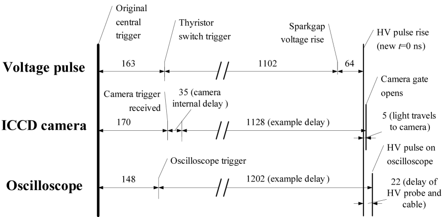
In order to determine the timing characteristics of the set-up, a full analysis of all timings and delays has been performed. In this analysis, the delays of all cables, optical fibres, probes and other equipment has been determined and combined. A sketch is shown in figure 12. In this figure, three time paths for different parts of the set-up are shown. These three time paths are all initiated by a central trigger from a function generator. Details of the time paths will be discussed below.
Voltage pulse
From the central trigger, the trigger pulse is fed through coaxial cables and an optical fibre to the thyristor switch in the high voltage circuit. This takes 163 ns. The thyristor switch in turn triggers the spark-gap 1102 ns later. The spark-gap then causes the rise of the high voltage pulse on the anode with a 64 ns delay. All three sections in this time-path have fixed delays with jitter of maximum 2-3 ns. These delays are intrinsic properties of the cables and equipment.
ICCD Camera
The ICCD camera is also triggered from the central trigger through coaxial cables and an optical fibre. This takes 170 ns. After receiving this trigger, the camera has an internal delay of 35 ns before it can open the gate. From this moment, the gate is opened after a user-specified delay. In the example from figure 12, this delay is set to 1128 ns in order to capture the beginning of the voltage pulse and the streamer initiation. Because of the short time-scales involved, we must account for the path-length of the light rays traveling from the discharge to the camera.
Oscilloscope
Again, the oscilloscope is triggered from the central trigger through coaxial cables and an optical fibre. This takes 148 ns. The rise of the high voltage pulse will occur some time after this trigger; in our example 1180 ns. Because the oscilloscope is connected to a high voltage (HV) probe with a long coaxial cable, the voltage rise will be detected on the oscilloscope 22 ns later.
Resulting timing
By using the known and set delays of the set-up, we can redefine a new origin of the time-scale that is the same for both the oscilloscope and the camera as is explained in section 4. In the example from figure 12, we have to subtract 74 ns from the time as shown on the oscilloscope to convert this to the time-scale of the camera. In other words, an event occurring at the new will be registered on the oscilloscope at 1128 ns and on the camera at 1202 ns.
References
References
- [1] U Ebert, C Montijn, T M P Briels, W Hundsdorfer, B Meulenbroek, A Rocco, and E M van Veldhuizen. The multiscale nature of streamers. Plasma Sources Science and Technology, 15:S118, 2006.
- [2] L Niemeyer, L Pietronero, and H J Wiesmann. Fractal dimension of dielectric breakdown. Physical Review Letters, 52:1033, 1984.
- [3] L Niemeyer, L Ullrich, and N Wiegart. The mechanism of leader breakdown in electronegative gases. IEEE Transactions on Electrical Insulation, 24:309, 1989.
- [4] V P Pasko, U S Inan, and T F Bell. Mesosphere-troposphere coupling due to sprites. Geophysical Research Letters, 28:3821, 2001.
- [5] M Akyuz, A Larsson, V Cooray, and G Strandberg. 3D simulations of streamer branching in air. Journal of Electrostatics, 59:115, 2003.
- [6] A Sobota, E M van Veldhuizen, and W W Stoffels. Discharge ignition near a dielectric. IEEE Transactions on Plasma Science, 36:912, 2008.
- [7] M Czichy, T Hartmann, J Mentel, and P Awakowicz. Ignition of mercury-free high intensity discharge lamps. Journal of Physics D: Applied Physics, 41:144027, 2008.
- [8] E M Bazelyan, Y P Raizer, and N L Aleksandrov. Corona initiated from grounded objects under thunderstorm conditions and its influence on lightning attachment. Plasma Sources Science and Technology, 17:24015, 2008.
- [9] T M P Briels, J Kos, E M van Veldhuizen, and U Ebert. Circuit dependence of the diameter of pulsed positive streamers in air. Journal of Physics D: Applied Physics, 39:5201, 2006.
- [10] L R Grabowski, T M P Briels, E M van Veldhuizen, and A J M Pemen. Streamers in pulsed positive corona: low and high current regimes. Proceedings of the 27th ICPIG Conference (Eindhoven), 27:04–425, 2005.
- [11] S A Cummer, N Jaugey, J Li, W A Lyons, T E Nelson, and E A Gerken. Submillisecond imaging of sprite development and structure. Geophysical Research Letters, 33:L04104, 2006.
- [12] T M P Briels, J Kos, G J J Winands, E M van Veldhuizen, and U Ebert. Positive and negative streamers in ambient air: measuring diameter, velocity and dissipated energy. Journal of Physics D. Applied Physics, 41:234004, 2008.
- [13] G J J Winands, Z Liu, A J M Pemen, E J M van Heesch, K Yan, and E M van Veldhuizen. Temporal development and chemical efficiency of positive streamers in a large scale wire-plate reactor as a function of voltage waveform parameters. Journal of Physics D: Applied Physics, 39:3010, 2006.
- [14] G J J Winands, Z Liu, A J M Pemen, E J M van Heesch, and K Yan. Analysis of streamer properties in air as function of pulse and reactor parameters by iccd photography. Journal of Physics D: Applied Physics, 41:234001, 2008.
- [15] A Luque, U Ebert, and W Hundsdorfer. Interaction of streamer discharges in air and other oxygen-nitrogen mixtures. Physical Review Letters, 101:075005, 2008.
- [16] V P Pasko. Red sprite discharges in the atmosphere at high altitude: the molecular physics and the similarity with laboratory discharges. Plasma Sources Science and Technology, 16:S13, 2007.
- [17] T M P Briels, E M van Veldhuizen, and U Ebert. Positive streamers in air and nitrogen of varying density: experiments on similarity laws. Journal of Physics D. Applied Physics, 41:234008, 2008.
- [18] H C Stenbaek-Nielsen and M G McHarg. High time-resolution sprite imaging: observations and implications. Journal of Physics D: Applied Physics, 41:234009, 2008.
- [19] S Nijdam, J S Moerman, T M P Briels, E M van Veldhuizen, and U Ebert. Stereo-photography of streamers in air. Applied Physics Letters, 92:101502, 2008.
- [20] K Takaki, M Hosokawa, T Sasaki, S Mukaigawa, and T Fujiwara. Production of atmospheric-pressure glow discharge in nitrogen using needle-array electrode. Applied Physics Letters, 86:151501, 2005.
- [21] A V Krasnochub, E I Mintoussov, M M Nudnova, and A Y Starikovskii. Interference between streamers in bunch of streamers. In Proceedings of the XXVIIth ICPIG, volume 27, pages 04–312, Eindhoven, The Netherlands, 2005. (published online at http://www.icpig2005.nl/).
- [22] G J J Winands, Z Liu, E J M van Heesch, A J M Pemen, and K Yan. ADS and CDS streamer generation as function of pulse parameters. IEEE Transactions on Plasma Science, 36:926, 2008.
- [23] Y L M Creyghton and E M van Veldhuizen. Diagnostic techniques for atmospheric streamer discharges. IEE Proceedings Science, Measurement & Technology, 141:141, 1994.
- [24] G J J Winands. Efficient Streamer Plasma Generation. PhD thesis, Technische Universiteit Eindhoven, 2007. (published online at: http://alexandria.tue.nl/extra2/200710708.pdf).
- [25] A Luque and U Ebert. Interacting streamers in air: The evolution of the space-charge layer in their heads. IEEE Transactions on Plasma Science, 36:914, 2008.
- [26] G W Penney and G T Hummert. Photoionization measurements in air, oxygen, and nitrogen. Journal of Applied Physics, 41:572, 1970.
- [27] M B Zhelezniak, A K H Mnatsakanian, and S V Sizykh. Photoionization of nitrogen and oxygen mixtures by radiation from a gas discharge. High Temperature, 20:357, 1982.
- [28] S Pancheshnyi. Role of electronegative gas admixtures in streamer start, propagation and branching phenomena. Plasma Sources Science and Technology, 14:645, 2005.
- [29] A Luque, U Ebert, C Montijn, and W Hundsdorfer. Photoionization in negative streamers: Fast computations and two propagation modes. Applied Physics Letters, 90:081501, 2007.
- [30] M M Nudnova and A Y Starikovskii. Streamer head structure: role of ionization and photoionization. Journal of Physics D: Applied Physics, 41:234003, 2008.