Sizing of Hall effect thrusters with input power and thrust level: An Empirical Approach
Abstract
Sizing methods can be used to get a first estimate of the required Hall thruster dimensions and operating conditions for a given input power and a corresponding thrust level. After a review of the existing methods, a new approach, which considers the three characteristic thruster dimensions, i.e. the channel length, the channel width and the channel mean diameter as well as the magnetic field, is introduced. This approach is based on analytical laws deduced from the physical principles that govern the properties of a Hall effect thruster, relying on a list of simplifying assumptions. In addition, constraints on the channel wall temperature as well as on the propellant atom density inside the channel are taken into account. The validity of the scaling laws is discussed in light of a vast database that comprises 23 single-stage Hall effect thrusters covering a power range from 10 W to 50 kW. Finally, the sizing method is employed to obtain a preliminary geometry and the magnetic field strength for a 20 kW and a 25 kW Hall effect thruster able to deliver a thrust of 1 N, respectively 1.5 N.
† ICARE, CNRS, 1C avenue de la Recherche Scientifique, 45071 Orléans, France.
To be published in Journal of Technical Physics 49, vol. 3-4 (2008).
Nomenclature
| channel cross section; area | |
| magnetic field strength | |
| analytic proportionality coefficient for | |
| empiric proportionality coefficient for | |
| analytic proportionality coefficient for | |
| empiric proportionality coefficient for | |
| analytic proportionality coefficient for | |
| empiric proportionality coefficient for | |
| , , | mean, external and internal channel diameter |
| grey body configuration factor | |
| channel width | |
| discharge current, ion current | |
| current corresponding to the propellant mass flow rate | |
| specific impulse | |
| Boltzmann constant | |
| channel length | |
| propellant atom mass, ion mass, electron mass | |
| propellant mass flow rate through the anode, ion mass flow rate | |
| atom, electron and ion number density | |
| input power | |
| power losses due to plasma-wall interactions | |
| heat flux deposited by the plasma onto channel walls | |
| , | inner, respectively outer, channel radius |
| electron and ion Larmor radius | |
| thrust | |
| maximum, external and internal wall temperature | |
| electron temperature | |
| discharge voltage | |
| thermal velocity of atoms, electrons and ions | |
| average ion exhaust velocity | |
| propellant conversion efficiency | |
| ratio between ionization mean free path and channel length | |
| voltage losses | |
| emissivity | |
| thrust efficiency | |
| ionization and electron-electron collision mean free path | |
| electron gyrofrequency | |
| electron-atom collision frequency | |
| scaling index variable | |
| cross-section for ionization and electron-electron impact | |
| electron-atom momentum exchange cross-section | |
| gyroperiod | |
| electron-atom collisional time |
1 Introduction
Electric propulsion is nowadays a well-established technology for space applications [1]. Among all proposed electric propulsive devices such as arcjet, magnetoplasmadynamic thruster, gridded ion engine and Hall Effect Thruster (HET), the latter is currently recognized as an attractive propulsion means for long duration missions and for maneuvers that require a large velocity increment. Hall effect thrusters, also called Stationary Plasma Thrusters or closed electron drift thrusters, are advanced propulsion devices that use an electric discharge with magnetized electrons to ionize and accelerate a propellant gas [2, 3]. Due to interesting features in terms of propellant ejection speed, efficiency, flexibility and lifetime, HETs are now employed for missions like geo-stationary satellite orbit correction and station keeping. Moreover, HETs appear as good candidates to be used as the primary propulsion engine for space probes during interplanetary journeys, as demonstrated by the successful SMART-1 Moon flyby solar-powered mission of the European Space Agency [4].
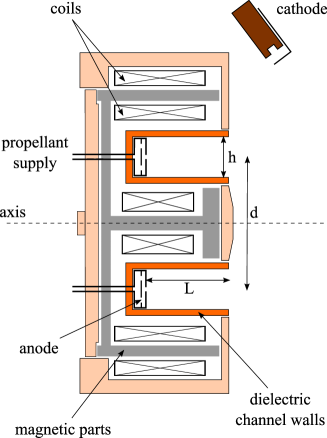
A schematic of a Hall effect thruster is depicted in Fig. 1. The basic physics of a HET implies a magnetic barrier and a low pressure DC discharge generated between an external hollow cathode and an anode in such a way that a crossed electric and magnetic fields discharge is created [2, 5, 6]. The anode, which also serves as gas injector, is located at the upstream end of a coaxial annular dielectric channel that confines the discharge. Xenon is generally used as a propellant gas for its specific properties in terms of high atomic mass and low ionization energy. A set of solenoids provides a radially directed magnetic field B of which the strength is maximum in the vicinity of the channel exhaust. The magnetic field is chosen strong enough to make the electron Larmor radius much smaller than the discharge chamber length, but weak enough not to affect ion trajectories. The electric potential drop is mostly concentrated in the final section of the channel owing to the low electron axial mobility in this restricted area. The corresponding induced local axial electric field E has two main effects. First, it drives a high electron azimuthal drift – the Hall current – that is responsible for the efficient ionization of the supplied gas. Second, it accelerates ions out of the channel, which generates thrust. The ion beam is neutralized by a fraction of electrons emitted from the hollow cathode. When operating near 1.5 kW, a HET ejects ions at 20 km s-1 and generates 100 mN of thrust with an overall efficiency of about 50 %.
New fields of application are nowadays envisaged for electric propulsion systems that require low and high power devices. Low power Hall thrusters ( 100 W) are well suited for drag compensation of observation satellites that operate on a low-altitude orbit in the Earth atmosphere as well as for orbit correction and orbit transfer of small platforms. The use of high power ( 5 kW) Hall thrusters for orbit raising and orbit topping maneuvers of communication satellites would offer significant benefits in terms of launch mass, payload mass and operational life. In addition, journeys towards far-off planets and asteroids with large and heavy robotic probes necessitate to build thrusters with an input power in the range 10-100 kW. In view of the projects demand, it appears necessary to expand the operating envelope of existing Hall effect thruster technology to achieve the required performance level. A non-trivial question then arises: How to extrapolate the design and architecture of currently existing Hall thrusters towards different scales and different operating conditions? In other words, what are the scaling laws that connect Hall effect thruster characteristic dimensions with operating parameters like discharge voltage, propellant mass flow rate and magnetic field strength and performances in terms of thrust, specific impulse and overall efficiency?
Scaling laws that govern the physical properties, the accelerating ability as well as propellant and energy consumption of Hall thrusters have been extensively investigated by numerous authors since the period of development of Hall thrusters in the 70’s. In spite of decades of research on this subject, the assessment of scaling laws is still a topic of great interest with debates and controversies as various methodologies and results exist. Therefore, before describing the approach associated with this study as well as its outcomes, it is worth briefly reviewing works carried out on this topic during the past few years and available in the literature. According to the pioneer works of the Russian physicist A. Morozov [5], in order to derive scaling laws, it is necessary to find a similarity criterion, or a set of criteria, that warrant the underlying physical processes stay unchanged whatever the truster. This principle states that the properties of thrusters with a different geometry are linked by way of scaling laws only if a sufficiently large number of dimensionless similarity criteria coincide. The complete set of similarity criteria has not yet been found, however, all works show that the Melikov-Morozov criterion has a strong impact on HET behavior and characteristics and it must always be taken into account. This criterion indicates that . In addition to similarity criteria, the investigation of scaling laws for Hall thrusters necessitates to account for simplifying assumptions, e.g. a frozen electron temperature, and constraints like a high efficiency and a reasonable channel wall temperature.
V. Zhurin and co-workers propose a size scaling method which is limited to the effects of changing either the channel width or the channel mean diameter [2]. One assumption is that the channel mean diameter is much larger than the channel width, so that variation of parameters in the radial direction are negligible. Furthermore, they considered a fixed discharge voltage. In order to obtain similar performances for two different thruster configurations, authors shown that the ratio of , and to must stay the same for the two configurations. Using these criteria and a set of assumptions they demonstrate that the magnetic field strength is inversely proportional to the channel width, , whereas the discharge current and the propellant mass flow rate are inversely proportional to the channel mean diameter, and .
The method presented by J. Ashkenazy et al. concerns low power scaling and it is based on the idea of a sufficient propellant utilization [7]. They show by means of a simplified analysis that a straightforward approach for scaling down the channel size results in a rise of power losses and a reduced overall thruster efficiency. To avoid these effects, the acceleration region has to be scaled down along with the channel width and the magnetic field strength must be increased in proportion to . They also describe an alternative view that consists in extending the channel length.
M. Martinez-Sanchez et al. propose an approach for low-power Hall effect thrusters that includes the use of reference points [8]. The goal is to achieve a reduction in the thrusters length scale while preserving both the thrust efficiency and the specific impulse. The main result of their study is that the propellant mass flow rate and the applied power scale as the channel length, and , whereas the magnetic field strength is in inverse proportion to the latter, . This scaling method allows to calculate the channel size and the performances of a small thruster with a given input power provided that a well-known thruster is utilized as a reference.
The team led by M. Andrenucci suggests to employ an analytical model coupled to an existing Hall thruster database [9]. This scaling methodology aims to provide design options for high power thrusters. The idea is to create a vector of fundamental parameters defining the thruster geometry and its performances. This vector is composed of three geometric parameters (, and ), the gas number density in the injection plane and the applied discharge voltage . A scaling matrix derived from the Hall thruster physical principles allows to obtain a new thruster characteristics on the basis of a reference thruster.
In a recent article [10], Daren Yu et al. present an improvement of the existing scaling theory by introducing a scaling index variable. They assume that the electron temperature and the discharge voltage are constant, that the ratio is constant and that the geometric similarity is given by =constant and =constant, where and are the channel outer respectively inner radius and represents a scaling index variable. They show by way of a comparison of experimental data with numerical outcomes for different values of , that results obtained from their scaling theory agree well with the experimental data for =2. Therefore they deduce that the number density is constant, whereas the mass flow rate , the input power , the thrust and the discharge current are proportional to the square of the outer channel radius .
Finally, it was demonstrated by V. Kim [6] that to reach a
high level of efficiency it is not only necessary to ionize and
accelerate ions but to accelerate them into the proper direction,
hence the need for an optimized magnetic field topology. In short,
for a HET with an optimized magnetic field map, there is a
relationship between the acceleration layer length and the
magnetic layer characteristic size and between and .
The use of these similarity criteria, which include the magnetic
field structure, permits to simplify the development of new Hall
thrusters models. V. Kim et al also emphasize the fact that in the
case of a traditional HET design, the ratio of the ionization mean
free path to the channel length must stay constant (Melikov-Morozov criterion) [11]. Moreover they give
additional criteria about the geometry of thruster elements, i.e.
and are both proportional to , that are equivalent to the
ones given by V. Zhurin. There are two immediate consequences.
First, the propellant mass flow density and the power density rise
when the thruster size decreases, assuming a constant discharge
voltage. Second, as the magnetic field strength is connected with
the characteristic dimensions, notably the channel width, and with
the operation mode, the magnetic field magnitude must rise when the
size
reduces in order to keep comparable conditions.
In this contribution, we propose an original way to extrapolate Hall thruster geometry towards both the low and high power ranges. The approach is based on the combination of a set of scaling laws with a vast body of existing data. Besides, realistic constraints on the performance level and on the thermal load allow to refine the set of possible , and characteristic scale lengths found for a given thruster input power. In section 2, similarity criteria and scaling laws are derived from the physics at work in a HET and, consequently, relationships between performances, operating parameters and the characteristic dimensions are established. The thermal constraint is discussed in section 3 along with modeling of thruster thermal behavior. A detailed description of the database on Hall thruster performances and properties is given in section 4. Besides, recorded data are compared with calculation outcomes. In section 5, our approach is finally employed to design a 20 kW as well as a 25 kW thruster. A summary and general conclusions follow in section 6.
2 Set of governing relations
2.1 Similarity criteria and scaling laws
A necessary first step in order to
determine scaling laws for Hall effect thruster does consist in
finding some critical parameters as well as in defining similarity
criteria based on the current knowledge and understanding of the
physics of Hall thrusters. The geometry of a Hall effect thruster is
defined by three characteristic dimensions, see
Fig. 1, the discharge channel length L, the
mean channel diameter and the
channel width h, as well as by a set of operating parameters
such as the magnetic field strength B, the discharge voltage
and the propellant mass flow rate .
To simplify the assessment of scaling laws, the following
assumptions have been made throughout the entire paper:
-
-
the electron temperature is constant and homogeneous whatever the operating conditions,
-
-
the propellant gas has a uniform temperature all over the channel, hence a constant propellant velocity,
-
-
the potential energy is fully converted into kinetic energy and all ions experience the whole potential drop, of which the magnitude is ,
-
-
plasma-wall interactions are taken into account through heat load to the channel walls,
-
-
the magnetic field is uniform; its value at the exit plane is solely considered,
-
-
electron transport across the magnetic barrier is considered as classical: no anomalous transport is accounted for within the region of strong magnetic field [12],
-
-
there are no multiply-charged ions in the plasma,
-
-
a parallel monokinetic ion beam is produced, i.e. the plasma jet divergence is null.
The first relationship reflecting the impact of the thruster scale on its performance is the relationship between the discharge channel length L and the ionization mean free path . To ensure a sufficient ionization of the gas, it is necessary to satisfy the Melikov-Morozov criterion:
| (2.1) |
The ionization frequency that originates from electron-atom impacts reads:
| (2.2) |
The ionization length, which corresponds to the mean distance an atom can travel before being ionized, can be formulated as the product in a first order approximation. Therefore the Melikov-Morozov criterion can be expressed as:
| (2.3) |
Assuming that both the electron temperature and the propellant speed are constant and independent of the operation conditions, implies that and , being only a function of , remain constant. To keep the ratio constant, equation 2.3 leads to:
| (2.4) |
In the same way, the ratio must stay constant, where is electron-electron impact mean free path:
| (2.5) |
where the cross-section is a function of the Coulomb logarithm [14]. The equation 2.5 implies that:
| (2.6) |
The relations 2.4 and 2.6 for the atom, respectively the electron, number density are the same than those developed before by V. Zhurin and M. Martinez-Sanchez [2, 8]. Another relation between and Hall thruster dimensions can be established when considering the propellant mass flow rate passing through the anode. The quantity can be decomposed into the product of several terms:
| (2.7) |
The annular channel cross section is given by:
| (2.8) |
hence . We can therefore consider that for a constant gas mass flow rate:
| (2.9) |
This second relationship between the atom number density and the
thruster dimensions and has never been mentioned previously,
as authors never considered two sizes at the same time. Note that,
in order to keep the physical processes at work in a Hall effect
thruster unchanged, to warrant a high efficiency and to limit the
thermal load as well as the channel wall wear, the number densities
of electron and atoms must stay roughly fixed inside the thruster
channel whatever the input power. The average values commonly found
in literature, which turn out to guarantee a satisfying operation,
are:
m-3 and m-3.
Another interesting fact is that the variables , an are
linked to one another. Indeed, by using the Melikov-Morozov
criterion and the mass flow rate definition, it comes:
Combining the two previous relations, one finds:
| (2.10) |
Therefore, for a fixed value of the parameter, and under our
list of assumptions, the thruster characteristic dimensions are
coupled through the gas mass flow
rate.
The magnetic field strength in a Hall effect thruster is such that electrons are magnetized and ions are not magnetized. The following criterion must then be fulfilled [6]:
| (2.11) |
The definition of the electron Larmor radius is:
| (2.12) |
Using the fact that the ratio of to must remain constant, the following relationship can be established:
| (2.13) |
The relation 2.13 between B and L has already been mentioned by M. Martinez-Sanchez [8]. A second constraint for the magnetic field strength can be established due to the fact that the electron gyroperiod in the magnetic barrier must be much shorter than the time between two consecutive electron-atom collisions:
| (2.14) |
where and [15]. This strong point indicates that electrons must be efficiently trapped inside the magnetic field of a Hall thruster in order to produce a high electric field and to favor ionization of the seeded gas.. In fact, is so long in a HET that anomalous electron transport perpendicular to the magnetic field lines must be put forwards to correctly explain the observed properties and the magnitude of measured quantities [2, 5]. Assuming that the ratio must remain constant, Eq. 2.14 implies:
| (2.15) |
To the best of our knowledge, the correlation between B and a product of two dimensions has never been mentioned before as solely one characteristic thruster dimension is usually considered by authors. Combining equations 2.9 and 2.15, one obtains in compliance with the fact that plasma containment depends on collision events with neutrals.
2.2 Relationship between performances and dimensions
The previously derived scaling laws can now be utilized to analyze the effect of dimensions upon the performances of a Hall effect thruster.
The specific impulse is defined as follows:
| (2.16) |
where is the standard gravity at Earth’s surface. The average ion exhaust velocity can be defined as [5]:
| (2.17) |
Voltage losses are neglected in this work. Therefore the ion exhaust velocity is proportional to the square root of the discharge voltage () and for this reason:
| (2.18) |
The thrust of a Hall effect thruster reads:
| (2.19) |
where the coefficient stands for the fraction of propellant atoms that are converted into ions. Considering in a first approach that is constant – the typical value given in the literature is – and using equation (2.7), one can establish the following relationship for the thrust:
| (2.20) |
Assuming that the discharge current has no electronic component, i.e. , one can write:
| (2.21) |
These relations between the performances and the dimensions are in agreement with those described by Daren et al. [10], if one considers, like they do, a constant number density , a constant discharge voltage and a geometric similarity . Using the relation 2.21 for the discharge current, one finds out that the applied power depends on the thruster characteristic dimensions. In like manner, the thrust efficiency is expected to depend on the thruster geometry. The efficiency is defined as:
| (2.22) |
The efficiency must account for the gas flow rate injected through the anode and supplied to the cathode. Most of the time only the gas flow injected into the channel is considered; one then talks about the anode efficiency. Surprisingly, due to the chosen assumptions, the anode thrust efficiency is solely a function of the propellant conversion coefficient .
3 Thermal constraint
During thruster operation, a certain percentage of the input power P is lost due to plasma-wall interactions. Indeed, as shown in [16], a relatively large energy flux is deposited onto the discharge channel walls, mostly due to ion and electron bombardment, which results in a temperature increase of all thrusters components. Naturally, there is maximum amount of power that can be passed to the walls in order to limit the thermal load and to minimize the sputtering yield of the wall material, usually BN-SiO2. On can then easily set a maximum wall temperature over which the efficient operation of a Hall thruster is not possible. The temperature therefore represents a thermal constraint and it must be accounted for when designing a thruster.
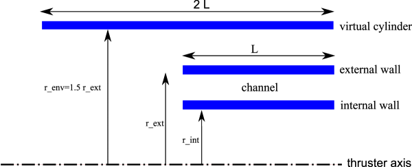
A semi-empirical time-dependent thermal model of a Hall effect thruster has recently been developed in order to determine the energy flux from a measurement of the temporal evolution of the channel wall temperature [16]. Yet, this model can be used the other way, i.e. to determine the wall temperature from the applied power and the channel sizes. Here, a simplified model of the thruster discharge chamber is used. The thermal enclosure is solely composed of the external and the internal cylindrical walls, as can be seen in Fig. 2, meaning that the anode and the rear part of the channel are not taken into account. A virtual cylinder that surrounds the enclosure is used to simulate the channel environment (coils, magnetic core…), as explained in [16]. In this work, only the steady-state wall temperature, i.e. the equilibrium temperature, is of relevance, meaning that the transient regime is ignored. Moreover, our previous studies reveal that, to a great extent, heat conduction through walls can be neglected, only taking radiation heat transfer into account [16]. Under these assumptions, the total energy leaving a grey surface is , where is the Stefan-Boltzmann constant, and the fraction of energy radiated towards another surface can be calculated by multiplying the total radiated energy with the grey body configuration factor [16]. The uniform temperature of the virtual cylinder is assumed to be K. As the temperature of the ceramic thruster walls is much higher, the virtual cylinder can be regarded as a mere heat sink. In order to assess the wall temperature, two quantities are needed: the energy flux as well as the thruster dimensions. The total power transferred to the channel walls was found to be of about 10 % of the input power for various Hall thruster [16]. It was also demonstrated that is almost split in equal amounts among the internal and external walls [16]:
| (3.1) |
Knowing the thruster dimensions , and , the wall
temperature can be computed as a function of the input power.
One must then check that the wall temperature does not exceed
. The validity of this simple thermal model has been put to
the test by comparing the calculated and the measured wall
temperature at a given applied power for several Hall thrusters.
Results obtained with the PPSX000 thruster are displayed in
Table 1. They clearly reveal a good agreement
as the gap stays below 10 %.
With BN-SiO2 walls, a consistent value for is 970 K in compliance with outcomes of a study on the thermal behavior of Hall thrusters performed a few years ago [17]. The maximum authorized input power that corresponds to has been computed for a group of thrusters with different characteristic dimensions using a power loss factor of 10 %. Results are shown in Table 2. Numbers are consistent with the range of operation power of tested thruster but for the micro-Hall and the NASA-built thruster. In the case of the micro-thruster, the computed maximum input power is only W whereas this thruster operates at a power level of W [18]. This is not surprising as the thruster is equipped with a water cooling systems for the channel walls. The estimated maximum input power for the NASA-457M thruster is only of about kW although this thruster is designed to be utilized around kW. Yet, the origin of the discrepancy is well identified. In the thermal model, the power losses due to plasma wall interactions are supposed to be 10 % of the total input power for all thrusters without taking into account a possible size effect. As was shown in a previous work [16], this percentage is a function of the thruster size and it decreases when the size rises. In short, the trend originates from the fact that the ratio of surface ( loss term) to volume ( thrust generation term) decreases with the size. Indeed, when neglecting losses at the channel back, the surface to volume ratio is equal to 1/ for the channel of a HET. As a consequence, the percentage of power losses in the NASA-475M must be below 10 %. The thermal model gives a value of 5 % when the wall temperature is fixed to 970 K.
Naturally, numbers given in Table 2 do not represent an upper limit in input power and a thruster can run at a power higher than the one given by the thermal model, as the BN-SiO2 ceramic can stand a temperatures larger than K. The efficiency as well as the lifetime are nonetheless affected when the channel wall temperature is in excess of 1100 K [20].
4 An empirical approach to the sizing method
4.1 Description of the database
A thorough open literature search using a wide range of resources
combined with data-gathering within the French research program on
electric propulsion allowed us to create a large database on Hall
effect thrusters performances. The database contains information
about thruster geometry as well as performances, notably the thrust
T, the specific impulse and the efficiency
for a series of 23 different single-stage Hall
thrusters. Moreover, the database includes information about the
magnetic field strength B, the discharge channel wall
materials and the propellant gas. The entire database covers a vast
range of input power that stretches from 10 W up to 50 kW and a
large collection of data points in terms of applied discharge
voltage and gas mass flow rate. A broad range of thrust level is
certainly covered, going from 0.4 mN with a micro Hall thruster up
to the 2.95 N delivers by the high-power thruster developed at
NASA. The database also incorporates a few data about anode layer
thrusters (TAL) of which the distinguishing features are
a conducting channel wall and a short channel length [2].
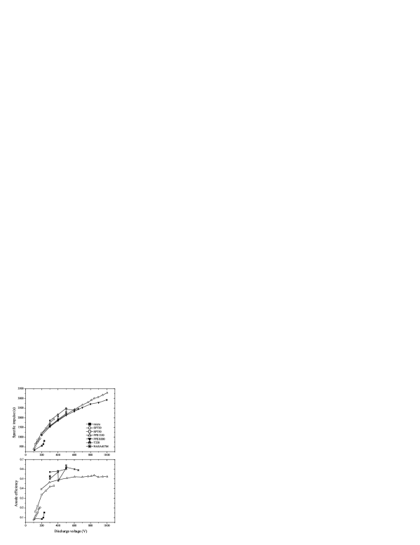
A part of the collected data in terms of performance level is displayed in Fig. 3 and in Fig. 4. For all thrusters, channel walls are made of BN-SiO2 and the propellant gas is xenon. The thrusters used to construct the two figures are the following: a 4 mm in diameter micro-Hall thruster operating at 10-40 W [18], a laboratory model of the low power SPT20 thruster [19], a SPT50 thruster manufactured by the Kurchatov Institute [19], the 1.5 kW-class PPS1350 HET developed and manufactured by Snecma [20], the 5 kW-class PPSX000 thruster which is a laboratory version of the PPS5000 technology demonstrator developed by Snecma [20], the 10 kW T220 designed and built by TRW and Space Power Inc. [21], as well as the 50 kW-class NASA-457M thruster [22]. The development of the thrust as a function of the discharge voltage is shown in Fig. 3 for the seven aforementioned HETs. The thrust of course increases with . When operating at 0.2 mg/s and = 110 V, the micro-thruster delivers 0.4 mN of thrust. On the opposite side of the thrust domain, the high-power NASA-457M thruster furnishes 970 mN of thrust when running at 35.2 mg/s and = 650 V. The evolution of the specific impulse along with the applied voltage is shown in Fig. 4. The increases with and all thrusters follow an identical trend but the micro-thruster. The Snecma-built PPS1350 thruster delivers an above 3250 s when it is fired at 1000 V in a low gas flow regime, as can be seen in Fig. 4. An of 3757 s was achieved by the SPT115 thruster at 1110 V with a gas flow rate of 2.45 mg/s. The behavior of the anode thrust efficiency is shown in Fig. 4. For most thrusters, a maximum is reached around = 600 V when the walls are made of BN-SiO2 ceramic. This specific behavior is likely to originate from the wall material properties combined with a change of the plasma properties at high voltage [20]. The plot in Fig. 4 reveals that the efficiency increases with the thruster size, as discussed in the preceding section.
4.2 Validity of the scaling laws
The propellant conversion efficiency is the ratio of the ion mass flow rate to the propellant mass flow rate:
| (4.1) |
Therefore is not constant, as was considered in section 2.2, but it is a function of the discharge voltage and the mass flow rate. The value of can be obtained from the performance data using the following equation:
| (4.2) |
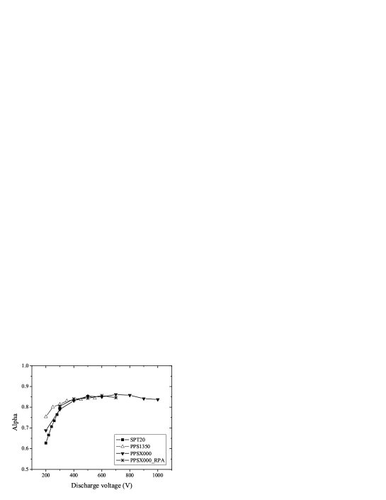
Figure 5 shows the calculated values of for three different thrusters as a function of the applied voltage when only Xe+ ions are taken into account. This figure indicates that depends both on the thruster size and on the value of . The small SPT20 thruster indeed exhibits the lowest values of . There is a natural link between , and the dimensions. As can be seen in Fig. 5, increases quickly with the applied voltage, and for a large thruster it approaches unity at high voltage. The growth of is especially connected with the electron temperature that increases with the voltage [23]. Actually, the production of multiply-charged ions must also be dealt for accurately assessing the value of [24]. The growth of is connected with both the the electron temperature and the fraction of multiply-charged ions [24]. The two quantities increase with the voltage. According to the collected data set, the calculated values of vary between 0.3 and 0.96, not taking into account the micro thruster. For low voltages, drops quickly due to a weak electron temperature. For an input power higher than 1 kW and an applied voltage above 300 V, the quantity is commonly in the range 0.8 - 0.9. The value determined by means of Eq. 4.2 are slightly underestimated as voltage losses are not accounted for. Nevertheless, the value of obtained when using the ion velocity measured by way of a repulsing potential analyzer in the thruster near field are close to the ones computed with as kinetic energy [25]. That means the voltage losses term is small.
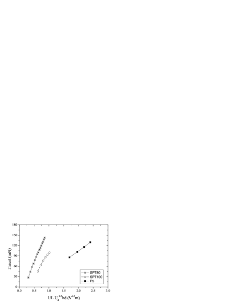
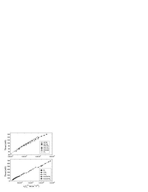
Figure 6 shows the thrust as the function of the product for a large collection of HETs and operating conditions. Apart from SPT20 thruster points at low power, all data points are aligned. As suggested earlier, the coefficient is almost constant. From the slope of the curve in Fig. 6, one finds = (0.890.01). Note that data about the SPT20 thruster are not considered for the linear fit. Equation 2.20 gives a relation between the thrust, the voltage and the characteristic dimensions. In Fig. 7, the thrust is plotted as a function of the product , as established by Eq. 2.20, for a variety of Hall thrusters firing with mg/s. The normal operating point of the thrusters ranges from 500 W to 5 kW. As can be seen, curves are linear, however, the slope depends upon the input power. A detailed analysis carried out with all thrusters available in the database reveals that thrusters group together depending on their normal operating power. Equation 2.20 was derived using the relation between and the dimensions as well as the series of assumptions listed at the beginning of section 2.1. Though graph of Fig. 7 indicates that some of the assumptions may be too limiting. First, the propellant gas temperature is said to be constant an independent of in such a way that the propellant speed inside the channel is fixed and it does not vary with . In effect the gas temperature depends on the thruster geometry as well as on the input power. Second, the propellant conversion efficiency , which was assumed to be constant, is a function of the discharge voltage as demonstrated hereinbefore. These two points are confirmed by the fact that the curves for thrusters of about the same sizes, e.g. the P5 and the PPSX000 as well as the PPS1350 and the SPT100, are close to each others. Yet, when the thrust is plotted as a function of the product , all datapoints are aligned, as can be observed in Fig. 8. The plot is independent of the power level and the thruster sizes. This experimental fact reveals that the Melikov-Morozov criterion does not implies that the ratio is identical for all thrusters, whatever the geometry and design. It is even the opposite, and the mean value of the parameter given in Table 3 must seen as the typical value that warrants a fine thruster functioning.
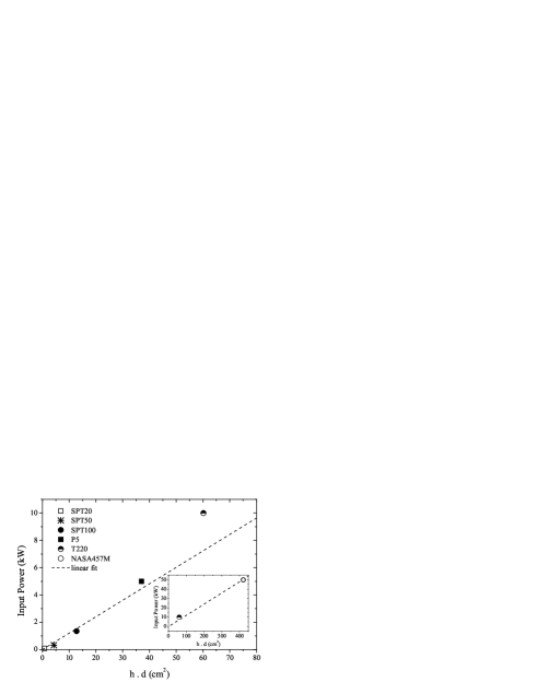
As explained in section 2.1, the input power naturally depends upon the characteristic thruster dimensions. Assuming , is found to be a function of the ratio , see Eq. 2.21. However, using all gathered data, it appears that varies linearly with the product, as shown in Fig. 9. This linear relation will be used in the remainder of the paper when sizing high-power Hall thrusters.
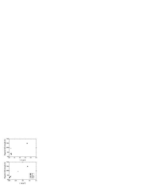
At the end of section 2.1, two scaling laws have been established for the magnetic field , see Eq. 2.13 and 2.15. The two plots in Fig. 10 show the evolution of with and , respectively, for five different Hall effect thrusters. As can be seen, data points are well aligned only when the product is considered. Therefore, one can consider that the scaling laws is more suitable than the one that solely incorporates the channel length , although it was never considered up until then.
Finally, a last remark is worth making. The atom density that warrants an efficient functioning of a Hall effect thruster can be inferred from the xenon mass flow rate when the thruster dimensions are known, see Eq. 2.7. Assuming a propellant temperature of 800 K inside the channel and taking the gas mass flow rate at normal operating conditions, one finds m-3 whatever the thruster picked in the database, but the micro-thruster. This number, which can be envisaged as an atom density constraint, is in good agreement with the value commonly found in literature.
4.3 Determination of the proportionality coefficients
In order to assess the required thruster dimensions by way of a scaling method for an available input power and a given thrust level, it is necessary to know the proportionality coefficients of equations encountered in section 2.2. As it was previously shown, the specific impulse is proportional to :
| (4.3) |
This coefficient can also be inferred from the experimental curve as a function of , see Fig. 4. The mean value of the coefficient determined by using the database is .
The thrust is described by the following equation:
| (4.4) |
when using . The coefficient is the slope of the curve T versus , see Fig. 6. Using the experimental dataset, one obtains . A second relation was established for the thrust:
| (4.5) |
Assuming that the electron temperature is 10 eV and the gas temperature is 800 K, the corresponding velocities are m/s and m/s, respectively. Furthermore, is taken to be and is equal to . Using those numbers, one finds . The value of the coefficient can be determined using our database as the size is known for all thrusters. With numbers given above, one finds = 0.007, and it comes . The true experimental value is obtained by way of the type of curves plotted in Fig. 7, notwithstanding the fact that the slope of relation 2.20 depends upon the thruster normal operating power as discussed previously. A mean value is =0.0924.
As shown in Fig. 9, the input power is a function of the product under our assumptions, and one can write:
| (4.6) |
The value of is calculated from the collection of operating points selecting various thrusters to vary the product. The empirical value of the proportionality coefficient is taken to be the slope of the line in Fig. 9: . The value of all coefficients are summarized in Table 3. Finally, the thruster dimensions can be assessed afterwards, as it will be shown in the next section.
5 Design of a high power Hall Effect Thruster
High-power Hall effect thrusters in the range 10 - 30 kW and able to deliver a thrust level around 1 N with a specific impulse of about 2500 s are thought to be used as the primary propulsion system for robotic space probes during interplanetary journeys [1, 26, 27]. Such high-power Hall thrusters may also be of interest for orbit transfer maneuvers of large satellites. Only a few high-power prototypes have been developed in the world so far and a significant research effort on this specific technology is now appearing within Europe. For these reasons, the sizing method based on aforementioned widely applicable scaling laws in combination with our large database is employed to design a 20 kW-class thruster with N as well as a 25 kW-class Hall thruster with N.
The discharge voltage of the two thrusters is fixed to V, i.e. = 2760 s when considering singly-charged ions and no voltage losses. Xenon is used as a propellant gas. The channel walls are assumed to be made of BN-SiO2 ceramics. The highest wall temperature is set to 970 K. In this study, losses are fixed to 6 % of the applied power. The parameters and are set to 0.9 and 0.007, respectively, in agreement with previous analysis.
5.1 Sizing of a 20 kW-class thruster
The process that consists in determining the thruster characteristic dimensions , and as well as the magnetic field must be carried out step by step.
-
1.
The required mass flow rate is determined by means of Eq. 4.4.
-
2.
The product is found using the relationship 4.6.
-
3.
The channel length is given by Eq 4.5.
-
4.
The thermal constraint is used to assess the value of both the channel width and the average channel diameter . The process can be iterative, in the case the dimensions must be changed in order to satisfy the constraint: wall temperature below .
-
5.
The magnetic field strength is then obtained from the relation , see Fig. 10.
-
6.
At last, it should be verified that the number density is close to , as explained at the end of section 4.2.
The channel length is the dimension that is the most difficult to
determine as the proportionality coefficient strongly
depends on the value of . In fact, the ratio between
and is not constant but it can vary considerably for
different mass flow rates, voltages and thruster types. Since the
value of the product given by the method is quite reliable, it
appears better to modify rather the channel length than the mean
diameter in case an iterative loop is necessary to satisfy the
thermal constraint. Indeed, outcomes of the thermal model are not
much influenced by a change in the value of as losses are
fixed.
For the 20 kW Hall thruster (1 N, 500 V), the sizing method leads to: mg/s, mm, mm and mm and a magnetic field strength G. The temperature is K and K for the external, respectively the internal, dielectric channel wall. Finally, the value m-3 is found for the atom number density.
5.2 Sizing of a 25 kW-class thruster
The same approach was applied to design a 25 kW Hall thruster (1.5 N, 500 V). The sizing method gives: mg/s, mm, mm and mm. The magnetic field strength is equal to 135 G. The temperature is K and K for the external, respectively the internal, dielectric channel wall. The calculated number density is m-3.
The outcomes of our sizing method can be compared with results obtained in a study by M. Andrenucci and co-workers in which sizes are fixed instead of being computed [9]. They used their specific approach to design a 25 kW Hall thruster operating at 275 V. The dimensions are fixed to mm, mm and mm. They found a xenon mass flow rate of 88.7 mg/s, a thrust level of 1.49 N and a magnetic field of 135 G. Our procedure leads to a mass flow rate of 83.4 mg/s, an atom density of m-3 and the same magnitude for . Moreover, their thruster dimensions do not permit to respect our thermal constraint as K and K. Nevertheless, to achieve a thrust level of 1.49 N with = 275 V, our approach predicts mm, mm and mm, values that are not too far from the ones chosen a priori referring to a vast database [9].
6 Conclusion
The Hall effect thruster sizing method described in these works considers the three characteristic thruster dimensions , and , as well as the magnetic field strength . The method relies on analytical laws that are established from the fundamental principles that govern the physics of a Hall thruster in the frame of simplifying assumptions. Besides, the thruster geometry must fulfill criteria about channel wall temperature and atomic number density. A vast database that incorporates 23 single-stage Hall thrusters covering a power range between 10 W and 50 kW allows to check the validity of scaling laws and to find the value of corresponding coefficients necessary to proportion a thruster. The sizing approach was then employed to obtain a proper estimate of characteristic dimensions and magnetic field strength for a 20 kW and a 25 kW Hall thruster capable of providing a thrust level of 1 N, respectively 1.5 N. Our approach gave also satisfactory results when it was applied to check the design of a 100 W Hall thruster currently under development and test in our laboratory.
Scaling laws developed here solely represent a first order approach due to the numerous simplifying assumptions on the physics at work in a Hall thruster. Nevertheless, for a given set of operating conditions they furnish a first estimate of the geometry and the magnetic field strength of a thruster, which permits to save time during the design and optimization stages. One way to improve the accuracy of the scaling method is to reduce the number of assumptions. The evolution of the electron temperature, of the gas temperature and of the fraction of multiply-charged ion species as a function of the discharge voltage could for instance be taken into account, however, available data are scarce that anyway limits the gain. Another way could consist in applying a statistical analysis of the vast database to directly obtain empirical sizing formulas. The design of experiment method could be an appropriate tool to achieve that goal. Finally, attempt to incorporate the magnetic field topology into scaling laws would represent a tremendous progress as the latter is the most fundamental feature to ensure a successful operation.
Acknowledgments
This work is carried out in the frame of the CNRS/CNES/SNECMA/Universités joint research program 3161 entitled “Propulsion par plasma dans l’espace”.
References
- [1] R.H. Frisbee, Advanced space propulsion for the 21st century, J. Propulsion Power 19, 1129, 2003
- [2] V.V. Zhurin, H.R. Kaufmann, R.S. Robinson, Physics of closed drift thrusters, Plasma Sources Sci. Technol. 8, R1, 1999
- [3] N. Gascon, M. Dudeck, S. Barral, Wall material effects in stationary plasma thrusters I. Parametric studies of an SPT-100, Phys. Plasmas 10, 4123, 2003
- [4] C.R. Koppel, F. Marchandise, M. Prioul, D. Estublier, F. Darnon, The SMART-1 electric propulsion subsystem around the Moon: In flight experience, Proceedings of the 41th Joint Propulsion Conference, Tucson, Arizona, AIAA paper 05-3671, 2005
- [5] A.I. Morozov and V.V. Savelyev, Fundamentals of stationary plasma thruster theory, Reviews of Plasma Physics 21 (edited by B.B. Kadomtsev and V.D. Shafranov) Consultant Bureau, New York, 2000
- [6] V. Kim, Main physical features and processes determining the performance of stationary plasma thrusters J. Propul. Power 14, 736, 1998
- [7] J. Ashkenazy, Y. Raitses, G. Appelbaum, Low power scaling of Hall thrusters, Proceedings of the 2nd European Spacecraft Propulsion Conference, Noordwijk, The Netherlands, ESA Publications Division, 1997
- [8] V. Khayms, M. Martinez-Sanchez, Design of miniaturized Hall thruster for microsatellites, Proceedings of the 32nd Joint Propulsion Conference, Lake Buena Vista, AIAA paper 96-3291, 1996
- [9] T. Misuri, F. Battista, C. Barbieri, E.A. De Marco, M. Andrenucci, High power Hall thruster design options, Proceedings of the 30th International Electric Propulsion Conference, Florence, Italy, IEPC paper 07-311, 2007
- [10] Y. Daren, D. Yongjie, Z. Zhi. Improvement on the scaling theory of the stationary plasma thruser, J. Propulsion Power 14, 139 2005
- [11] V. Kim, V. Kozlov, A. Skrylnikov et al., Development and investigation of the SPT-20 and SPT-25 laboratory models, Proceedings of the 1st Annual International Conference and Exhibition. Small Satellites: New technologies, achievements, problems and prospects for the International co-operation in the new millenium, section YIII ”Jet Propulion”, Moscow, 2000
- [12] J.W. Koo, I.D. Boyd, Modelling of anomalous electron mobility in Hall thrusters, Phys. Plasmas 13, 033501, 2006 and references herein.
- [13] A. Gallimore, Near- and far-field characterization of Stationary plasma thruster plumes, J. Spacecraft Rockets 38, 441, 2001
- [14] J.D. Huba, NRL Plasma Formulary, Naval Research Laboratory, Washington, 2007
- [15] M. A. Lieberman, A. J. Lichtenberg, Principles of plasma discharges and materials processing, John Wiley & Sons, Inc., New York, 1994
- [16] S. Mazouffre, K. Dannenmayer, J. Pérez-Luna, Examination of plasma-wall interactions in Hall effect thruster by means of calibrated thermal imaging, J. Appl. Phys. 102, 23304, 2007
- [17] S. Mazouffre, P. Echegut, M. Dudeck, A calibrated infrared imaging study on the steady state thermal behavior of Hall effect thrusters, Plasma Sources Sci. Technol. 15, 13, 2006
- [18] T. Ito, N. Gascon, W.S. Crawford, M.A. Cappelli, Experimental characterization of a micro-Hall thruster, J. Propul. Power, 23, 5, 2007
- [19] G. Guerrini, C. Michaut, M. Dudeck, M. Bacal, Parameter analysis of three small ion thrusters, Proceedings of the 2nd European Spacecraft Propulsion Conference, Noordwijk, The Netherlands, ESA Publications Division, 1997
- [20] S. Mazouffre, A. Lazurenko, P. Lasgorceix, M. Dudeck, S. d’Escrivan, O. Duchemin, Expanding frontiers: Towards high power Hall effect thrusters for interplanetary jouneys, Proceedings of the 7th International Symposium on Launcher Technologies, Paper O-25, 2007
- [21] R.S. Jankovsky, C. McLean, J. McVey, Preliminary evaluation of a 10kW Hall thruster, Proceedings of the 37th AIAA Aerospace Science Meeting and Exhibit, Reno, Nevada, AIAA paper 99-0456, 1999
- [22] D.H. Manzella, R.S. Jankovsky, R.R. Hofer, Laboratory model 50kW Hall thruster, Proceedings of the 39th Joint Propulsion Conference, Indianapolis, Indiana, AIAA paper 02-3676, 2002
- [23] Y. Raitses, D. Staack, M. Keidar, N.J. Fisch, Electron-wall interaction in Hall thrusters, Phys. Plasmas 12, 057104, 2005
- [24] A. Lazurenko, V. Vial, A. Bouchoule, A. Skrylnikov, V. Kozlov, V. Kim, Dual-mode operation of stationary plasma thrusters, J. Propul. Power 22, 38, 2006.
- [25] S. Mazouffre, V. Kulaev, Ion diagnostics of a discharge in crossed electric and magnetic fields for electric propulsion, submitted to Plasma Sources Sci. Technol., 2009
- [26] K.E. Witzberger, D. Manzella, Performances of solar electric powered deep space missions using Hall thruster propulsion, Proceedings of the 41st Joint Propulsion Conference, Tucson, Arizona, AIAA paper 05-4268, 2005
- [27] L. Johnson, R. A. Meyer, K. Frame, In-space propulsion technologies for robotic exploration of the solar system, Proceedings of the 42nd Joint Propulsion Conference, Sacramento, CA, AIAA paper 06-4687,2006
| Power (W) | (K) | (K) | ||
|---|---|---|---|---|
| Mes. | Calc. | Mes. | Calc. | |
| 1605 | 690 | 655 | 740 | 710 |
| 2460 | 762 | 729 | 788 | 790 |
| 4620 | 833 | 854 | 862 | 926 |
| Thruster | Maximum input |
|---|---|
| power (W) | |
| micro | 9 |
| SPT20 | 210 |
| SPT50 | 870 |
| PPS1350 | 2060 |
| SPT100 | 2080 |
| PPSX000 | 4200 |
| P5 | 5550 |
| NASA-457M | 20300 |
| Coefficient | Value |
|---|---|
| 123.4 | |
| 99.7 | |
| 1090.8 | |
| 1077.3 | |
| 0.109 | |
| 0.092 | |
| 0.007 |