D.B. is now with ] Scuola Normale Superiore di Pisa, NEST Piazza dei Cavalieri 7, 56126 Pisa, Italy.
Coherent Rabi response of a charge-phase qubit under microwave irradiation
Abstract
We report on radio-frequency measurements of the charge-phase qubit being under continuous microwave irradiation in the state of weak coupling to a radio-frequency tank circuit. We studied the rf impedance dependence on the two important parameters such as power of microwave irradiation whose frequency is close to the gap between the two lowest qubit energy levels, and temperature of the internal heat bath. We have found that backaction effects of the qubit on the rf tank, and vice versa, tank on the qubit, lead to a negative as well as a positive real part of the qubit impedance Re seen by the tank. We have implemented noise spectroscopy measurements for direct impedance readout at the extreme points corresponding to maximum voltage response and obtained absolute values of about for the negative and positive Re. Our results demonstrate the existence and persistence of the coherent single- and multi-photon Rabi dynamics of the qubit with both negative and positive dynamic resistance inserted into the tank in the temperature range of 10 to 200 mK.
pacs:
03.75.Lm, 74.50.+r, 85.25.CpI Introduction
Nowadays the problem is under intensive discussion of building a new class of information signal detectors based on solid-state Josephson qubits in which coherent phenomena like single- and multi-photon Rabi oscillations occur. R1 ; R2 ; R3 ; R4 ; R5 ; R6 ; R7 The behavior of these detectors would essentially differ from that of quantum devices utilizing non-linear effects of macroscopic quantum tunnelling, macroscopic resonant tunnelling and superposition of macroscopic states by the presence of intrinsic generation at the Rabi frequency. The variation of ground and excited levels population with the Rabi frequency results in a periodic alteration of the magnitude and sign of reactive parameter of the detector. Similar to the known classical electrodynamics of Josephson junction in a resonator,Kanter ; Likharev the interaction of a weak signal from the tank circuit with Rabi oscillations may lead to synchronization effects and emerging the negative resistance, i.e. the signal amplification.Smirnov1 ; Krech1 ; Greenberg The amplitude of these effects will depend on the qubit decoherence time (Rabi oscillations frequency band), the latter must exceed the period of oscillations in the tank circuit coupled with the qubit, where is the tank circuit resonant frequency.
It was shownSisyphus1 ; Sisyphus2 that a qubit placed in microwave field might show Sisyphus cooling effectsSisyphus2 ; FQ ; FQ1&2 for the opposite limit , i.e. when the qubit decoherence time was less than the tank circuit oscillation period which was about the relaxation time . The observation of the negative resistance inserted by the qubit into the tank circuit is possible in both cases. However, the resistance value and its dependence on temperature, frequency and microwave power will substantially differ. In both cases, the characteristics of the qubit-detector system will depend on the qubit’s effective temperature , which is contributed by the measurement process itself, the physical temperature of the bath , the quality of thermalizationtherm of the qubit input circuit (gates), etc. Note that, in a region of large values, the observation of complicated classical electrodynamics is possible associated with so called pseudo-Rabi oscillations.P-Rabi
The aim of this work is to experimentally analyze coherent processes in a charge-phase qubitZorin ; Krech2 being under continuous microwave irradiation in the state of weak coupling to a radio-frequency tank circuit. It is important to note here that our experiment is similar but not identical to that of Ref. Sisyphus2, . In this paper we address the problem of the coherent single- and multi-photon Rabi dynamics of the charge-phase qubit with in a wide temperature range. The direct observation of absorption and irradiation properties of a strongly driven qubit coupled to a rf tank circuit, being of fundamental interest, also has potential applications for quantum detectors based on charge-flux qubits with self-Rabi frequency pumping.
The paper is organized as follows. In Sec. II theoretical description of a strongly driven charge-phase qubit coupled to an rf tank-detector and analysis of measured output functions are given. The main Sec. III is devoted to detailed experimental investigation of coherent single- and multi-photon Rabi dynamics of the strongly driven charge-phase qubit probed by rf tank detector.
II System of charge-phase qubit and tank circuit
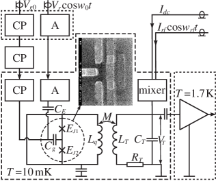
The charge-phase qubit (Fig. 1) is topologically a single-contact rf SQUID whose Josephson junction is replaced by a single-Cooper-pair transistor.Zorin ; Krech2 ; Friedman ; Zorin2 The latter consists of two mesoscopic junctions with Josephson energies and capacitances , coupled by a small island. The Hamiltonian of the charge-phase qubit in the eigenstate basis within the two-level approximation () and the small-inductance limit reads as R2 ; Zorin ; Krech2
| (1) |
where the effective Josephson energy is a function of the total phase bias across both junctions ( and are phase differences at the individual junctions); , parameter characterizes the polarization charge in the island controlled by the gate voltage via the charge gate capacitance , and is the two-electron Coulomb energy of the island expressed through its total capacitance regarding the rest of the system. The inductance of the qubit loop is assumed to conform to the small-inductance limit (typically , is the flux quantum), so that the total flux through the qubit loop , and the potential (Josephson) energy of the qubit is periodic on . Thus, the charge-phase qubit design permits the implementation of an in-situ control of Josephson coupling energy by means of external magnetic flux and the effective charging energy by gate voltage . The current operator of an isolated qubit corresponding to the Hamiltonian (1) is given by
| (2) |
so that its basis states are discriminated by the two oppositely circulating in the qubit loop supercurrents that correspond to the ground and the excited qubit energy levels.
In general case, at arbitrary ratio of the Josephson and charging energies (while the two-level approximation (1) is determined by ) the energy spectrum and eigenfunctions of the charge-phase qubit are given, respectively, by the Bloch bands and the Bloch wave functions ( is the band index and the quasicharge) that are numerical solutions of Schrödinger equation with Hamiltonian containing all the charge states and periodic Josephson potential. Zorin ; Zorin2 Then the lowest two energy levels form the basis of the charge-phase qubit, so that .
In our experiments the qubit is driven by coupling microwave field of frequency and amplitude to the voltage gate with constant voltage component , , and its dynamical properties are probed by the well-known rf SQUID impedance measuring techniqueIMT1 ; IMT2 (IMT) following the conception of weak continuous quantum measurements.Smirnov1 ; Korotkov ; Averin1 ; Il'ichev ; Sillanpaa In the IMT the qubit is inductively coupled to a high-quality tank circuit serving as a linear detector. For the tank circuit driven by a small amplitude external rf-bias current the measured output functions are the amplitude of the voltage oscillations and the voltage-current phase shift . Also, the spectrum of voltage fluctuations in the undriven tank can be sensitive to qubit dynamics (the noise spectroscopy method).
The IMT weak continuous measurements were effectively used for microwave spectroscopy and characterization of charge-phase qubits.CH ; CH1 There the resonant response of the qubit to microwave irradiation was observed through a change of the average qubit Josephson inductance making contribution to the reactive part of the tank impedance. Essentially different effects were predicted in Ref. Smirnov1, , when at resonant microwave irradiation there exist coherent low-frequency (Rabi) oscillations in a qubit with frequency nearby the tank resonant frequency. Then damping and amplification of the voltage signal , with respective modification of the spectrum of voltage fluctuations in the undriven tank and its quality factor, should be observed owing to insertion of the positive or negative dynamic active impedance (resistance) into the tank circuit from a qubit. These phenomena enable probing the coherent properties of qubits necessary for quantum manipulations.
In the presence of the qubit, at resonant condition of driving the tank, the expressions for its effective damping rate , the resonant frequency , the amplitude of the voltage oscillations and the voltage-current phase shift have the form Smirnov1 ; Krech1
| (3a) | |||
| (3b) | |||
| (3c) | |||
| (3d) | |||
where is the own damping rate of the tank, is the coupling coefficient, is the mutual qubit-tank inductance, and are the inductance and capacitance of the tank respectively, and are the real and imaginary parts of the qubit magnetic susceptibility . The latter is defined by the relation and describes low-frequency response of a qubit to a tank probing signal. The rate of absorbtion of weak signal energy by a qubit from a tank ( is current in the tank), according to properties of generalized susceptibility.LLP That is the function defines the absorption () and irradiation () properties of a driven qubit coupled to rf tank-detector.
Renormalization (3a), (3b) of the tank parameters at resonance () involves renormalization of the tank quality factor
| (4) |
where is the effective inductance of the tank including inserted from the qubit inductance , and is the effective resistance of the tank including inserted from the qubit resistance [, where is qubit impedance seen by the tank]. The characteristic impedance of the tank at resonance
so that the tank voltage is inversely proportional to the effective tank resistance . The Lorentzian-shaped voltage fluctuations spectrum in the tank is characterized by the renormalized quality factor (4).
For the special case of charge-phase qubits, the theory of Rabi oscillations and low-frequency qubit response have been investigated in Ref. Krech1, . The Rabi frequency of coherent low-frequency oscillations generated at near-resonant driving of the charge-phase qubit by microwave field reads asKrech1
| (5) |
where is the core -photon Rabi frequency, . The most essential in our context low-frequency parts of the functions in the presence of Rabi oscillations have the formKrech1
| (6) |
where denotes the dephasing rate for the transverse component of the Bloch vector to determine the qubit dynamics, the polarization constant , being the probability of the qubit excited state ( the reduced density matrix of the qubit), at that . It is essential that the parameter , and therefore and the qubit-induced contribution to the effective damping rate of tank , (3a), alter their sign when the detuning parameter does so. Thus the effective resistance contains a negative contribution from the qubit at (, ) and a positive contribution at (, ).
As seen from (6), the functions have non-monotonous resonant character near -photon Rabi frequencies. In their turn, as follows from (3), the weak continuous quantum measurement output functions of the tank-detector expressed through have resonant contributions, conditioned by coherent Rabi dynamics of the qubit at with small damping and decoherence rates, . Notice that in previous spectroscopy experiments with charge-phase qubitsCH ; CH1 there was only small changing of the tank effective resistance ( and ) and the voltage conditioned by could only decrease, as seen from (3c). In case of coherent Rabi dynamics at , can be nonzero while , and the voltage can both decrease or increase relative to the voltage level of the passive tank depending on sign of .
Recently, quantum theory of the low-frequency linear susceptibility of flux and charge-phase qubits subjected to microwave irradiation was developed within the density matrix formalism in Ref. Greenberg, . This theory as well describes parametric effects of reduction and amplification of signal and quality of the tank coupled to charge-phase qubits in the strong charge limit .
The above theoretical outline gives only a qualitative picture of the effects in the system of charge-phase qubit and tank-detector and cannot afford for their quantitative description. Firstly, the charge-phase qubit has such parameters that in our experiment, while its Hamiltonian and the energy spectrum are of more complicated structure as compared to the two-level approximation (1), and numerical solving the Schrödinger equation is needed for this structure to be found. Another important feature is a strong nonlinearity of the qubit’s response to external electromagnetic excitation due to Josephson character of the energy potential for the quantum coordinate of the system. As shown in the quantum-mechanical model of a SQUID ring coupled to an electromagnetic field,Everitt the energy levels of the SQUID with coherent dynamics of magnetic flux when excited by strong electromagnetic field change so dramatically in time that their time averages essentially differ from the initial system levels. The shape of the time-averaged energy levels in the high-power electromagnetic field depends on its frequency and amplitude in a complicated manner showing compression between the levels and the interference patterns of resonant interactions between the two lowest ones. Similar by their nature effects are observed in nonlinear quantum optics. So, a two-level atom in strong electromagnetic field demonstrates nonlinear effects of compression its energy (quasi)levels and Stark effect.Krainov Another basic aspect of the theoretical consideration of quantum dynamics of the qubit-detector system is taking into account the temperature effect resulting in finite width of the signal generation band in the qubit and in the tank, thus determining eventually the shape of the observed signal characteristics.
III Charge-phase qubit and experimental results
III.1 Qubit calibration
The sample (see Fig. 1) was fabricated by electron beam lithography and conventional two-angle technology of aluminum thin film deposition to create two mesoscopic Josephson junctions with area nm2, tunnel resistance and GHz. The evaluation of was obtained from direct measurements of the tunnel resistance of a large-area ”witness”. Analysis of the scanning electron micrograph of the sample shows that the areas of the Josephson junctions in this charge-phase sample differ by appr. . The difference between the contacts areas determines the asymmetry of the critical currents and leads to the optical evaluation of minimal value of the effective Josephson energy of the Cooper-pair transistor. The two-electron Coulomb energy evaluated on the basis of the geometric transistor capacitance is . Real value of may be somewhat smaller due to effect of the stray capacitance of the island. Thus, the two characteristic energies in the given qubit are of the same order of magnitude and meet the adiabaticity condition .
Choosing instead of strong condition we decrease the influence of nonequilibrium noise of the charge on coherent dynamics of the qubit.R2 With the same aid,Zorin2 ; Makhlin both the ratio and the ratio of the real part of the charge-gate line impedance to the quantum resistance , where , are made small in the given sample of charge-phase qubit. To reduce the qubit effective temperature , all the input electric circuits were thoroughly filtered by multiresonance (Cu)O powder filters, and the voltage supply resistor along with the last stage of the copper filter of the charge-gate line were placed onto mK refrigerator stage for better thermalization.
The island volume permits one making an estimation of the number of states and the characteristic temperatureTuominen mK above which the number of the quasiparticle excitations in the island abruptly rises from zero.
The charge-phase qubit Hamiltonian (1) is sensitive to any changes in magnetic flux coupled to the superconducting loop. To minimize the external flux noise, the qubit superconducting loop is implemented as a 1st order gradiometer with minimum distance between the coils. The achieved balancing accuracy (difference between the areas of the gradiometer coils) is of the order of one part in .
To read the change in the amplitude and phase of the oscillations, the tank circuit was linked to a preamplifier placed on K-pot and room temperature electronics. It should be emphasized that the part of the tank circuit kept at temperature K (K-pot) (see Fig. 1) is a source of high-frequency photons that can affect the qubit. Moreover, in addition to amplifying the in-band Rabi-signal, it is obvious that preamplifier can also irradiate at extremely high frequencies thus increasing the effective temperature of the qubit. The qubit decoherence due to back-action from both the tank circuit and the preamplifier depends on many parameters and was not analyzed yet in detail. We will return to this problem below. To reduce , the coupling coefficient was decreased to that led to the parameter . However, coupling to the tank circuit cannot be made arbitrarily small in Rabi qubit-based detectors for the purpose of reducing decoherence and should be optimized. We have found that is close to the most optimal value that provides maximum (Rabi)signal-to-noise ratio due to effect of the high-frequency photons from the measuring circuit. This value substantially differs from the usual match condition for classic rf SQUIDs.Likharev ; IMT1 ; IMT2 Despite the main part of the tank circuit is placed at mK, its effective noise temperature mK in our experiments. It can be shownSmirnov1 ; Zorin2 that at the tank with impedance k at mutual inductance nH in the band kHz contributes sufficiently small noise flux to the qubit outside the region of exact resonance.
The previous measurements displayed that superfluous noises from the microwave line at galvanic coupling with a qubit were unavoidable. Therefore all experimental results were obtained with the qubit placed in a Pb resonator in the region of maximum electric field. The qubit was then continuously irradiated with a microwave field to introduce an alternating voltage component . So, the capacitance formally galvanicly coupled to the charge gate capacitance in Fig. 1 denotes, in fact, coupling of the qubit charge gate to a microwave field. Since the distribution of the electric field only approximately corresponds to that expected for an ideal resonator, we made preliminary measurements of the qubit response to the microwave field as a function of its frequency in the range of 6.6 to 8.0 GHz.
The detailed analysis of the qubit dynamics has shown that extremal positive (peak) and negative (dip) responses to low-amplitude microwave field was observed at frequency GHz, with small deviations and from the point . Assuming that the single-photon process of the higher-level excitation occurs at frequency GHz, we find the effective Josephson energy GHz.
III.2 Single-photon Rabi response
Assumed that one should observe resonant parametric response of the qubit in the region of Rabi frequencies when the microwave field frequency was near that of single-photon transitions, we investigated in detail dependencies and at various amplitudes (powers) of the microwave field. Typical measurement results at GHz are shown in Figs. 2a,b. It is clearly seen from these curves that the single-photon resonant response predicted by (3) – (6) and smeared out by temperature noise and coupling to the readout device is observed at an optimal microwave power. The decrease, as well as increase, of the microwave power compared to its optimal value results in falling of the resonant response amplitude that is explained by the rise of the detuning .
The variations in these experiments are measured simultaneously and, since the rf generator frequency is chosen from the condition , then the technique sensitivity is maximal to the change in the oscillations phase. On the contrary, sensitivity of the voltage channel to small changes of the resonant frequency of the tank near is minimal. Notice the two-photon resonant response seen fairly well in curves in the vicinity of (Fig. 2a) whereas having signal-to-noise ratio at characteristics. The decrease of the amplitude of the two-photon resonant response relative to the single-photon one in Fig. 2a agrees with the theorySmirnov1 that predicts the longest decoherence time in the point of symmetry .
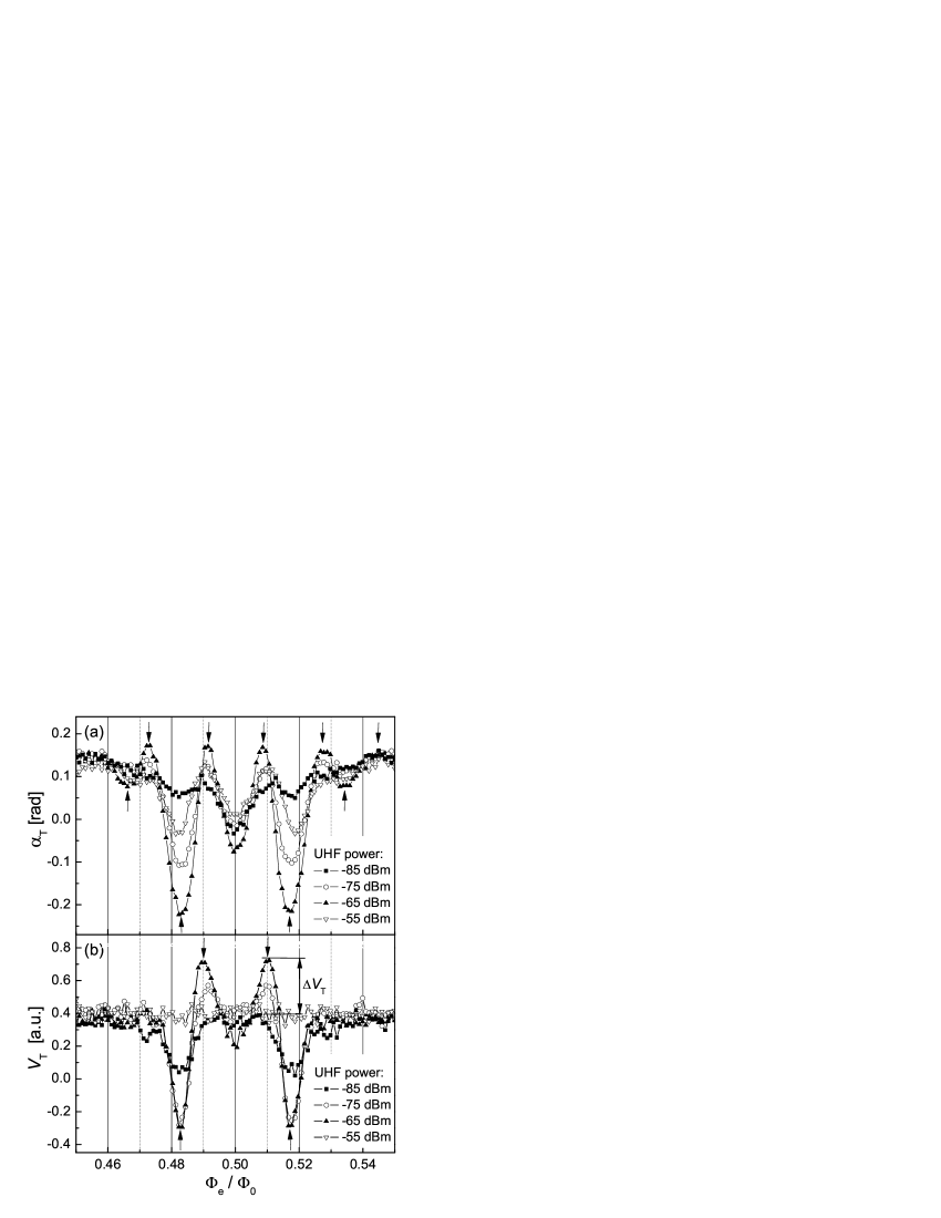
In general case, variations of the phase as well as the amplitude of the parametric oscillations in the tank circuit are bound to the change of its resonance frequency and quality. Thus, presented in Fig. 2a,b dependencies , qualitatively confirm existence of the low-frequency part of the charge-phase qubit susceptibility functions (6) as the Rabi frequency of the qubit passes through the resonant frequency of the tank. Let us consider the evolution of the signals in vicinity of the point . As it follows from the expressions (3), Rabi-response of the qubit in the point should vanish to zero proportionally to the square of the circulating current . At low amplitudes of the microwave field the responses are really small as it is seen from Fig. 2b. However, at power dBm noticeable shifts (as well as ) are observed that points out to appearance of circulating current in the point in the expense of deviation of time-averaged eigenenergies from stationary eigenenergies.Everitt

We use the noise spectroscopy method for the direct impedance measurements. In this case the generator current , and the tank circuit is excited by thermodynamic fluctuations while its characteristics depend on the impedance inserted from the qubit under continuous irradiation. Fig. 3 displays the noise spectral density as a function of frequency for the two extreme (”peak” and ”dip”) points denoted by arrows in Fig. 2b and at the degeneracy point . It is seen from these amplitude-frequency characteristics measured at minimal influence of the tank circuit on the qubit that Rabi oscillations result in visible change of the tank quality and shift of the tank resonant frequency in the ”peak” and ”dip” -points (curves 1 and 2 in Fig. 3, respectively). The sign of the inserted from the qubit Rabi-impedance is determined by the sign of the detuning between energy gap and microwave field frequency . From the quality factor values and the resonant frequencies in the extreme points indicated in Fig. 3 and using (4), we will obtain that the maximum value of the negative resistance inserted into the tank practically coincides with the maximum positive resistance by absolute magnitude while the alteration of its sign implies the transition from the irradiation to the absorption properties of the qubit. The inductance contributions in these points are small () and are also of opposite signs. Note that similar electrodynamics is typical for the parametric interaction of a resonator microwave signal with Josephson oscillations.Kanter In this classic analogue, the maximum amplitude of the parametric effect is determined by fluctuations of the average contact voltage that lead to broadening of the Josephson generation band. So, assuming that the rise of the qubit temperature in the considered case of Rabi oscillations will result in broadening of their spectrum, one should expect some decrease in amplitude of the inserted negative impedance with increasing the bath temperature.
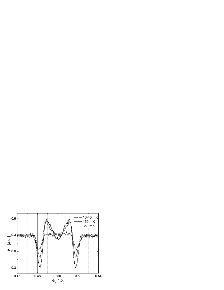
The analysis of temperature dependencies demonstrates that the amplitude of the inserted resistances within experimental accuracy does not depend on in the interval 10 – 40 mK. The amplitude of the inserted impedance decreased by at mK and the extrema in curves smooth out in the interval 60 – 100 mK . The increase of the bath temperature up to 150 – 200 mK leads to the dramatic fall of the amplitude . Note that the calculated temperature mK, at which abrupt decay of the coherent effects is expected, is close to the experimental data. The coherence degradation at is accompanied by fast shortening of the decoherence time and widening of the Rabi oscillation band. Further temperature rise up to 300 – 350 mK causes Rabi-impedance of the qubit seen by the tank vanishing to zero () within the noise level, i.e. the coherent Rabi effects disappear.
The minimal effective temperature of the qubit estimated to be mK is determined mainly by the effect of the readout circuit (tank-detector and HEMT amplifier) and leads to sufficiently large uncertainty in the magnetic flux for the qubit under consideration. Anyway, the dependence Re on the microwave power and the temperature indicates the presence of coherent quantum oscillations at low temperatures that have potential applications as a self-Rabi pumping signal in quantum information detectors.
It is seen from the results presented in Fig. 4 that at the bath temperature 350 mK near the ”dips” are yet observed and associated with the processes of noncoherent quantum tunneling of Cooper pairs, without forming a superposition of the charge states. Therefore, the contribution of the coherent oscillations in the given temperature interval is described as the difference between the values of obtained at 10 and 350 mK. Taking into account that, at optimal amplitude of the microwave field, presence of the coherent oscillations leads to change in the tank quality, the evaluation can be made at our parameters for the minimum decoherence time s. While the charge-flux qubit is an ideal frequency downshifter, one can evaluate then from the high-frequency resonance linewidth that yields 3 times as large values of s.
According to the theory,Krainov the enhancement of is possible not only at the expense of lowering the noise temperatures of the qubit and the tank but also due to narrowing the -photon resonance band when going to the region of the multi-photon Rabi oscillations. The evidence of the two- and three-photon resonances in a similar charge-phase qubit were demonstrated in previous work.CH1
III.3 Multi-photon Rabi response
It followsKrainov from the theory of two-lewel atom in strong low-frequency electromagnetic field that the quality of multi-photon resonance considerably rises while the resonance order grows owing to coherent addition of individual transition amplitudes. The narrowing of distribution of the excited level occupation probability must result in a natural filtration of noise photons in the discussed-above effect of the interaction between the tank circuit current and the Rabi-like oscillations in the charge-phase qubit. At the same time, the amplitude of the synchronization effect causing the energy irradiation (absorption) by the qubit at frequencies close to that of the multi-photon Rabi oscillations may increase. In other words, the signal characteristics, the conversion steepness and the sensibility of a parametric detector based on charge-phase qubit must enhance when coming to the multi-photon excitation. Depending on the interplay between quantities included in Hamiltonian (1), such a detector could be sensitive to the induced charge like rf-SET detector,SET-detector and to the magnetic flux like SQUIDsIMT1 ; IMT2 and detectors based on the flux qubit.Flux-detector

Spectroscopic studies were performed in wide (1 – 8 GHz) frequency range to find the frequencies of the multi-photon resonances of the charge-phase qubit (). At sweeping the frequency of small-amplitude microwave field the time-averaged upper level occupation probability goes through a pronounced maximum at frequency values meeting to the exact multi-photon resonance conditionMFLZ that lead to maximum qubit response. However, the effectiveness of excitation of the multi-photon resonance depends on the generator power and the distribution of the field in the resonator. So, if for a certain frequency of the multi-photon resonance the charge-phase qubit is situated in a peak of the electrical field then the amplitude at the charge gate reaches its maximum.
During the multi-photon experiments, the parameters of the charge-phase qubit, its position inside the resonator and the measuring circuitry (Fig. 1) to detect the response by the technique of weak continuous measurement remained the same, as in ”single-photon” measurements described in previous section.


It follows from the results of the level spectroscopy shown in Fig. 5 that under given condition the five-photon resonance is easily excited at a frequency close to 1.4 GHz (). Note that the microwave generator-to-resonator and resonator-to-qubit transmission lines have their own resonances (frequency-dependent coupling between the MW-generator and qubit). This evokes a non-monotonic frequency dependence of the injected microwave power and, with taking into account the nonlinear transformation in the qubit, to the appearance of additional spectral lines. Noticeable spread in the peaks positions along the frequency axis and excessive peak width in Fig. 5 are associated with a drift of the qubit parameters (1/f noise) because of long-lasting ( hours) frequency sweeping. Therefore, at the next stage, analyzing the qubit response to microwave field in a narrow frequency band, we have found the resonant frequency for five-photon transition was close to GHz.

To determine the effective width of the resonance line (quality factor), two series of measurements were performed of the phase of oscillations in the tank circuit as a function of the magnetic flux applied to the qubit and the microwave field parameters: (i) – at a fixed microwave field amplitude for several frequencies near GHz and (ii) – at the resonant frequency GHz for several microwave field amplitudes. Typical results for the measurements of the series (i) and (ii) are shown in Fig. 6 and Fig. 7, respectively. Since maximum detuning of the microwave generator from the resonance for the set presented in Fig. 6 is small , the power in the channel can be considered then as being practically constant while sharp dependence of the shape on the microwave field frequency should be associated with the quality of the five-photon resonance. It follows from the comparison between the series of the measurements (i) and (ii) that drop in the microwave field power by 2 dB at fixed frequency GHz (couple of curves in Fig. 7a and Fig. 7b) results practically in the same transformation of the shape as when the microwave field frequency changes from GHz to 1.460 GHz or to 1.435 GHz at a fixed generator power (couple of curves in Fig. 6c and Fig. 6a or Fig. 6c and Fig. 6e, respectively). Therefore, the effective quality of the five-photon resonance in the charge-phase qubit reaches at 2 dB change of the microwave power. Taking the two shape-alike dependences at positive (Fig. 6b) and negative (Fig. 6d) detuning and assuming that the population at a multi-photon resonance is almost symmetric with respect to the detuning sign, we will have for the resonance frequency GHz that is close to the value determined earlier.

Owing to the high effective quality of the five-photon resonance, the response of charge-phase qubit to the charge variation considerably increases as compared to the case of single-photon excitation. As it is seen from Fig. 8, the change of the polarization charge by causes shift of the peaks and dips associated with the qubit’s functions . For the single-photon Rabi response we get the values which are five times as little. Typical amplitudes of change of in the five-photon experiment is almost a factor of 5 as compared to single-photon measurements giving an estimate for the minimum decoherence time of the five-photon Rabi oscillations s. This confirms the above assumption about lesser effect of noise in the region of the multi-photon resonances. In connection with this it should be noted that the measurement of the charging energy of Hamiltonian (1) of a charge-phase qubit in the single-photon resonance mode may bring up considerably overestimated total capacitance of the island because of the charge gate noise.
The characteristic behavior of shown in Figs. 6 – 8 indicates that if the qubit is excited at frequencies close to those of the five-photon resonance then peaks and dips are observed (like in the case of the single-photon excitation) caused by the alteration of sign of the Rabi-impedance inserted in the tank circuit when crossing the resonance region . The increase in the tank circuit quality observed at the single- and five-photon excitations reflects the fact that the microwave field energy being transformed by the qubit into Rabi-like oscillations is transferred to the tank circuit. The decrease in the quality corresponds to the reverse energy flow.
The interference character of the interaction between the microwave field with frequency and the time-dependent frequency equivalent energy gap of the charge-phase qubit leads to a sharp dependence of the shape of the signal characteristics of the qubit detector on the microwave field parameters. An example of such a dependence which emphasizes high sensitivity of the multi-photon spectroscopy is shown in Fig. 9. In this case, the peak observed at and frequency GHz transforms into a dip with shifting the frequency of the microwave field by MHz, i.e. .
Observed quasiperiodicity of the signal characteristics of the charge-phase qubit (see Fig. 6, 7) is determined by the behavior of the quasienergy (qubit’s macrolevels) population in the magnetic and electromagnetic fields. The rise of when deviating the external magnetic flux from leads to meeting the resonant conditions for resonances of higher order, and the time-averaged upper level occupation probability reaches its maximum. If the microwave power is then such that the frequency of the excited multi-photon Rabi oscillations is close to the tank circuit frequency, the interaction between the Rabi oscillations with the tank circuit oscillations will turn again to the parametric increase (decrease) of the signals. The typical period of such dependence on the magnetic flux is determined by the product of the Josephson energies of the qubit’s contacts which enter into the expression for .
IV Conclusions
We have described experiments which demonstrated the coherent Rabi-like oscillations in a charge-phase qubit being under continuous microwave irradiation involving single- and multi-photon quantum dynamics in the state of weak coupling to a radio-frequency tank-detector. Our results show that the charge-phase qubit appears to be quite sensitive as a quantum parametric detector with self-pumping provided by inner Rabi generation (Figs. 2, 6 – 9). In the first series of experiments we measured the magnetic flux dependence of the qubit response, the qubit being irradiated by microwave field with frequencies in the region of the single-photon transitions (Fig. 2). It was shown by the noise spectroscopy that the extrema appeared in the signal characteristics were mainly due to increase and decrease of the tank circuit quality and reflected the fact that the power in these (corresponding to the extrema) points flowed from the microwave field into the tank circuit (peaks) and vice versa (dips) (Fig. 3). With the microwave power at its optimum value to provide the maximum response, we observed the resistance Re inserted from the qubit into the tank circuit at the extrema points rapidly fell in the region – 200 mK approaching to zero in 250 – 350 mK region within the experimental uncertainties (Fig. 4). We believe that the effective noise temperature of the qubit mK and the decoherence rate in our experiments are determined by irradiation from the part of the tank circuit and the transistor placed at K. The development of an improved type of readout with small backaction effect would be a major step forward for further improving characteristics of the qubit detector with self-pumping by intrinsic Rabi generation. At the same time, the extension of theory to nonzero temperatures would be of great significance for understanding the temperature effect on the coherent quantum phenomena in qubits and conditioned by them detected signals. In second series of the experiments we measured the qubit responce to variation of the magnetic flux and the electric charge in microwave field near the five-photon resonance (Figs. 6 – 9). An enhancement of the quality of the multi-photon resonances, as it was supposed according to the theory,Krainov results in the partial filtration of noise photons and the increase in amplitude of the signal characteristics of the detector associated with the multi-photon Rabi oscillations. The fact that the high transducing steepness is observed at the point for some signal characteristics in the region of five-photon resonance points out to a sharp dependence of quasienergy on microwave power and, hence, to strong nonlinearity of the system at high powers.Everitt
Acknowledgements.
The authors would like to thank A. Izmalkov, Th. Wagner, S.N. Shevchenko and O.G. Turutanov for helpful discussions. The work was partially supported by the Deutsche Forschungsgemeinschaft under Contract No. KR1172/9-2 and Grant No. M/189-2007 within the Nanophysics and nanoelectronics” program of the Ministry of Education and Science of Ukraine.References
- (1) Y. Nakamura, Yu.A. Pashkin, and J.S. Tsai, Phys. Rev. Lett. 87, 246601 (2001).
- (2) D. Vion, A. Aassime, A. Cottet, P. Jooyez, H. Pothier, C. Urbina, D. Esteve, and M.H. Devoret, Science 296, 886 (2002).
- (3) I. Chiorescu, Y. Nakamura, C.J.P.M. Harmans, J.E. Mooij, Science 299, 1869 (2003).
- (4) J.M. Martinis, S. Nam, J. Aumentado, and C. Urbina, Phys. Rev. Lett. 89, 117901 (2002).
- (5) S. Saito, M. Thorwart, H. Tanaka, M. Ueda, H. Nakano, K. Semba, and H. Takayanagi, Phys. Rev. Lett. 93, 037001 (2004).
- (6) S. Saito, T. Meno, M. Ueda, H. Tanaka, K. Semba, and H. Takayanagi, Phys. Rev. Lett. 96, 107001 (2006).
- (7) M. Metcalfe, E. Boaknin, V. Manucharyan, R. Vijay, I. Siddiqi, C. Rigetti, L. Frunzio, R. J. Schoelkopf, and M. H. Devoret, Phys. Rev. B 76, 174516 (2007).
- (8) H. Kanter and F.L. Vernon, Jr., J. Appl. Phys. 43 (7), 3174 (1972).
- (9) K.K. Likharev, Dynamics of Josephson Junctions and Circuits, Gordon Breach, Amsterdam (1986).
- (10) A.Yu. Smirnov, Phys. Rev. B 68, 134514 (2003).
- (11) W. Krech, D. Born, V. Shnyrkov, Th. Wagner, M. Grajcar, E. Il’ichev, H.-G. Meyer, and Y. Greenberg, IEEE Trans. on Applied Supercond. 15 (2), 876 (2005).
- (12) Ya. S. Greenberg and E. Il’ichev, Phys. Rev. B 77, 094513 (2008).
- (13) J. Hauss, A. Fedorov, C. Hutter, A. Shnirman, and Gerd Schön, Phys. Rev. Lett. 100, 037003 (2008).
- (14) M. Grajcar, S.H.W. van der Ploeg, A. Izmalkov, E. Il’ichev, H.-G. Meyer, A. Fedorov, A. Shnirman, and Gerd Schön, Nature Physics 4, 612 (2008).
- (15) A. Izmalkov, S.H.W. van der Ploeg, S.N. Shevchenko, M. Grajcar, E. Il’ichev, U. Hübner, A.N. Omelyanchouk, and H.-G. Meyer, Phys. Rev. Lett. 101, 017003 (2008).
- (16) S.N. Shevchenko, S.H.W. van der Ploeg, M. Grajcar, E. Il’ichev, A.N. Omelyanchouk, and H.-G. Meyer, arXiv: 0808.1520v1.
- (17) D. Vion, P.F. Orfila, P. Joyez, D. Esteve, and M.H. Devoret, J. Appl. Phys. 77(6), 2516 (1995).
- (18) N. Grønbech-Jensen and M. Cirillo, Phys. Rev. Lett. 95, 067001 (2005).
- (19) A.B. Zorin, Physica C 368, 284 (2002).
- (20) W. Krech, M. Grajcar, D. Born, I. Zhilyaev, Th. Wagner, E. Il’chev, and Ya. Greenberg, Phys. Lett. A 303, 352 (2002).
- (21) J.R. Friedman and D.V. Averin, Phys. Rev. Lett. 88, 050403 (2002).
- (22) A.B. Zorin, Sov. Phys. JETP 125(6), 1423 (2004).
- (23) R. Rifkin, D.A. Vincent, B.S. Deaver, and P.K. Hansma, J. Appl. Phys. 47, 2645 (1976).
- (24) V.I. Shnyrkov, V.A. Khlus, G.M. Tsoi, J. Low Temp. Phys. 39(5/6), 477 (1980).
- (25) A.N. Korotkov and D.V. Averin, Phys. Rev. B 64, 165310 (2001).
- (26) D.V. Averin, in ”Exploring the quantum/classical frontier: recent advance in macroscopic quantum phenomena”, Ed. by J.R. Frirdman and S. Han (Nova Publishes, Hauppauge, NY, 2002), p. 441.
- (27) E. Il’ichev, N. Oukhanski, A. Izmalkov, Th. Wagner, M. Grajcar, H.-G. Meyer, A.Yu. Smirnov, A.M. van den Brink, M.H.S. Amin, and A.M. Zagoskin, Phys. Rev. Lett. 91, 097906 (2003).
- (28) M. Sillanpää, T. Lehtinen, A. Paila, Y. Makhlin, and P. Hakonen, Phys. Rev. Lett. 96, 187002 (2006).
- (29) D. Born, V.I. Shnyrkov, W. Krech, Th. Wagner, E. Il’ichev, M. Grajcar, U. Hübner, and H.-G. Meyer, Phys. Rev. B 70, 180501(R) (2004).
- (30) V.I. Shnyrkov, Th. Wagner, D. Born, S.N. Shevchenko, W. Krech, A.N. Omelyanchouk, E. Il’ichev, and H.-G. Meyer, Phys. Rev. B 73, 024506 (2006).
- (31) E.M. Lifshitz, L.D. Landau, Statistical Physics: Course of Theoretical Physics, Vol. 5 (Butterworth-Heinemann; 3rd edition, 1984), Ch. 12, p. 377.
- (32) M.J. Everitt, P. Stiffell, T.D. Clark, A. Vourdas, J.F. Ralph, H. Prance, and R.J. Prance, Phys. Rev. B 63, 144530 (2001).
- (33) V.P. Krainov and V.P. Yakovlev, Sov. Phys. JETP 51, 1104 (1980).
- (34) Y. Makhlin, G. Schön, and A. Shnirman, Rev. Mod. Phys. 73, 357 (2001).
- (35) M.T. Tuominen, J.M. Hergenrother, T.S. Tighe, and M. Tinkham, Phys. Rev. Lett. 69, 1997 (1992).
- (36) S.N. Shevchenko, A.S. Kiyko, A.N. Omelyanchouk, and W. Krech, Low Temp. Phys. 31, 569 (2005).
- (37) R.J. Schoelkopf, P. Wahlgren, A.A. Kozhevnikov, P. Delsing, D.E. Prober, Science 280, 1238 (1998).
- (38) A. Lupascu, S. Saito, T. Picot, P.C. de Groot, C.J.P.M. Harmans and J.E. Mooij, Nature 3, 119 (2007).